A Bayesian Hierarchical Framework for Multitarget
Labeling and Correspondence With Ghost
Suppression Over Multicamera Surveillance System
Ching-Chun Huang, Member, IEEE, and Sheng-Jyh Wang, Member, IEEE
Abstract—In this paper, the main purpose is to locate, label, and
correspond multiple targets with the capability of ghost suppres-sion over a multicamera surveillance system. In practice, the chal-lenges come from the unknown target number, the interocclusion among targets, and the ghost effect caused by geometric ambiguity. Instead of directly corresponding objects among different camera views, the proposed framework adopts a fusion-inference strategy. In the fusion stage, we formulate a posterior distribution to indi-cate the likelihood of having some moving targets at certain ground locations. Based on this distribution, a systematic approach is pro-posed to construct a rough scene model of the moving targets. In the inference stage, the scene model is inputted into a proposed Bayesian hierarchical detection framework, where the target la-beling, target correspondence, and ghost removal are regarded as a unified optimization problem subject to 3-D scene priors, target priors, and foreground detection results. Moreover, some target priors, such as target height, target width, and the labeling re-sults are iteratively refined based on an expectation-maximization (EM) mechanism to further boost system performance. Experi-ments over real videos verify that the proposed system can system-atically determine the target number, efficiently label moving tar-gets, precisely locate their 3-D locations, and effectively tackle the ghost problem.
Note to Practitioners—As cooperative multicamera surveillance
networks become more and more popular, the demand of multi-camera information fusion and user-friendly representations be-comes crucial. Motivated by the demand, this paper demonstrates a new system to efficiently integrate, summarize, and infer video messages from multiple client cameras. The ultimate goal is to pro-vide a global view of the surveillance zone so that the managers in the control room may monitor the scene in an easier way. The main functions of the proposed system include the fusion of detec-tion results from many client cameras, the summarizadetec-tion of con-sistent messages, and the inference of the target movement in the 3-D scene. In the near future, we will also take into consideration more information, like temporal clues, photometric clues, and ob-ject-level clues, in order to perform advanced scene analyses like abnormal behavior detection.
Manuscript received October 20, 2010; revised June 30, 2011; accepted July 10, 2011. Date of publication August 30, 2011; date of current version De-cember 29, 2011. This paper was recommended for publication by Associate Editor P. Sastry and Editor Y. Narahari upon evaluation of the reviewers’ com-ments. This work was supported in part by the Ministry of Economic Affairs under Grant 98-EC-17-A-02-S1-032 and in part by the National Science Council of Taiwan under Grant 97-2221-E-009-132.
C.-C. Huang is with the Department of Electrical Engineering, National Kaohsiung University of Applied Sciences, Kaohsiung 807, Taiwan (e-mail: [email protected]).
S.-J. Wang is with the Department of Electronics Engineering, the Institute of Electronic, National Chiao Tung University, Hsinchu 300, Taiwan (e-mail: [email protected]).
Color versions of one or more of the figures in this paper are available online at http://ieeexplore.ieee.org.
Digital Object Identifier 10.1109/TASE.2011.2163197
Index Terms—Bayesian inference, image labeling, multicamera
surveillance, object correspondence.
I. INTRODUCTION
U
P TO NOW, many vision-based techniques have been proposed to boost intelligent functionalities of modern surveillance systems. Among those technologies, object detec-tion and labeling are especially crucial. For a single-camera system, object detection and labeling are the fundamental steps for advanced analyses, like object tracking and behavior un-derstanding. Nowadays, plentiful detection methods have been proposed to detect targets of interest. For example, Schnei-derman and Kanade [1] proposed a trainable object detector based on the statistics of localized parts and had applied their framework to the detection of faces and cars. Adaboosting detection algorithm [2] is another widely used technique for the detection of specific objects in 2-D images. However, de-tecting objects in 2-D images usually suffers from the occlusion problem, especially when multiple targets appear in a compli-cated scene. Moreover, in the labeling process, a supervised setting of target number is usually required. Unfortunately, this target number information may not be available in practical applications.To track multiple targets on a single-camera system, several methods have been proposed. For example, Zhao et al. [3]–[6] treated the number of targets, the object model of each target, and the location of targets as a set of unknown parameters. By using a Bayesian framework to formulate the multitarget detec-tion and tracking problem as a Maximum a Posteriori (MAP) problem, they proposed a data-driven Markov Chain Monte Carlo method to infer the optimal parameters in a complex dy-namic solution space. Since the depth information is missing in a single camera view, they adopted adaptive target appearance models and temporal consistency of target movement to detect and track multiple targets.
An alternative way to deal with the occlusion problem is to use a multicamera system. The cross reference of multiple camera views can effectively handle the occlusion problem and provide a reliable way for object labeling and correspondence. Up to now, several multicamera surveillance systems have been proposed for multitarget correspondence. Basically, these approaches can be roughly classified into two major categories: direct correspondence and indirect correspondence. For “direct correspondence” approaches, moving objects are detected in
each 2-D camera view; object correspondences are directly built among camera views; and 2-D detection results in different camera views are finally fused together to support surveillance over the 3-D space. For instance, in [7], Khan et al. computed the overlapped fields of view among cameras. Whenever a moving object enters an overlapped region, the correspondence of this object with respect to its counterparts in other camera views is established. In [8], Hu et al. proposed a principal axis-based correspondence among multiple camera views. This principal axis-based method offers robust results and may tolerate a certain level of defects in the motion detection and segmentation processes of each camera view. Besides, camera calibration is no longer needed in their approach. In [9], Black and Ellis built the correspondence by comparing the distance between the projected epipolar lines and the detected objects in each 2-D image. For a multicamera system with a narrow baseline setup, the use of epipolar constraint provides an efficient way to establish the correspondence.
To ensure reliable correspondence, most “direct correspon-dence” approaches require the foreground region of each target be correctly extracted in each camera view. However, this requirement may not be achievable in practice. In [10] and [11], Mittal and Davis launched the correspondence of objects by matching the color appearance of segmented regions along epipolar lines in pairs of camera views. The mid-points of the matched regions are projected onto the 3-D space to yield a 3-D probability distribution map for the description of object position. Although this method may relax the need of accurate foreground extraction, it requires color calibration among multiple cameras. Sometimes, incorrect correspondence may also occur while matching objects with similar color appearance.
On the other hand, in the “indirect correspondence” cate-gory, a multicamera system fuses multi-view information into a preselected data-fusion space first. The fused information is then projected back to each camera view to build object cor-respondence. Typically, the 3-D space is chosen as the space for data fusion. For example, Utsumi et al. [12] proposed the adoption of intersection points, which are the intersections of the 3-D lines emitted from the 2-D tracking results of different camera views. In that approach, a mixture of Gaussian functions is used to describe the possible positions of moving objects in the 3-D space. By projecting these 3-D Gaussian distributions back to individual 2-D image plane, the object correspondence among camera images is derived in a probabilistic manner. In [13]–[15], Fleuret et al. adopted a simple blob detector in 2-D analysis and introduced a generative model to fuse data from multiple views. In their system, a discrete occupancy map is de-fined to describe whether an individual target is standing at a specific ground location in the 3-D space. The most likely trajec-tory of each individual over the 3-D ground plane is then traced via the Viterbi algorithm. In [16] and [17], Huang and Wang proposed a model-based approach to efficiently fuse consistent 2-D foreground detection results from multiple camera views. A probabilistic method is further proposed to simultaneously label and map multiple targets based on a Markov network.
Instead of fusing multi-view information onto the 3-D space, Khan and Shah [18] chose one of the 2-D camera views as the
reference view for data fusion. In their approach, without relying on complicated camera calibration, they build the homography matrices of scene planes among multiple cameras. After that, they fuse the foreground likelihood information from multiple views to the scene plane in the reference camera view in order to generate a probability map of the target location. Owing to the geometry consistence, the fused target location probability map, named the “synergy map” in [18], will indicate a higher probability for a true target location. Finally, the synergy map is rectified so that the target location on the image scene plane is remapped to the relative ground plane location in the 3-D space. Since the fused synergy map is built over a 2-D image space, the spatial resolution of the target location is nonuniform in the 3-D space. A target far away from the reference camera would have a lower location resolution, while a target close to the reference camera would have a higher resolution. In addition, it would be a little complicated to utilize the prior knowledge of the 3-D targets under this 2-D fusion framework.
For these aforementioned “indirect correspondence” ap-proaches, certain geometric ambiguity may cause “ghost targets” in the 3-D space. The ghost effect is another form of the inter-occlusion problem and is a classic problem in 3-D object reconstruction. Owing to the limited number of cameras around the surveillance zone, some ghost objects may occasionally fulfill the geometric consistency and appear in the reconstructed 3-D scene. These fake targets may severely affect the accuracy of object correspondence. In recent years, several approaches have been proposed to suppress ghost objects in multicamera applications. Including [18], most methods used the temporal consistency property for ghost removal. For example, Otsuka and Mukawa [19] proposed a framework of multi-view occlusion analysis to track objects given a limited number of 2-D camera views. Once the defined occlusion patterns are detected, some occlusion hypotheses are launched to indicate the uncertainty caused by occlusion. Since an occlusion pattern usually lasts only for a short period, those hypotheses are tested recursively based on the temporal consistency to suppress fake detection. In [20], on the other hand, Guan et al. suppressed the ghost effect by considering the consistency of color appearance. By projecting 3-D objects onto different image views, they identify ghost objects based on dissimilarity of colors. Moreover, their approach may au-tomatically learn the appearance models for different objects in different camera views during the tracking process. This eliminates the requirement of color calibration among different cameras.
In this paper, we propose a new approach to efficiently inte-grate, summarize, and infer video messages from multiple client cameras. Even with a simple foreground object detector, our ap-proach may still efficiently determine the number of moving tar-gets inside the surveillance zone and accurately track the 3-D trajectories of the detected targets. Besides, our approach can perform image labeling in a pixelwise manner and match tar-gets among multiple camera views. The rest of this paper is or-ganized as follows. In Section II, we present the main idea of the proposed framework, which is composed of a data fusion stage and an inference stage for multitarget labeling and correspon-dence. In Sections III and IV, we explain the details of the fusion
stage and the inference stage, respectively. Experimental results and discussions are presented in Section V. Finally, Section VI concludes this paper.
II. OVERVIEW A. System Overview
In this paper, we focus on a client-server surveillance system, which monitors a zone with multiple client cameras. The main goal of our multicamera system is to detect, locate, correspond, and label multiple targets, especially for walking people within the zone. Without knowing the number of targets in advance, it would be a challenge to efficiently analyze the inter-occlu-sion situation among targets while locating and labeling targets. In our approach, we decouple the locating of targets from the analysis of inter-occlusion. The basic idea is to detect the can-didate target locations in the first stage and then spend compu-tations only over those candidate locations for inter-occlusion inference. This two-stage procedure may preserve the accuracy of target location without dramatically increasing the computa-tional cost.
Moreover, we adopt an “indirect correspondence” approach that fuses 2-D information from a set of calibrated cameras to perform labeling and correspondence of multiple targets in the surveillance zone. The proposed scheme is majorly developed upon our earlier works [16], [17] with two significant modifi-cations. First, to suppress the ghost effect caused by geometric ambiguity, the 3-D scene model in our framework is defined in a probabilistic manner, rather than the deterministic form in our previous work [17]. Second, instead of applying a fixed 3-D target model to all tracked targets, we propose a Bayesian hi-erarchical framework with an expectation-maximization mech-anism to refine the 3-D target model for each individual target. With the modification and extension of our previous works, the new system can locate, correspond, and label multiple targets over a multicamera surveillance system, with the capability of ghost suppression and target model refinement.
If compared with other relevant works, our system has three major contributions. First, we introduce a fusion-inference pro-cedure to decouple the detection of target locations from the analysis of inter-occlusion so that the tradeoff between location accuracy and computational cost is relieved. Second, in the fu-sion stage, we suggest a model-driven approach to achieve more robust fusion under imperfect foreground detection. Third, in the inference stage, the correspondence, labeling, inference of 3-D target model, and the suppression of ghost targets are mod-eled in a unified framework. Under the proposed framework, we can systematically estimate the target number and tackle the oc-clusion problem. Moreover, the proposed system requires nei-ther accurate foreground detection nor color calibration among multiple cameras.
B. System Flow
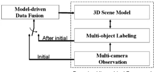
In our fusion-inference scheme, we design a data fusion stage to detect candidate targets and their 3-D locations first. After that, in the inference stage, target identification, image labeling, and inter-occlusion are analyzed under the proposed Bayesian hierarchical framework (BHF) based on the fused 3-D priors.
Fig. 1. System flow of the proposed system.
The inferred target labeling and correspondence results are fur-ther used to refine the 3-D target model, as illustrated in Fig. 1.
In the data fusion stage, a model-based approach is used to ef-ficiently fuse consistent 2-D foreground detection results from multiple camera views. Here, we formulated a posterior distri-bution, named target detection probability (TDP), as the mes-sage pool to indicate the probability of having a moving target at a certain ground location. With the TDP distribution, can-didate targets and their locations can be identified in a proba-bilistic manner. Moreover, with the use of 3-D target model, our fusion scheme may work well even with imperfect foreground extraction.
After data fusion, a set of candidate targets are detected, in-cluding both true targets and ghost targets. In our system, we use a few 3-D priors about the surveillance scenario, such as the probability distributions of target height and target loca-tion, to distinguish true targets from ghost targets. By prop-erly integrating these priors into the scene knowledge, we can greatly simplify the ghost suppression problem. Moreover, in the BHF framework, we introduce a labeling layer as the inter-face between scene knowledge and multicamera observations. This three-layer framework unifies the target labeling, target correspondence, and ghost suppression into a Bayesian infer-ence problem. Besides the intermediate role in the hierarchical framework, the labeling layer also provides a feedback route to refine the scene knowledge based on an Expectation-Maximiza-tion (EM) mechanism. In SecExpectation-Maximiza-tions III-A–III-D, we will explain in detail how we design the fusion stage and the inference stage.
III. INFORMATIONFUSION ANDSUMMARIZATION A. Foreground Detection on Single Camera
To fulfill the speed requirement of a real-time multicamera system, we only consider 2-D foreground detection results as the observation data. In our system, the intrinsic and extrinsic parameters of all cameras are well calibrated beforehand. For each camera, we build its reference background based on the Gaussian mixture model (GMM) approach [22]. The foreground image is determined by checking the frame difference between the current image and the reference background in a pixelwise manner. To remove shadows, the frame difference operation is performed over the chromatic domain. However, even though the GMM background subtraction method can deal with gradu-ally changing illumination through online background learning, it may still falsely reject some foreground pixels whose appear-ance happens to be similar to that of the reference background.
Fig. 2. (a) Visaul hull constructed from the foreground images of two camera views. (b) Voxel histogram based on visual hull in (a). (c) Visual hull constructed from fragmented foreground images. (d) Voxel histogram based on visual hull in (c). (e) Proposed pillar model in the 3-D space. (f) Estimated TDP distribution based on the foreground images in (e). [The red bar in (b), (d), and (f) represents the true target position.]
This fact may cause the detected foreground objects to be nei-ther perfectly silhouetted nor well connected.
B. Information Fusion
In the fusion step, we integrate the 2-D foreground detec-tion results from a set of camera views to offer global 3-D in-formation. To fuse information, most existing methods adopt a data-driven approach to back-project 2-D foreground regions into a 3-D visual hull, as plotted in blue in Fig. 2(a). By accumu-lating the number of voxels of the visual hull along the normal direction of the ground plane, we generate a histogram that indi-cates the likelihood of having a candidate target on the ground plane, as illustrated in Fig. 2(b). However, since the extracted 2-D foreground silhouettes are usually fragmental, the recon-structed visual hull could be very different from the original 3-D target and the deduced voxel histogram could be seriously bi-ased from the true location, as illustrated in Fig. 2(c) and (d).
To improve the accuracy in the estimation of target location, we adopt a model-driven approach to fuse 2-D information. In the proposed method, we define a Target Detection Proba-bility (TDP) distribution to estimate the probaProba-bility of having a moving target at a ground location. In Fig. 2(f), we show the estimated TDP distribution based on the incomplete foreground images in Fig. 2(e).
In our approach, the TDP distribution is formulated as a pos-terior distribution, as expressed below
(1) In (1), represents a location on the ground plane of the 3-D space. is the total number of cameras in the mul-ticamera system. denotes the foreground detection result of the th camera view. defines the set of camera parameters of all cameras. To simplify the formulation, we will ignore in the following deductions. Moreover, is used to define the prior information about the targets’ possible locations in the surveillance zone. If there is no specific knowledge about the probable locations of the moving targets, we can simply define
to be uniformly distributed over the ground plane of the surveillance zone.
To define , we use to represent the 2-D coordinate system of the th camera. If this camera has the image size of pixels, we define the image view of the th camera
to be the set of with and
. Based on the foreground detection result on the th camera view, we define as
if and foreground regions
if and background regions
if .
(2) In a multicamera system, some moving targets may only be monitored by a portion of the cameras, but not all the cam-eras. The introduction of in (2) is to indicate the possibility that some foreground target may exist in the scene even though that target does not appear in the field-of-view of the th cam-eras. With , we can represent the target detection probability (TDP) in a unified manner for these partially observed situa-tions. In our system, is set to be 0.08, which is estimated by calculating the ratio of partially observed situations to all situa-tions in our training datasets.
Moreover, given the location , we assume the foreground detection results are conditionally independent of each other. With this assumption, we rewrite (1) as
(3) To formulate , we model a moving person at the ground position as a rectangular pillar, as shown in Fig. 2(e). The height and width of the pillar are modeled as independent random variables. Their prior probability and are assumed to be Gaussian and are pretrained based on the data collected from the health center of our university. The means of and are 170 and 30 cm, respectively; while the standard deviations are 15 and 5 cm, respectively. Based on the pre-calibrated projection matrix of the th camera, a target at with height and width is projected onto the image plane of the th camera to obtain the projection region. Here, we define the projection image on the th camera view as
if projected regions if projected regions.
(4) Please note that the projected regions in (4) could be out of the image view of the th camera.
With and , the normalized overlapping area is de-fined as
(5) By taking into account the prior probabilities and , an estimate of is defined as
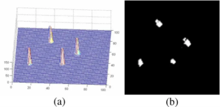
Fig. 3. (a) TDP of four moving targets in the surveillance zone. (b) Birds-eye view of (a).
In our approach, (6) is calculated numerically. Based on and , we define the integration range of target height and
width to be , where and denote the mean
and standard deviation of the corresponding probability den-sity function. Moreover, the integration ranges of and are uniformly divided into a 10 by 10 lattice. For a target at loca-tion and a pair of the lattice, we evaluate the product of its correlation value , its height probability , and its width probability . By summing up the product values over all pairs of the lattice, we can approximately
es-timate .
C. Information Summarization
To numerically calculate TDP, we calculate over a lattice on the ground plane. For each node of the lat-tice, its value indicates the probability of having an object at that location. The sample set , with , is then used to approximate the TDP
distribu-tion. In our experiments, we set and .
Based on the TDP distribution, we obtain some useful infor-mation about the 3-D scene, including the number of candidate targets, the most likely position of each candidate target, and the unique ID of each candidate target. Typically, the TDP dis-tribution contains several clusters, with each cluster indicating a moving target on the ground plane. Hence, the detection of mul-tiple moving targets can be treated as a clustering problem over the TDP distribution. In Fig. 3(a), we show an example of the TDP distribution, which is fused from the foreground detection results of four cameras.
To perform clustering over the TDP distribution, many ex-isting clustering methods can be used. In our system, we adopt the mean-shift clustering algorithm [21] due to the fact that this algorithm does not require the prior knowledge of the cluster number. Moreover, this algorithm usually produces more robust results if compared to some commonly used methods, such as K-means clustering and fuzzy c-means clustering.
In the mean-shift algorithm, by iteratively calculating the next position based on the following formula:
(7)
Fig. 4. Illustration of the ghost problem.
we can identify a few converging points. Those samples that converge to the same converging point are thought to belong to the same candidate target and are assigned the same ID. In (7),
is a parameter that controls the kernel size. In our system, is chosen to be 80 cm.
Assume we have identified candidate targets on the ground plane with the ID’s . If we denote the
sam-ples that belong to as with the
corresponding weights , we can
es-timate the position distribution function for . Here we model as a Gaussian distribution. The mean vector and covariance matrix of are estimated based on (8) and (9)
(8)
(9)
Under the assumption that is a Gaussian distribution, the location of is estimated to be , which is the minimum-variance unbiased estimate of the location.
D. Ghost Object
From time to time, ghost clusters may occur in the TDP distri-bution. Geometrically, the ghost effect happens when the projec-tion of a rectangular pillar at an incorrect locaprojec-tion accidentally matches the foreground detection results on the camera views. In Fig. 4, we present an illustration of the ghost problem when trying to reconstruct the 3-D scene based on two camera views. In this case, there are four reconstructed targets while only two of them are real targets. Please note that two extra ghost objects occur even based on perfect 2-D silhouettes.
IV. BAYESIANINFERENCE ANDGHOSTSUPPRESSION
After information summarization, we identify a few candi-date targets and their locations. For each candicandi-date, we have to decide whether its status is “true” or “ghost.” However, due to
Fig. 5. (a) An example of TDP distribution fused from four camera views. (b) The corresponding Bayesian hierarchical framework.
the inter-occlusion among candidate targets, the status of a can-didate target may actually affect the inference of others. Hence, in our approach, the statuses of all candidate targets are to be inferred simultaneously, rather than being decided individually. To determine the status of candidate targets, we consider not only foreground observations and geometric consistence but also some helpful prior knowledge about the targets. For example, as illustrated in Fig. 4, in the perspective back-projec-tion from the 2-D camera view to the 3-D space, the farther the candidate target is from the camera, the larger the reconstructed object would be. Since the 3-D size of a walking person actu-ally distributes over a specific range, the prior information of human size may offer useful information to exclude targets of unreasonable size.
A. System Modeling
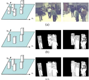
1) Bayesian Hierarchical Framework: In this paper, we pro-pose a three-layer Bayesian hierarchical framework (BHF) to simultaneously infer the status of candidate targets. In Fig. 5, without loss of generality, we consider an example of TDP dis-tribution fused from four camera views. The top layer of the BHF architecture is the scene layer that indicates the 3-D scene knowledge built at the fusion stage. Here, we treat the scene model as a knowledge pool collecting message from all cameras. The bottom layer is the observation layer , which
Fig. 6. (a) The scene layer in Fig. 5 and two of the four camera views. (b) The combinationfs ; s ; s ; s ; s g = f1; 0; 1; 1; 1g and the expected fore-ground images overlaid with the detected forefore-ground images. (c) The combi-nationf1; 1; 1; 1; 1g and the expected foreground images overlaid with the de-tected foreground images.
contains both the original images and the foreground detection results. Here, we define and as the original image and the foreground detection result of the th camera view. The value of is defined as in (2). Between the scene layer and the observation layer, a labeling layer is in-serted to deal with image labeling, target correspondence, and ghost removal. Here, we define as the labeling image of the th camera view.
2) Problem Formulation: In the “five candidate targets” case
in Fig. 6, the scene layer corresponds
to the status of five candidate targets, with each status node being either true “1” or ghost “0.” With five candidate targets, we have status combinations in total. For each combina-tion, we can generate the expected foreground occlusion pat-tern by approximating each “true” target as a rectangle pillar on the ground. By projecting the 3-D rectangle pillars onto each camera view, we form the expected foreground image. Ideally, the optimal status combination would lead to the best match between the expected foreground image and the detected fore-ground image. In Fig. 6, we show two status combinations based on the example in Fig. 5. In Fig. 6(a), the scene layer with five candidate targets, together with two of the four camera views, is shown for reference. In Fig. 6(b), we show the combination which assumes the second candidate is a ghost while the other four are true. By projecting the four 3-D pillars onto the camera views, we compare the ex-pected foreground image with the detected foreground image. In Fig. 6(c), we show another combination which as-sumes all candidates are true targets. By checking the projected foreground images, it appears that the latter combination is less likely than the former one.
Assume there are camera views and we have identified candidate targets based on the fused TDP distribution. In our system, target correspondence and image labeling are achieved
by assigning a suitable ID from the set to each pixel of the labeling images. Here, is the ID of the th target and represents the “background” object. The pro-cesses of labeling and ghost suppression are achieved by finding the optimal status combination that fits the foreground detection results. Hence, if we denote as the set of original images, as the set of foreground detection images, as the set of labeling images, and as a status combination, we unify the target labeling problem and the ghost suppression problem in a single MAP problem. In this problem, we seek the optimal status combination and the optimal target labeling that maximize the posteriori probability
(10) This equation is reformulated as below to decompose the infer-ence problem into the combination of a few cross-layer issues in the BHF architecture
(11)
In (11), we assume . That is, we
as-sume the probabilistic property of the observed data and are independent of the status combination once if the pixel labels are determined. This is because the classification la-bels, which are the target IDs, have already conveyed all the in-formation about the status . In (11), describes the relation between the labeling images and the observation data, describes the relation between the 3-D scene model and the 2-D labeling images, and describes the prior information about the 3-D scene model.
3) Formulation of : In our system, we formulate as
(12) In (12), is a normalization term.
denotes the “detection energy” that relates the th fore-ground detection image with the th labeling image. denotes the “adjacency energy” that relates the th original image with the th labeling image by checking the adjacent property within the neighborhood . Ideally, if the foreground objects are perfectly detected, we expect to be if is 0, and to be an element
of if is 1. Once a labeling violates
this expectation, a learnable constant , which will be deter-mined later, is added onto the detection energy to penalize this
inference. Hence, we define as
(13)
with being defined as
if
otherwise (14)
and being defined as if
otherwise. (15)
On the other hand, the local decisions of two adjacent labeling nodes are usually highly correlated, especially when their corresponding image pixels share similar color appearance. In our system, by taking the original image into consideration, we define the adjacency energy based on a Markov random field to provide a smoothness constraint between adjacent labeling nodes [24]. Here, we define
(16)
where
(17)
In (16), denotes the neighborhood around
, and is a learned penalty constant whose value is to be determined later. In (17), is defined as in (15). In our system, we design to be a discriminative function similar to a logistic sigmoid function
(18) In principle, works like a soft thresholding function, with and controlling its zero-crossing point and shape, respectively. outputs a positive value if is smaller than , and outputs a negative value otherwise. With this de-sign, is equal to zero when and
are the same. If and are
different, gives a larger penalty if the difference between
and is smaller than . Hence,
and tend to share the same label
when the difference between and
is small, and tend to have different labels otherwise. Moreover, the controlling parameters and are learned based on the color difference and labels of many manually collected adja-cent pixels in the training images. In our system, and
.
4) Formulation of : Given a status combination , we define a conditional probability to ex-press the likelihood of having a label at the pixel of the th labeling image. Here, with the status combination , we define a few rectangular pillars on the ground. The height and
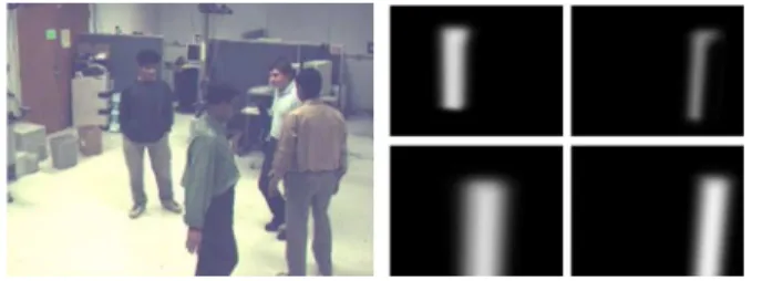
Fig. 7. Examples ofp(L (m; n) = T jS).
width of each pillar are sampled from and . The lo-cations of the pillars are sampled from , where indi-cates the th target. With the camera projection parameters, the expected foreground patterns for each target can be generated by projecting these rectangular pillars onto each camera view. Occasionally, more than two targets may project onto the same image region and cause occlusion. The inter-occluded patterns can be determined by checking the distance from the camera to the mean location of the targets. In Fig. 7, we demonstrate the
occlusion effect by plotting individually
for each of the four targets in Fig. 5(b).
Based on the definition of , we define
the log probability function as
(19)
and thus
(20)
On the other hand, the prior knowledge is also used in the determination of the optimal status combination. In our system, we assume the number of true targets at the current moment would be similar to that at the previous time instant. Hence, if we denote as the optimal status combination at the previous time instant and as a status combination at the current time instant , we define the prior probability of as
if
otherwise (21)
where and are two constants with . In (21), denotes the number of true targets in the status combina-tion . In detail, if we know the ratio between and , we can determine the value of such that the probability sum-mation equals to 1. For example, if we assume , the number of candidate targets at Time is 5, and the number of true targets in the previous optimal combination is 4, then
we have .
This leads to the setting that and .
B. Multitarget Labeling With Ghost Suppression
1) System Formulation: With the above deduction, the la-beling of targets and the suppression of ghost targets can be solved by finding the optimal labeling images and status
combination that maximize the following potential
func-tion :
(22)
In (22), we incorporate detection energy , adjacency energy , likelihood function , and prior prob-ability . As mentioned before, the detection energy represents the bottom-up constraint between the foreground detection images and the labeling im-ages. The likelihood function represents the expected labeling layout based on the status combination . The expected inter-occluded patterns among candidate targets are modeled in to influence the classification of local labeling nodes. By
introducing the adjacency energy ,
the proposed framework cannot only infer the labeling based on the fusion of scene knowledge and foreground detection results, but also refine the labeling results based on the original image data. Last, the prior probability includes the temporal prediction based on the previous decision.
2) Parameter Training: In (22), control the weights of detection energy and adjacency energy in the potential function . To determine , the method proposed by Yu et al. [23] is adopted. In detail, With the ground truth of our training data, we can manually label the optimal solution and the true target locations on the ground plane that maximize . For any other degraded solution , we have the relationship
that leads to an inequality constraint for and . After having collected an enough number of constraints for and , the op-timal parameter set can be found by finding the max-imal summation over the entire solution space of and subject to the collected constraints. That is
(23) where is the number of the degraded solutions used for training. The optimization problem in (23) is then solved by using a Linear Programming method.
3) Optimal Status Inference and Target Labeling: Due to the inter-occlusion among targets, the status inference of a candi-date target may depend on some other candicandi-date targets. When
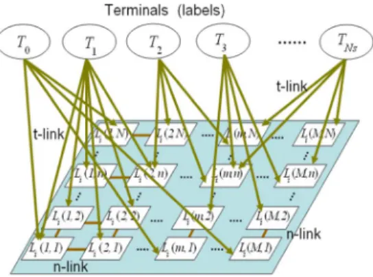
Fig. 8. The graph cut model for the optimal labeling.
we infer the status of a candidate target, we need to take into ac-count relevant candidate targets. A brute-force way to handle the inter-occlusion problem is to evaluate all possible status com-binations and then pick the optimal one as . However, this leads to exponentially growing computational complexity as the number of candidate targets increases. Fortunately, in general, there could be some kinds of separateness among candidate tar-gets. In our system, if the projection of a candidate target on a camera view does not overlap with the projection of other tar-gets, that candidate target is determined as a true target. By ex-cluding those targets with isolated projections, we only need to check the status combinations of the remaining targets. For ex-ample, in Fig. 5, the target corresponds to the left isolated target in the third camera view. That target is treated as a true target and we only need to generate status combinations for , and , instead of generating combinations for all five targets.
In addition, the status of a candidate target is usually affected by a few relevant candidate targets only. Those relevant proper-ties can be determined by projecting the 3-D candidate targets onto camera views and check the overlapping of the projections. Again, taking Fig. 5 as an example, is irrelevant to and . With this kind of relevance analysis, we can further decrease the total number of status hypotheses and avoid the exponential increase of computational complexity as the number of candi-date targets increases.
For each status hypothesis , we deduce the optimal that maximizes the potential function in (22). If
we treat , , and
as data terms and treat
as a smoothness term, actually follows a
canonical form that can be maximized based on many existing optimization algorithms [24]–[26]. Based on a recent study, the graph cuts method is proved to be more efficient in terms of running time as compared to loopy belief propagation, tree-reweighted, and iterated conditional mode algorithms [26]. Hence, in our system, the graph cuts algorithm [27]–[29] is
used for the maximization of .
In our system, the optimal image labeling under are achieved by assigning to each pixel a suitable ID from the set . Based on the graph cuts theory [27]–[29], we form a graph in Fig. 8 to represent our optimization problem. In this graph, a candidate target, say , can only
affect a portion of labeling nodes in the labeling image. Through the projection of the 3-D candidate target onto the th camera view, the relation is represented by a collection of
“t-links.” In our system, we combine ,
, and the prior as the data term to define the weight of each t-link. Moreover, the “n-links” in the graph represent the smoothness term, which is modeled
as . After forming this graph, our
optimization problem is equivalent to the cutting of the t-links and n-links with the minimal cost so that all terminals are separated and each labeling node only connects to one terminal through a t-link.
Moreover, in the graph cuts algorithm, the initial guess of is obtained by finding the labeling image of each camera view that maximizes the probability function in (19) under the status hypothesis . That is, we find the initial labeling image
of the th camera view such that
(24)
Among all status hypotheses, the status hypothesis that achieves the maximum posterior probability is picked as the optimal status combination . The optimal labeling of is then inferred as the optimal labeling .
In principle, the best configuration of labels depends on image data, foreground detection result, and scene model. In our exper-iments, even though plentiful false alarms and false rejections appear in the foreground detection results, these errors have little influence over the final inference results. Moreover, based on the proposed BHF, the inter-occlusion problem can be effectively analyzed, connected foreground regions can be well separated, and ghost targets can be correctly detected and removed.
4) 3-D Target Model Refinement: In our system, the 3-D model of each target is a pillar model with parameters height and width standing at a location on the ground plane. However, different targets may have different heights and widths. If personalized target models can be obtained, the per-formance of the inference framework can be boosted. However, in real situations, it would be impractical to obtain personalized 3-D model parameters in advance. In our system, we treat these model parameters as latent random variables and introduce an EM-based algorithm to iteratively refine the parameters.
The basic idea is to update the 3-D model parameters, and , in the Expectation step based on the labeling results derived from the optimization procedure in (22). In the Maximization step, by using (6) to consider the refined statistics of the 3-D model parameters in an expectation sense, the optimization pro-cedure in (22) is re-executed to boost the inference performance. This EM operation is repeated until the updated parameters con-verge or the maximal number of iterations is met.
Initially, the proposed EM algorithm adopts the pretrained probability distributions and to model the uncer-tainty of each target’s height and width. Since the BHF frame-work combines not only the 3-D scene priors and target priors but also the observed image data and the corresponding fore-ground detection result, the optimal target labeling reveals per-sonal properties of each detected target. Hence, based on the
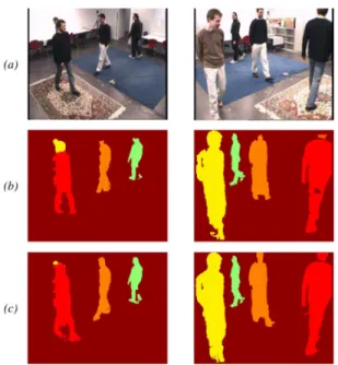
la-Fig. 9. (a) Two camera views. (b) Labeling results without target model refine-ment. (c) Labeling results with target model refinerefine-ment.
beling results, we update the probability distributions of and and establish personalized 3-D models gradually.
In Fig. 9, we show an example of the labeling results with and without target model refinement. Since the targets have quite different heights in this example, the labeling process based on a fixed target model generates incorrect labeling results around the heads, as shown in Fig. 9(b). With target model refinement, more accurate labeling results can be obtained, as shown in Fig. 9(c).
In detail, in the EM-based algorithm, the goal of the Expec-tation step is to refine the posterior probability of 3-D model parameters of each target given the multi-view labeling results. Here, we assume the model height and width are independent and can be refined separately. With Bayes rule, the refinement of the posterior probability is defined as
(25) where
if
otherwise.
In (25), denotes the labeling results of multiple image views at the th iteration. The notation represents the height or the width of the th target at the th iteration. Also, is a normalization constant, is the likelihood term to be defined later, and is the prior probability of . In our system, we treat as the prior information propagated from the previous iteration. For the first iteration,
is set to the pretrained probability.
To formulate the likelihood term , we project the pillar model at the ground position of the th target with height
and width onto multiple camera views to check the over-lapping regions with the labeling results. Ideally, if a more accu-rate model parameter is chosen, the projected region will better fit the labeling result. Hence, the likelihood is termed as
(26)
In (26), is the projected region of the th target onto the th camera view. is the probability of labeling the pixel at with the ID . is the total number of pixels within the projected region. Since different may generate different projected regions, we take the power for normalization. Moreover, we assume the statuses of different labeling pixels are independent and we evaluate only those pixels inside the projected region of the th target. In principle, the label ID tends to be . Hence, has a higher probability if equals to and has a lower probability if equals to . Occasionally, owing to occlusion, may equal to some other foreground target. In this case, we assign to be an intermediate value. That is, we define as
if if otherwise
(27)
where is a normalization constant to make the probability summation equal to 1. In (27), , , and are the weighting parameters with the value 5, , and 0, respectively, which sat-isfies the relation . If we rewrite (24) based on (25), we get a likelihood form as follows:
(28) where , is the number of -labeled pixels, is the number of -labeled pixels, and is the number of the other pixels inside the projected regions in all camera views. Basi-cally, (28) measures the degree of matching by accumulating the weighted sum of different labeling pixels inside the pro-jected regions with the weighting parameters . Once the likelihood term is determined, the refined probability distribution of the height and width of the th target height in the current iteration can be obtained based on (25). The refined
models and are inputted to the proposed
BHF for the next iteration of the optimal object labeling. In our experiments, it usually takes only 2 to 3 iterations to construct the refined target model.
5) Extension to Multitarget Tracking: In our system, we also extend the detection results to the tracking of target trajectory on the 3-D ground plane. By associating the temporal succes-sion, the object tracking problem is treated as a dynamic system problem with a motion model to predict the movement of each target. In this dynamic system problem, the major observations come from the estimated target locations on the ground plane. In principle, several Bayesian filtering techniques can be used to infer the solution. In our system, for the sake of computational
Fig. 10. One experiment result of our LAB sequence. (a) Four camera views. (b) Foreground detection images. (c) TDP distribution. (d) Voxel histogram based on visual-hull reconstruction. (e) Bird-eye view of target location. (f) La-beling and correspondence of targets in pseudocolor.
simplicity, we simply adopt the Kalman filtering approach to track each target.
V. RESULTS ANDDISCUSSION A. Experimental Datasets
To test our system over real video sequences, we set up four static cameras in our lab to capture test sequences. In our test sequences, the coverage is about 4.5 m by 4.5 m, with three to five targets moving within the zone. A set of snap shots with five persons inside the scene are shown in Fig. 10(a). On the other hand, we also tested our system over the video sequences provided by the M2Tracker project [11] and the sequence used in Fleuret’s papers [13]–[15]. Both video sequences are publicly available. The M2Tracker sequence was captured by 15 synchronized cameras over a 3.0 m by 3.0 m area, while Fleuret’s sequence was captured by four synchronized cameras in a 12.8 room.
For each sequence, four camera views are used to evaluate our system. If more camera views are used, the performance of our system can be further boosted. In Figs. 11(a) and 12(a), we show four snap shots in each of these two sequences.
For each sequence, the cameras have been geometrically cal-ibrated with respect to a world coordinate system. Except the M2Tracker sequence, each video sequence contains more than 300 frames. Especially, Fleuret’s video sequence contains as many as 3900 frames. For the evaluation of object ground loca-tion, we acquired the ground truth of M2Tracker sequence from Dr. Guan Li, the author of [20]. To establish the ground truth of Fleuret’s sequence, we manually identified the image posi-tions of human necks and used them as the corresponding points
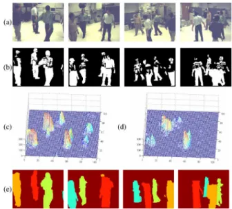
Fig. 11. One experiment result of the M2Tracker sequence. (a) Four camera views. (b) Foreground detection images. (c) TDP distribution. (d) Voxel his-togram based on visual-hull reconstruction. (e) Labeling and correspondence of targets in pseudocolor.
Fig. 12. One experiment result of the Fleuret’s sequence. (a) Four camera views. (b) Foreground detection images. (c) TDP distribution. (d) Voxel his-togram based on visual-hull reconstruction. (e) Labeling and correspondence of targets in pseudocolor.
among images. By backprojecting these corresponding points onto the 3-D space, object locations on the ground plane can be estimated. Here, we manually created a ground truth frame for every other 25 frames. To see the details of our experimental re-sults, please visit our website [31].
B. Foreground Detection and Information Fusion
For each video sequence, foreground objects are detected based on the popular GMM background subtraction algorithm [32]. Shadow removal [33] is also included to suppress false detection. In Figs. 10(b), 11(b), and 12(b), we show the detected foreground images, where plentiful false detections occur due to the appearance similarity between foreground objects and background. In Figs. 10(c) and (d) and 11(c) and (d), we compare the fusion results based on the proposed model-based
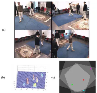
Fig. 13. (a) Four camera views. (b) TDP distribution. (c) Bird-eye view of target location.
method and the results based on the conventional data-driven method. It can be seen that the proposed model-based approach generates more reasonable fusion results.
C. Accuracy of Target Location
In our experiments, target locations on the ground plane were estimated and displayed in a bird-eye view, as shown in Fig. 10(e). To assess system performance, we calculate the de-viation of the estimated location from the ground truth location. We first compare the performance between the model-based fusion method and the conventional data-driven fusion method, by measuring the mean deviation in each frame for Fleuret’s video sequence. Numerically, the averaged mean deviations for the whole sequence are 0.087 and 0.073 m for the data-driven method and our model-based method, respectively. As a refer-ence, the foot length of an adult is around 0.25–0.30 m. Hrefer-ence, the 0.087 m deviation is thought to be quite close to the ground truth when tracking the location of a moving person.
To analyze the performance of target location when a target is not monitored by all cameras, we show an example of Fleuret’s sequence in Fig. 13(a), where the person wearing blue jeans can only be observed in the second and third camera views. The TDP distribution in Fig. 13(b) shows that this person corresponds to a small but still detectable cluster at the upper-right corner of the TDP distribution. Some other ghost objects also exist. With the BHF framework for ghost removal, ghost targets are removed and all four targets are correctly detected, as shown in Fig. 13(c). In Fig. 13(c), we use three different gray levels, from bright to dark, to indicate three different types of surveillance zones: four-camera zone, three-camera zone, and two-camera zone. For Fleuret’s sequence, 76% of the moving humans are monitored by four cameras, 21% by three cameras, and 3% by two cameras. Ideally, with the use of the 3-D target models and the assumption that targets stand on the ground plane, one camera view would be enough to roughly allocate the targets on the ground plane. However, the uncertainty caused by imper-fect foreground detection may dramatically degrade the
accu-TABLE I
ACCURACY OFTARGETLOCATION OFDIFFERENTSURVEILLANCEZONES FOR
FLEURET’SSEQUENCE
Fig. 14. Comparison of the mean deviation profiles over the M2Tracker se-quence.
racy of target localization. By using multiple cameras to cover the same surveillance, the accuracy can be improved. However, there is a tradeoff between the accuracy of location and the size of surveillance zone. When a zone is surveyed by more cameras, better localization accuracy is achieved but with the sacrifice of surveillance area. In Table I, we list the accuracy of the esti-mated target location within each kind of surveillance zone. As expected, the location accuracy goes down when the number of cameras decreases.
We also used the M2Tracker sequence as the benchmark to evaluate the accuracy of target location. For this M2Tracker se-quence, experimental results of a few other systems are avail-able. In Fig. 14, we compare the mean deviation profile of the M2Tracker sequence over four different systems: M2Tracker [11], Cost track [30], Li’s algorithm [20], and ours. Please note that only four camera views are used in our system, rather than the eight camera views used in the other three methods. D. Detection and Labeling With Ghost Removal
As shown in Figs. 10–12, the computed TDP distribution re-veals distinguishable clusters for candidate target identification and localization. The number and the location of the candidate targets can be decided by the mean-shift clustering algorithm. With the presence of ghost objects, the number of candidate tar-gets is typically larger than the true number. After the inference stage, the results of ghost suppression, labeling, and correspon-dence are presented in (f) or (e) of Figs. 10–12. These results demonstrated that the scene knowledge is very helpful in the labeling process even under severe inter-target occlusion. Be-sides, these ghost targets have been effectively removed by the proposed BHF framework.
TABLE II
FALSEPOSITIVERATE(FPR), FALSENEGATIVERATE(FNR)
Fig. 15. Multitarget tracking Results. (a) M2tracker sequence (four persons). (b) Lab sequence (five persons).
To quantitatively evaluate the detection and correspondence performance, false positive rate (FPR) and false negative rate (FNR) are used. In our system, the target detection and corre-spondence are defined as “correct” when the projected regions of the detected target in all camera views intersect the same in-dividual. Based on this definition, the calculated FPR and FNR of all tested datasets are listed in Table II. Here, the performance before and after ghost removal are provided for comparison. For both cases, the FNR is very low for all test sequences. On the other hand, the FPR is lowered after ghost removal. Moreover, if we compare with Fleuret’s experimental results in [15], where
and , our method achieves
and for the same sequence.
E. Target Tracking
Thought the main focus of this paper is multitarget labeling and target locating, instead of target tracking, the accurate target locations also make tracking of targets much easier. In our system, the multitarget detection results across successive frames are simply associated to establish temporal tracking of the targets based on Kalman filtering. In Fig. 15, we show the bird-eye view of our tracking results for the M2tracker sequence and the Lab sequence, with different colors indicating different targets.
Moreover, in Table III, we evaluate the tracking performance of our system based on the metrics used in Wu’s paper [34]. Those metrics include the following.
GT the number of “ground truth” trajectories;
MT the number of “mostly tracked” trajectories (more than 80% of the true trajectory is tracked);
ML the number of “mostly lost” trajectories (more than 80% of the trajectory is lost);
Fgmt the number of fragmented trajectories; FAT the number of false alarm trajectories; IDS the number of identity switches.
TABLE III
TRACKINGPERFORMANCESOVERFLEURET’S SEQUENCE. NGRNTC:NOGHOST
REMOVAL,NOTEMPORALCONSISTENCY. NGRWTC:NOGHOSTREMOVAL, WITHTEMPORALCONSISTENCY. WGRNTC: WITHGHOSTREMOVAL,
NOTEMPORALCONSISTENCY. WGRWTC: WITHGHOSTREMOVAL, WITHTEMPORALCONSISTENCY
TABLE IV
TRACKINGPERFORMANCESWITHBOTHGHOSTSUPPRESSION AND
TEMPORALCONSISTENCECHECKUNDERDIFFERENTNUMBERS OFCAMERASOVER THEM2TRACKERSEQUENCE
In the evaluation of our system, very few targets get lost in tracking and the falsely detected trajectories are mainly caused by ghost targets. Occasionally, identities may get incorrectly switched when two targets are very close to each other on the ground plane. As listed in Table III, with the proposed ghost re-moval scheme, the number of false trajectories (FAT) is reduced from 48 to 18. Similar improvement can be found for the eval-uations of Fgmt and IDS.
Besides, with ghost removal, the averaged duration of these falsely detected trajectories is also shortened. In our experi-ments, the duration of false trajectories is reduced from 7.2 frames per trajectory down to 2.3 frames per trajectory. As aforementioned, a few multicamera approaches have used the temporal consistency property for the suppression of fake tra-jectories [18], [19]. In their approaches, if a trajectory lasts only for a short period, that trajectory is thought to be a fake one. In our experiment, we have tested the application of temporal consistency by constraining the period of a trajectory to be longer than six frames; otherwise, that trajectory is removed. As listed in Table III, if the temporal consistency check is applied to the detection results without ghost removal, the FAT number is reduced from 48 to 37. When the ghost removal scheme is adopted, the FAT number is further reduced down to 2.
Moreover, the robustness of tracking with different numbers of cameras is also evaluated over the M2tracker sequence. The comparisons are shown in Table IV. As expected, we can obtain better performance when more camera views are used.
In summary, the tracking evaluation of our system has demonstrated reasonable performance even based on the simple Kalman filtering approach. Since most ghost targets have been removed after ghost removal and the lasting period of the remaining ghost targets is shortened, we can achieve target tracking in an easier and more efficient way.
F. System Complexity
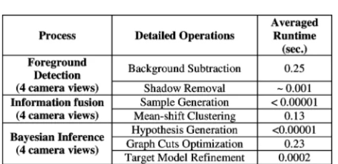
The whole system is implemented in a Visual C++ environ-ment on a PC with 3.0 GHz Core 2 Duo CPU. To evaluate the computational complexity of our system, we analyze the exe-cution time of our system based on the M2Tracker sequence. In Table V, we list the major processes of our system and the
TABLE V LIST OFCOMPUTATIONTIME
averaged runtime of each process at one time instant with four camera views. As shown in the table, the major computations are spent over background subtraction, mean-shift clustering, and graph-cut optimization. If excluding the background subtraction process, it takes about 3–6 s to perform the processes of posi-tioning, labeling, correspondence, 3-D target model refinement, and ghost suppression over four image shots with 320 240 res-olution. It takes longer time if there are more candidate targets in the scene. On the other hand, if we simplify the inference process to perform 3-D positioning and ghost suppression only, the whole computation time can be reduced down to around 0.2 s for every four image shots.
VI. CONCLUSION
In this paper, we proposed an efficient way to simultaneously detect, locate, and label targets across multiple cameras. In our approach, ghost effect is analyzed and suppressed. Moreover, individual 3-D target model is iteratively refined. In principle, our algorithm consists of two major steps: information fusion and Bayesian inference. The proposed model-based information fusion step collects consistent information from multiple cam-eras. Fused information is coupled with priors to establish scene knowledge. Scene knowledge is then treated as extra informa-tion to be used in labeling, correspondence, and ghost suppres-sion. In the Bayesian inference step, the whole process is mod-eled and resolved under the proposed BHF framework. Based on the BHF framework, inter-target occlusion, ghost suppres-sion, and determination of target number are effectively handled in a systematic manner. Moreover, an EM based mechanism is used to iteratively refine target models in order to further boost system performance. Experimental results have demonstrated that our system can systematically label objects and build ob-ject correspondence among multiple camera views even under severe occlusion. In addition, our system requires neither accu-rate foreground extraction nor color calibration among cameras.
ACKNOWLEDGMENT
The authors would like to thank all the editors and the anony-mous reviewers for their comments. They would like to thank Dr. G. Li for his helps in the experiments over the M2Tracker se-quence. They also would like to acknowledge Dr. A. Gupta and Dr. Fleuret for sharing sequences in Internet. They thank both Dr. Li and Dr. Gupta for offering helps on using their sequences.
REFERENCES
[1] H. Schneiderman and T. Kanade, “Object detection using the statistics of parts,” Int. J. Comput. Vision, vol. 56, no. 3, pp. 151–177, Feb. 2004. [2] P. Viola and M. Jones, “Robust real-time face detection,” Int. J.
Comput. Vision, vol. 57, no. 2, pp. 137–154, May 2004.
[3] T. Zhao and R. Nevatia, “Bayesian human segmentation in crowded situations,” in Proc. IEEE Int. Conf. Comput. Vision Pattern Recogn., 2003, vol. 2, pp. 459–466.
[4] T. Zhao and R. Nevatia, “Tracking multiple humans in complex sit-uations,” IEEE Trans. Pattern Anal. Mach. Intell., vol. 26, no. 9, pp. 1208–1221, Sep. 2004.
[5] T. Zhao and R. Nevatia, “Tracking multiple humans in crowded envi-ronment,” in Proc. Int. Conf. Comput. Vision Pattern Recogn., 2004, pp. 406–413.
[6] T. Zhao, R. Nevatia, and B. Wu, “Segmentation and tracking of mul-tiple humans in crowded environments,” IEEE Trans. Pattern Anal.
Mach. Intell., vol. 30, no. 7, pp. 1198–1211, Jul. 2008.
[7] S. Khan and M. Shah, “Consistent labeling of tracked objects in mul-tiple cameras with overlapping fields of view,” IEEE Trans. Pattern
Anal. Mach. Intell., vol. 25, pp. 1355–1360, Oct. 2003.
[8] W. Hu, M. Hu, T. Tan, J. Lou, and S. Maybank, “Principal axis-based correspondence between multiple cameras for people tracking,” IEEE
Trans. Pattern Anal. Mach. Intell., vol. 28, no. 4, pp. 663–671, 2006.
[9] J. Black and T. Ellis, “Multi camera image measurement and corre-spondence,” Measurement—J. Int. Meas. Confed., vol. 35, pp. 61–71, Jul. 2002.
[10] A. Mittal and L. Davis, “Unified multi-camera detection and tracking using region-matching,” in Proc. IEEE Workshop on Multi-Object
Tracking, Vancouver, BC, Canada, Jul. 2001, pp. 3–10.
[11] A. Mittal and L. Davis, “M2Tracker: A multi-view approach to seg-menting and tracking people in a cluttered scene,” Int. J. Comput.
Vi-sion, vol. 51, no. 3, pp. 189–203, Feb. 2003.
[12] A. Utsumi, H. Mori, J. Ohya, and M. Yachida, “Multiple-human tracking using multiple cameras,” in Proc. IEEE Int. Conf. Autom.
Face and Gesture Recogn., 1998, pp. 498–503.
[13] F. Fleuret, R. Lengagne, and P. Fua, “Fixed point probability field for complex occlusion handling,” in Proc. IEEE Int. Conf. Comput. Vision, 2005, pp. 694–700.
[14] J. Berclaz, F. Fleuret, and P. Fua, “Robust people tracking with global trajectory optimization,” in Proc. IEEE Int. Conf. Comput. Vision
Pat-tern Recogn., 2006, pp. 744–750.
[15] F. Fleuret, J. Berclaz, R. Lengagne, and P. Fua, “Multi-camera people tracking with a probabilistic occupancy map,” IEEE Trans. Pattern
Anal. Mach. Intell., vol. 30, no. 2, pp. 267–282, Feb. 2008.
[16] C.-C. Huang and S.-J. Wang, “A Monte Carlo based framework for multi-target detection and tracking over multi-camera surveil-lance system,” in Proc. Eur. Conf. Comput. Vision Workshop on
Multi-Camera and Multi-Modal Sensor Fusion Algorithms and Appli-cations, Oct. 12–18, 2008, pp. 1–12.
[17] C.-C. Huang and S.-J. Wang, “Moving targets labeling and correspon-dence over multi-camera surveillance system based on Markov net-work,” in Proc. IEEE Int. Conf. Multimedia and Expo, Jun.–Jul. 28–3, 2009, pp. 1258–1261.
[18] S. M. Khan and M. Shah, “Tracking multiple occluding people by lo-calizing on multiple scene planes,” IEEE Trans. Pattern Anal. Mach.
Intell., vol. 31, pp. 505–519, Mar. 2009.
[19] K. Otsuka and N. Mukawa, “Multiview occlusion analysis for tracking densely populated objects based on 2-D visual angles,” in Proc. IEEE
Int. Conf. Comput. Vision Pattern Recogn., 2004, pp. 90–97.
[20] L. Guan, J.-S. Franco, and M. Pollefeys, “Multi-Object shape esti-mation and tracking from silhouette cues,” in Proc. IEEE Int. Conf.
Comput. Vision Pattern Recogn., Anchorage, AK, Jun. 2008, pp. 1–8.
[21] B. Georgescu, I. Shimshoni, and P. Meer, “Mean shift based clustering in high dimensions: A texture classification example,” in Proc. IEEE
Int. Conf. Comput. Vision, 2003.
[22] P. KaewTraKulPong and R. Bowden, “An improved adaptive back-ground mixture model for real-time tracking with shadow detection,” in
Proc. Workshop on Advanced Video-Based Surveillance Systems, 2001,
pp. 1–5.
[23] Q. Yu, G. Medioni, and I. Cohen, “Multiple target tracking using spatio-temporal Markov Chain Monte Carlo data association,” in Proc. IEEE
Int. Conf. Comput. Vision Pattern Recogn., 2007, pp. 1–8.
[24] T. Boykov, O. Veksler, and R. Zabih, “Markov random fields with effi-cient approximations,” in Proc. IEEE Int. Conf. Comput. Vision Pattern
[25] P. F. Felzenszwalb and D. P. Huttenlocher, “Efficient belief propaga-tion for early vision,” Int. J. Comput. Vision, vol. 70, no. 1, Oct. 2006. [26] R. S. Szeliski, R. Zabih, D. Scharstein, O. Veksler, V. Kolmogorov, A. Agarwala, M. Tappen, and C. Rother, “A comparative study of en-ergy minimization methods for Markov random fields with smooth-ness-based priors,” IEEE Trans. Pattern Anal. Mach. Intell., vol. 30, no. 6, pp. 1068–1080, Jun. 2008.
[27] Y. Boykov, O. Veksler, and R. Zabih, “Efficient approximate energy minimization via graph cuts,” IEEE Trans. Pattern Anal. Mach. Intell., vol. 3, pp. 1222–1239, 2001.
[28] V. Kolmogorov and R. Zabih, “What energy functions can be mini-mized via graph cuts?,” IEEE Trans. Pattern Anal. Mach. Intell., vol. 26, pp. 147–159, Feb. 2004.
[29] Y. Boykov and V. Kolmogorov, “An experimental comparison of min-cut/max-flow algorithms for energy minimization in vision,”
IEEE Trans. Pattern Anal. Mach. Intell., vol. 26, no. 9, pp. 1124–1137,
Sep. 2004.
[30] A. Gupta, A. Mittal, and L. S. Davis, “COST: An approach for camera selection and multi-object inference ordering in dynamic scenes,” in
Proc. IEEE Int. Conf. Comput. Vision, 2007, pp. 1–8.
[31] C.-C. Huang, “Huang’s projects,” 2010. [Online]. Available: http://140. 113.238.220/~chingchun/projects.html
[32] C. Stauffer and W. E. L. Grimson, “Adaptive background mixture models for real-time tracking,” in Proc. IEEE Int. Conf. Comput.
Vision Pattern Recogn., 1999, vol. 2, pp. 246–252.
[33] T. Horparasert, D. Harwood, and L. A. Davis, “A statistical approach for real-time robust background subtraction and shadow detection,” in
Proc. IEEE Int. Conf. Comput. Vision, 1999, pp. 1–19.
[34] B. Wu and R. Nevatia, “Tracking of multiple, partially occluded hu-mans based on static body part detection,” in IEEE Int. Conf. Comput.
Vision Pattern Recogn., Jun. 17–22, 2006, pp. 951–958.
Ching-Chun Huang (M’09) received the B.S., M.S.,
and the Ph.D. degrees in electrical engineering from National Chiao Tung University, Hsinchu, Taiwan, in 2000, 2002, and 2010, respectively.
He is currently an Assistant Professor with the De-partment of Electrical Engineering, National Kaoh-siung University of Applied Sciences, Taiwan. His re-search interests are in image/video processing, com-puter vision, and computational photography.
Sheng-Jyh Wang (M’95) received the B.S. degree
in electronics engineering from National Chiao-Tung University (NCTU), Hsinchu, Taiwan, in 1984, and the M.S. and Ph.D. degrees in electrical engineering from Stanford University, Stanford, CA, in 1990 and 1995, respectively.
He is currently a Professor with the Department of Electronics Engineering, NCTU. His research inter-ests are in the areas of image processing, video pro-cessing, and image analysis.