266 IEEE TRANSACTIONS ON INDUSTRIAL ELECTRONICS, VOL. 40, NO. 2, APRIL 1993
A Fuzzy Scheduling Controller for a
ComputerDisk File Track-Following Servo
Jia-Yush Yen, Member, IEEE, Fu-Jeng Wang, and Yung-Yaw Chen, Member, IEEE
Abstract-In this paper, a fuzzy scheduling capability is su- perimposed on a computer disk drive track-following servocon- troller to adjust for the plant variation as the actuator is locked onto different tracks on the disk. The fuzzy algorithm is used to best represent the complex relationship among the controllers for various tracks. Models of a Zentek 3100 disk drive actuator as it locks on a number of different tracks are experimentally identified to be the reference points. The H , design technique is then employed to obtain a robust optimal controller for each reference point. The actual controller for the disk drive actuator is then calculated using fuzzy interpolation. It is shown that with the controller scheduling action, the closed-loop perfor- mance is improved for the actuator at every track position. Error can be kept at a lower level than in the case where only a single controller is used.
I. INTRODUCTION
NE of the most popular research topics being cur-
0
rently addressed by control engineers is the use of “fuzzy logic control” in high-performance systems. The fuzzy logic controller is based on the syntax of natural language which translates human thinking into machine codes. It is thus very suitable in applications where system characteristics or control actions are less easily given in mathematical expressions. The fuzzy controller is known to perform well in, for example, settling time and perfor- mance robustness against plant variations [SI, [ 111. Many successful applications have been reported [12], and new systems are seeking to use this technology. In this paper, a fuzzy tuning controller is developed for a computer disk drive track-following servo. The computer disk drive con- troller design has accumulated many years of experience. It is not desirable for the industry to abandon this success and start a new approach. The fuzzy scheduling capability is thus imposed on the existing controllers so that the structure of the traditional linear controller will be main-Manuscript received October 2, 1992; revised November 25, 1992 and December 8, 1992. This work was supported by the Opto-Electronics & Systems Lab, Industrial Technology Research Institute, Hsinchu, Tai- wan, R.O.C.
J.-Y. Yen is with the Department of Mechanical Engineering, Na- tional Taiwan University, Taipei, Taiwan, R.O.C.
F.-J. Wang was with the Department of Mechanical Engineering, National Taiwan University, Taipei, Taiwan, R.O.C. He is now with the R.O.C. Army.
Y.-Y. Chen is with the Department of Electrical Engineering, Na- tional Taiwan University, Taipei, Taiwan, R.O.C.
IEEE Log Number 9207166.
tained while plant variation due to various track positions can be compensated by parameter scheduling. Since the controllers for various tracks do not show any convenient correlation with their position, the fuzzy interpolation becomes the most adequate tool for this situation.
The computer disk drive (often called the hard disk drive, HDD) is the fastest and most reliable on-line mas- sive data storage device used by many computer manufac- turers [l]. Recently, both IBM and Futamoto Hitachi have announced a new experimental drive which records more than 1 Gb/in2 [13], [17]. This achievement has made the HDD the most promising memory device for future miniaturized palm-top or pocket computers. Many tech- nology innovations have contributed to the success of high-density disk drives. One of the key technologies has been the improvement of the servo technique. High-end disk drives commercially available today use disks which achieve a recording density of about 2000 tracks/in (79 tracks/”). This means that the servosystem has to be able to position the head to well within the 1 p m range and with a bandwidth usually up to several hundred hertz. This accuracy in design has been obtained through exten- sive engineering experience combined with the insight of modern control theories [31, [4], [61, [141, [16]. Over the years, the disk drive servosystem has moved from the simple PID controller used by the IBM 3330 to achieve 132 p m tracking accuracy in 1971 [5] to the advanced H, design which achieves 1 p m accuracy [15]. As recording density increases further (more than 20 000 tracks/in in the new experimental disk drives), the head positioning servo will have to position the head to within 0.1 p m accuracy (ten times the accuracy of today’s devices). Many new mechanical problems will start to emerge. The stic- tion of the actuator bearing caused by manufacturing tolerances will start to affect the achievable servo resolu- tion. The drag force and the bias force introduced by the flexible cable linking the moving part of the drive to the disk drive controller board will also cause a dramatic change in the system behavior. Traditional linear servos will no longer be satisfactory, and some tuning ability shall be necessary.
In this paper, the track-following servocontroller of a Zentek 3100 disk drive manufactured by the Zentek Com- pany, Taiwan, is modified. As mentioned in the previous paragraph, the design of the computer disk file servocon- troller is the result of many years of experience, and has brought about the evolution in design technology from the
YEN et al.: FUZZY SCHEDULING CONTROLLER FOR TRACK-FOLLOWING SERVO
~
267
simple PID controller used in 1971 to the H, optimization technique used in today’s disk drives. While the design challenges of the next stage of development are weighty, it does not mean that recent successes need be abandoned. Thus, instead of replacing the traditional linear controller with a totally new compensator, a controller scheduling capability is implemented so that the plant variations due to different tracks can be compensated. The mathematical model for the actuator on various tracks is experimentally identified. The H, design technique is then employed to obtain a robust optimal controller for the disk head actua- tor at each track. The actual controller for the disk drive actuator at various tracks is then calculated from all of these controllers using a fuzzy interpolation. The fuzzy interpretation is used here mainly for its convenience in representing the relationships between various con- trollers. The identified track models do not show any convenient correlation with the track position. A simple function for interpolating among the controllers cannot be obtained. The fuzzy interpolation is therefore the most adequate tool in this situation.
It is shown that, provided with an accurate plant model, the H, design procedure for optimal control is very straightforward. The simulation results for each track can be directly implemented. The Schur balanced truncation technique is applied to ensure a low-order controller. Without the controller scheduling capability, the quality of the control depends very much on the nominal track on which the design is based. Since the actuator plant changes with its position, without a careful selection of the nomi- nal track, the servosystem can become unstable when the actuator is locked on different positions (refer to the discussion in Section V). With the controller scheduling action, the servoloop remains stable for all track positions. Furthermore, error can be kept at a lower level than in the case where only a single controller is used.
The following sections of this paper will be arranged as follows. First, a brief description of the disk drive ser- vosystem and the design specifications will be presented. Section I11 will contain the plant identification procedures and identification results. The H, controller design and the controller reduction results will be presented in Sec- tion IV. The fuzzy tuning algorithm will then be intro- duced in Section V, followed by the simulation results in Section VI. The controller implementation and the exper- imental results will be presented in Section VII, followed by concluding remarks.
11. SYSTEM DESCRIPTION
In this section, a brief description of the disk drive system is presented. The disk drive used in this experi- ment is a Zentek 3100 hard disk drive manufactured by the Zentek Company, Taiwan. The disk drive holds up to
120 Mbytes of formatted data with an access time of 15
ms. A sketch of the disk drive system is shown in Fig. 1. Digital data are recorded as different magnetizations in concentric rings on the surfaces of several spinning disks. An actuator is used to drive the read/write head to access
Data heod Suspension
,
Actuator
&
Data disk Voice COilmOtor
Fig. 1. Schematics of the computer disk drive.
the data. In the Zentek 3100 disk drives, a rotary-type actuator is used. The data tracks are spaced 20 p m apart on the disk surface, and the servocontroller will have to maintain the head to within less than 1 p m from the data track center. The actuator is driven by a voice coil motor. The positioning information in this disk drive is written on a dedicated servosurface, and all of the heads are as- sumed to follow the servohead rigidly. For the servo design purpose, the signal entering the voice coil motor current amplifier is defined as the plant input, and the position error signal (PES) measured by the data channel demodulator for the servosurface is defined as the plant output. A linear system model is usually used to describe the system behavior.
The data heads in the magnetic disk drive usually have to fly at less than 0.5 p m above the data surface in order to pick up the small signals generated by the spinning disk. Any dust particle in the air can get clogged between the slider and the disk and destroy both the read/write head and the recorded data. Thus, the entire head disk assembly (HDA) has to be sealed in a particle-free envi- ronment. A flexible ribbon cable is thus necessary to bring the data signals out of the sealed HDA, although this cable introduces a bias force on the actuator. Further- more, since the disk is always spinning when in operation, the induced air flow around the slider and actuator also generates a drag force on the actuator. These bias forces vary from track to track on the disk. In addition, the actuator has to be aimed in different directions to access different data tracks, and there is no guarantee that the dynamic characteristics remain the same for the actuator pointing in different directions. Using a signal controller for all tracks is satisfactory in the present disk drives; however, it is clearly not going to be adequate in the future with an increased demand on the tracking accu- racy.
111. SYSTEM IDENTIFICATION
The actuator system model identification is performed for the actuators located on different tracks on the disk. Since there are 1000 tracks on the disk, it is not possible for the commonly used microprocessors in the low-end disk drives with 64 Kbytes of memory to implement one controller for every track. In this paper, the models for the actuator at five track positions from the inside to the outside of the disk are identified, and the corresponding controllers are designed.
The model identification is performed by curve fitting the frequency response of the actuator dynamics. An
268 JEEE TRANSACTIONS ON INDUSTRIAL ELECTRONICS, VOL. 40, NO. 2, APRIL 1993 HP3563A dynamic structural analyzer is used for measur-
ing the frequency response and for performing the curve fit. The signal into the voice coil motor is defined as the plant input, and the PES signal from the demodulator is defined as the plant output. The actuator is running under closed-loop control, while a sweep sine signal is added to the plant input to excite the plant dynamics. The closed- loop identification is necessary for the actuator system for it would be very close to unstable without proper compen- sation. It is also well known [9] that the persistent excita- tion condition can still be met under closed-loop control provided the disturbance signal is rich enough. A linear system is assumed so that the least square curve fit in the frequency domain can be conducted. The linear system assumption is valid for a head position within half track width from the track center. This procedure is performed with the actuator locked onto different tracks so that the models for various tracks are obtained.
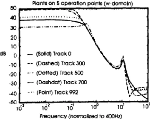
The frequency responses of the actuator at tracks 0, 300, 500, 700, and 992 are identified. Comparisons among the frequency responses of the resulting sixth-order curve fit models are shown in Fig. 2. It is noted that the first resonance peak of the actuator occurs at about 2 kHz. Higher order system models have been used, although little detail is reflected. Therefore, a sixth-order model is determined to be an adequate choice for the plant. As can be seen from the figure, a simple function describing the relationship between the track number and the low- frequency gain cannot be easily obtained, thus making the fuzzy description the most effective tool for this purpose. It is also observed that the major changes in the responses occur in the low-frequency region. The resonance fre- quency, however, remains almost unchanged, quite con- trary to expectation. Although a full controller interpola- tion is used in this work, in practice only a change in the low-frequency response is necessary.
Iv. H, DESIGN OF THE COMPUTER DISK DRIVE TRACK-FOLLOWING CONTROLLER
The
Ha
optimization technique is used for the con- troller design. The complementary sensitivity transfer function of the system is denoted by T ( s ) , and the sensi- tivity transfer function is denoted by S(s). The weighting function for the sensitivity transfer function is Wl(s), and the weighting function for the complementary sensitivity transfer function is W,(s).Since a TMS32OC30 board with 10 kHz sampling rate will be used for the controller implementation, the design is conducted in the w domain and the resulting controller is then transformed back into discrete-time domain for implementation. The control objective is to maintain the head centered within a 1 pm range from the track center. The desired closed-loop bandwidth is set at 400 Hz. A
- 40 dB/decade attenuation beyond the bandwidth is desired for robustness. In order to overcome the steady- state error, a very low-gain lead-type weighting function for the complementary sensitivity transfer function is used. In this paper, the weighting functions used are chosen to
Plants on 5 operation points (w-domain)
20 10 ’ dB 0 ,
-
(Saiid)TrackO -10 .--
(Dashed)TrackJW -20---
(Dotted) Track 500 -30 . -.- (Dashdot) Track 700 -40 . .... (Paint) Track 992 F r e q u e n c y (nonnoked to 400th)Fig, 2. Comparison of the model at different tracks.
be ( s / 3
+
1)2 (4.1) W1(s) = 0.01(s/0.02+
l ) ( s / l S+
1) (s+
1)* 5(s/20+
1)2 * W A S ) =The frequency is nomalized to 400 Hz. Wl(s) in (4.1) will ensure less than -40 dB gain in the low-frequency region and a bandwidth of over 400 Hz. The -40 dB low- frequency gain will ensure a less than 1% steady-state error. The weighting W,(s) will avoid the excitation of the 2 kHz resonance. Notice that the frequency is normalized to 400 Hz in these equations.
The
Ha
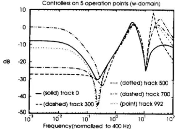
calculation for the sixth-order model resulted in a 12th-order compensator. It is clear that some model reduction is necessary as a practical consideration. The TMS320C30 used in this experiment is capable of han- dling complex calculations; however, most practical disk drives use slower microprocessors, which are also used for other tasks such as data channeling, etc. In this experi- ment, the Schur balanced truncation technique is used to obtain a sixth-order controller.The design procedure is carried out for all of the plant models identified in the previous section. Fig. 3 shows the frequency responses of the resulting compensators for each operation point. All of the controllers are basically composed of a very large lag compensator in the low- frequency region to provide enough loop gain, and basi- cally a lead-lag compensator in the high-frequency area, followed by a sharp high-frequency roll-off.
V. THE FUZZY SCHEDULING CONTROLLER DESIGN The tuning algorithm is designed based upon the con- cept that “the best controller for the system should be used whenever it is available.” Using the H, robust con- troller design, the nominal controller is stablizing for its neighboring tracks (usually one controller is used for all tracks). Since the optimal controller is not available for all
YEN et al.: FUZZY SCHEDULING CONTROLLER FOR TRACK-FOLLOWING SERVO 269
-a
dB
. -
. -
(solid) track 0 1 -.- (dashed) track 700. !?--(dashed) track 300 .'.. (Point) track 992
Controllers on 5 operatlon points (w-domain)
10 I , . . . . . I . . ,
..
. . . . , . . . . , . . q\
-50 + ' . . ' ' ' 'I....' ' ' " ' . . ' . " ' I , . U
Fig. 3. Frequency responses for the compensators at different tracks.
of the tracks, the actual controller will be obtained by interpolating from the nearest neighboring controllers. Notice that the term "best" is defined here in terms of the optimal condition, which includes the desired closed-loop bandwidth, the allowable steady-state error, and the opti- mal robustness. Thus, the theoretical optimal controller for the actuator at each track should be the one obtained by applying the H, procedure on the corresponding plant model. Ideally, the responses of sensitivity transfer func- tions or the complementary sensitivity transfer functions should be measured and compared to justify the resulting control. This can only be done numerically since, at pre- sent, it is not possible to experimentally measure the absolute reference track position. The PES signal ob- tained from the channel demodulator is the distance between the track and the head. In this paper, the rms errors for tracking a simulated track signal and the step responses will be compared in our simulation, and the actual rms values for the track-following error will be compared in the experiment.
The plant model at the five track positions is denoted by Po, P 3 0 0 , Psoo, P,,,, and P992, and the corresponding
H, controllers are denoted by CO, C3,,, C5,,, C7,,, and
C992. Numerical simulations for using various combina-
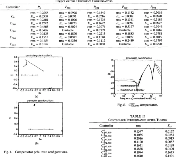
tions of the controllers acting on different tracks are performed. The resultant rms errors and the steady-state errors are listed in Table I. As can be seen from the table, using the appropriate controllers for its corresponding tracks always result in the lowest error; using a single controller for all tracks, on the other hand, can sometimes lead to instability, for example, C,,, on P3,,.
The motivation for this research is now clear. The controller scheduling ability for the computer disk file track-following controller is necessary if the tracking per- formance for the disk drive is to be further improved. As
mentioned in the beginning of this section, the basic concept for tuning is to use the most proper controller when available. When the best controller is not available, then the controller is obtained by the nearest neighboring controllers. This concept can be achieved by various means, the most direct of which is to use the entire transfer function for the interpolation. This method will
produce a resulting controller with an order as high as twice the original controller. In our approach, the con- trollers are represented with their poles and zeros whose values are calculated by the fuzzy scheduling logic. In order to carry out this concept, it is necessary to assume that the locations of the poles and zeros do not undergo abrupt change moving from the inside of the disk to the outside. Thus, the poles and zeros of the corresponding optimal controller will also move gradually as the actuator move tracks. Fig. 4(a) and (b) shows positions of the controller poles and zeros. (The conjugates are not shown in the figures.) It is observed that the poles and zeros can indeed be grouped into four different kinds, as indicated by the straight line connection in the figures.
The controller scheduling algorithm can now be de- signed. Let Tr represent the track number where the actuator is located, Tr E [O, 9921. Five fuzzy sets were defined for the input to the fuzzy logic, namely, about0, about300, about500, about700, and about992. Triangular- type fuzzy variables were used in this paper. The output of the fuzzy scheduling process is a sixth-order controller defined by
C ( z ) = K
( 2 - Z l ) ( Z - % ) ( Z - z a z - Z d ( Z - z5)(z - 2 6 )
( 2 - P l X Z - P 2 m - P 3 ) ( Z - P4)(Z - P a Z - P6) (5.1) where K , zl;**, z 6 , p l ; - - , p6 are the fuzzy variables whose values are calculated by the fuzzy rules.
Rule 1):
(Rl-1): If Tr is about 0, then p1 is 0.5327
+
j0.5638. (Rl-2): If Tr is about 300, then p1 is 0.4213+
j0.5760.(Rl-5): If Tr is about 992, then p 1 is 0.4807
+
j0.5825. Rule 2):(R2-1): If Tr is about 0, then p 2 is 0.5327 -jO.5638.
Rule 13):
(Rl3-1): If Tr is about 0, then K is 0.3004.
(R13-5): If Tr is about 992, then K is 0.4096. The values for the nominal gain constants K's, the nominal pole locations pi's, and the nominal zero loca- tions zi's are obtained by the H, optimization procedure. The weighted average method is then used for the de- fuzzification.
Five rules are involved for each output variable, even though no more than two rules will usually be fired. This will not affect the operation since the controller schedul- ing process can be carried out as a background process. Since one always knows the target track before the track accessing process begins, the tuning procedure can always
270 IEEE TRANSACTIONS ON INDUSTRIAL ELEGTXONICS, VOL. 40, NO. 2, APRIL 1993 TABLE I
EFFEC~ OF THE DIFFERENT COMPENSATORS
Controller PO '300 p500 rms = 0.2258 E,, = 0.0308 rms = 0.2401 G o o E,, = 0.2242 rms = 0.4605 c500 E,, = 0.0476 rms = 0.3135 c700 E,, = 0.1561 rms = 0.1454 C W 2 E,, = 0.0126 CO rms = 0.0998 E,, = 0.0091 rms = 0.1096 E,, = 0.0770 rms = 0.6024 Unstable rms = 0.1870 E,, = 0.0500 rms = 0.4336 Unstable rms = 0.1549 E,, = 0.0216 rms = 0.1734 E,, = 0.1672 rms = 0.3074 E,, = 0.0339 rms = 0.2213 E,, = 0.1140 rms = 0.1112 E,, = 0.0088 p700 rms = 0.1182 E,, = 0.0082 rms = 0.1341 E,, = 0.0697 rms = 0.5197 Unstable rms = 0.1883 E,, = 0.0427 rms = 0.2439 Unstable p992 rms = 0.3016 E,, = 0.0690 rms = 0.3189 E,, = 0.0697 rms = 0.5049 E,, = 0.1044 rms = 0.3781 E,, = 0.3015 rms = 0.1797 E,, = 0.0290
%1/
,\cotions , , , 0.2 I m o .%1/
,\cotions , , , 0.2 I m o .::::I
. , -0.6 -1 -0.8 -06-0.4 -0.2 0 0.2 0.4 0.6 0 8 1 Re (a)controller zero locations
1 0.8 3 Im 0.4 o.6
I
Controller combinotlon 1 0 1 ' I ' , ' , " " ' ' , ' 1 Frequency(nona1lzed to 4M) Hz)Fig. 5. C$&oo compensator.
TABLE I1
CONTROLLER PERFORMANCE AFIER TUNING
Controller rmS E,,
-0.2
"
U
- 1 -08-06-04-02 0 0 2 0 4 0 6 0 8 I Re
(b)
Fig. 4. Compensator pole-zero configurations.
0.1397 0.1085 0.2016 0.1100 0.1611 0.1838 0.1994 0.1610 0.1153 0.0132 0.0283 0.0913 0.0087 0.0188 0.0400 0.1615 0.1401 0.0423
start first, proceed during the accessing process, and con- c992, 700 0.2555 Unstable
vert to the target controller when the calculation is com-
fbtv I""
-
plete. Even if the conversion is not complete before reaching the target track, the original controller will re- main in action, preventing the tracking error from diverg- ing as long as the unstable situations denoted in Table I are avoided.
VI. SIMULATION RESULTS
This section contains the results from the simulation of the control action obtained by the combined controllers.
As a typical example, the solid line in Fig. 5 shows the frequency response of the controller for track number 500 obtained by the fuzzy algorithm using the data from track number 300 and track number 700. The same characteris- tics of the original controllers are still observed in the combined controller, indicating that the grouping of the controller poles and zeros is adequate. Numerical simula- tions are performed on various controller combinations. Table I1 shows the rms error and the steady error of some combinations of the combined controllers acting on vari- ous tracks. The symbol C~o,,,oo in Table I1 stands for the situation in which the controller for track number 0 and
the controller for track number 500 are used to obtain the controller for track number 300. Even though only five tracks are used for design points, it is observed that the errors are kept well under a more acceptable level, except for one extreme case.
VII. CONTROLLER IMPLEMENTATION
In this section, the experimental results from the fuzzy scheduling controller implementations will be presented. Applying the five operating design track data to the fuzzy rules presented in Section V, a linear controller for all of the tracks can be obtained from track 0 to track 992 on the disk. Letting C , denote the controller for track num-
ber n obtained by the fuzzy controller scheduling process,
the performance of the fuzzy scheduling controller will be presented. First, the controller C , is used to control the actuator at track n. Then the controller C , is used to control the actuator at neighboring tracks for comparison. A TMS320C30 digital signal processor board is used for the controller implementation. The board is equipped
YEN et al.: FUZZY SCHEDULING CONTROLLER FOR TRACK-FOLLOWING SERVO 21 1 with 4096 X 32 b of ROM and 2048 X 32 b of
RAM.
Using a 33.3 MHz clock with a 16 b A/D and D/A channel, the board is capable of sampling at 100 kHz; however, in this experiment, only a 10.43 kHz sampling rate and a very small amount of RAM space is used so that practical application of the method will be possible. The demodulated position error signal (PES) is fed into the controller as the error signal, and the calculated manipulated control input is sent to the voice coil drive to close the loop. The controller and the tuning process are all performed in real time. While the control action is being calculated in the foreground loop, the tuning pro- cess is performed in the microprocessor as well in the background process.
Again, only the typical situations will be presented. Fig. 6(a) and (b) shows the power spectrum density of the signals when C,,, is used on track number 500 and on track number 600, respectively. It can be observed that using
C,,,
on track number 500 has lower error signal intensity in the 10-200 Hz region. This indicates that the controller tuning has, in fact, improved the system perfor- mance. This tendency is further enhanced when the C,,,controller is used for track number 400 [Fig. 6(c)]. The effects of using different combined controllers on the same track are also compared. Due to space limitation, only the results of CO and Cloo acting on track number 100 are shown. Fig. 7(a) and (b) shows the PSD signal for the resulting PES signals. It can be seen that the smaller error is obtained when C,,, is used on track 100.
VIII. CONCLUSIONS
The application of fuzzy control has been gaining in- creasing attention in recent years; however, its application still finds emphasis on relatively complex or highly nonlin-
Fig. 6. (a) Power Spectrum IO Log Hz 1 Ok (b) IO Log Hr 10k (d
PSD of the PES signal C 5 0 0 / P s ~ o . (b) PSD of the C5,,a/P60,,. ( c ) PSD of the PES signal Csao/P400.
ear systems where models are difficult to obtain or where the control actions are hard to define. It is generally agreed that linear controllers have the advantages in the model is available.
Power Spectrum
25.0
12.5 lDiv frequency domain characteristics when an accurate plant
In this paper, fuzzy logic was used for a high-perfor- mance system. A fuzzy controller scheduling capability
dB rms v2 was implemented on a computer disk file actuator track-
following controller. The fuzzy scheduling controller was nal high-bandwidth loop obtained by the traditional linear
-75.0
implemented in the background process so that the origi- 10 Log Hz 1 Ok
(a) controller could be maintained. It was shown that as the
requirement for system accuracy and performance was raised, several mechanical problems appeared in the de- sign. These problems made the adequate actuator plant model vary from the inside tracks to the outside tracks on the disk. It was also shown that the variation of the model cannot be described by a simple function, making the fuzzy interpretation the most effective tool to describe the variation.
A Zentek 3100 disk drive was used for the research. Five operation points were chosen for the design. The simulation results showed that system stability is not guar- anteed when a single controller is used with very high
PES
(b)
Fig. 7. (a) PSD of the PES signal C,,/P1,,,,. (b) PSD of the PES C,oa/P100.
signal
212 IEEE TRANSACTIONS ON INDUSTRIAL ELECTRONICS, VOL. 40, NO. 2, APRIL 1993 system performance specified, and the performance can
be improved with a self-adjusting controller. In the fuzzy tuning algorithm, the controller was expressed in pole-zero form, and groups were formed for the poles and zeros of the controllers. Five rules were used for each fuzzy variable, and a total of 65 rules was used for the sixth-order controller with five design points. Simulation results showed that the resulting controller has an im- proved overall performance, while experimental results showed that real-time implementation of the algorithm is realistic.
Even though the proposed algorithm has been carried out under experimental conditions, rigorous proof of its stability and robustness still requires looking into. Owing to the flexibility of fuzzy logic, this method can be ex- tended to many applications such as airplane control, satellite control, etc., and where operating conditions are highly complicated. Further research and application of the method are expected.
ACKNOWLEDGMENT
Special thanks to the Research and Development Group at Zentek Company, Hsinchu, Taiwan, for supplying the disk drives and technical assistance.
[61
REFERENCES
C. H. Bajorek, “Trends in recording and control technologies and evolution of subsystem architectures for data storage,” in A d - vances in Information Storage Systems, B. Bhushan, Ed., ASME,
T. E. Bell, “Incredible shrinking computers,” IEEE Spectrum, pp.
37-41, May 1991.
R. D. Commander and J. R. Taylor, “Servo design for an eight-inch disk file,” IBM Disk Storage Technol., pp. 90-98, Feb. 1980.
G. F. Franklin, J. D. Powell, and M. L. Workman, Digital Control
of llynamic Systems, 2nd ed. Reading, MA: Addison-Wesley, 1990.
J. M. Harker, D. W. Brede, R. R. Pattison, G. R. Santana, and L. G. Taft, “A quarter century of disk file innovation,” IBM J. Res. Dev., vol. 25, pp. 667-689, Sept. 1981.
H. Hanselmann and A. Engelke, “LQG-control of a highly reso- nant disk drive head positioning actuator,” IEEE Trans. Ind. Elec- tron., vol. 35, pp. 100-104, Feb. 1988.
Intel 16-Bit Embedded Controllers, Intel Co. handbook, 1991.
Y. F. Li and C. C. Lau, “Development of fuzzy algorithms for servo systems,” IEEE Cont. Syst. Mag., pp. 65-72, Apr. 1989.
L. Ljung and T. Soderstrom, Theory and Practice of Recursive Identifcation. Cambridge, MA: M.I.T. Press, 1987.
J. H. Mayer, “3 1/2-in. Winchesters seek slots in high-perfor- mance disktop systems,” Comput. Design, pp. 144-150, Apr. 15,
1988.
X.-T. Peng, S.-M. Liu, T. Yamakawa, P. Wang, and X. Liu, “Self-regulating PID controllers and its applications to a tempera- ture controlling process,” in Fuzzy Computing, M. M. Gupta and T.
Yamakawa, Eds. Elsevier Science B. V. (North-Holland), 1988. M. Sugeno, “ A n introductory survey of fuzzy control,” Inform. Sci.,
R. Wood, “Magnetic megabits,” IEEE Spectrum, pp. 32-38, May
1990.
M. L. Workman, “Digital servo control system for a data recording disk file,” U. S. Patent 1 679 103, July 1987.
1991, pp. 1-14.
vol. 36, pp. 59-83, 1985.
[15] J. Y. Yen and C. S. Chang, “HE-controller for head positioning in a small computer disk file,” submitted to J. Dynamic Syst., Meas., Contr., 1992.
[16] J. Y. Yen, K. Hallamasek, and R. Horowitz, “Track-following controller design for a compound disk drive actuator,” ASME Trans. Dynamic Syst., Meas., Contr., vol. 112, pp. 391-402, Sept.
1991.
G. Zorpette, “Fujitsu predicts optical-density magnetic disk,” The Institute (IEEE), p. 6, Nov./Dec. 1991.
[17]
Jia-Yush Yen (M’89) was born in Taipei, Tai- wan, R.O.C., in 1958. He received the B.S. de- gree from National Tsing-Hwa University, Hsinchu, Taiwan, in 1980, the M.S. degree from the University of Minnesota, Minneapolis, in 1983, and the Ph.D. degree from the University of California, Berkeley, in 1989, all in mechani- cal engineering.
During his study at Berkeley, he received an IBM Graduate Fellowship in 1984-1985. Since 1989 he has been with National Taiwan Univer- sity, Taipei, Taiwan, where he is currently an Associate Professor of Mechanical Engineering. His research interests are in the areas of modeling and control of electromechanical systems, especially in preci- sion control of computer peripherals, precision measurement systems, and micromechanical systems.
Dr. Yen currently serves as the Treasurer of the Control Systems Chapter of the IEEE Taipei Section. He is also a member of the ASME.
Fu-Jeng Wang received the B.S. and M.S. de- grees in mechanical engineering from National Taiwan University, Taipei, Taiwan, R.O.C., in 1990 and 1992, respectively.
He is currently serving as a Second Lieu- tenant in the R.O.C. Army. His research inter- ests include H, control, fuzzy systems, and fre-
quency shaping.
Yung-Yaw Chen (S’86-M’89) was born in Taipei, Taiwan, on August 8, 1959. He received the B.S. degree in electrical engineering from National Taiwan University and the Ph.D. degree in elec- trical engineering and computer sciences from the University of California, Berkeley, in 1981 and 1989, respectively.
During his studies at Berkeley from 1984 to 1989, he was a Graduate Research Assistant in the Electronics Research Laboratory, Depart- ment of Electrical Engineering and Computer Sciences, working with Prof. L. A. Zadeh on topics related to fuzzy logic control systems. He received the Wilson and Albert M. Flagg Scholar- ship in 1984-1985. Since August 1989 he has been an Associate Profes- sor at the National Taiwan University in the Department of Electrical Engineering. His current research interests are in fuzzy logic control, neural control, and disk-head servocontrol.
Dr. Chen currently serves as the Secretary of the Control Systems Chapter of the IEEE Taipei Section, and is a member of the IEEE Control Systems Society, Computer Society, Neural Networks Society, and Systems, Man, and Cybernetics Society.