鋼骨托梁抗彎接頭含梯度漸擴式梁翼板之耐震行為
151
0
0
全文
(2) 誌. 謝. 在交大六年攻讀碩士與博士學位的求學生涯,是我人生中最寶貴的黃金年 代;追隨恩師 陳誠直教授的研究生涯,亦是我人生中最難得的學習歷程。感謝 恩師多年來的指導與提攜,讓學生能以嚴謹的態度面對求學與為人處世上的種種 難題,受益匪淺,師恩浩大無邊,弟子銘記在心間。於論文口試期間,承蒙國立 台灣大學土木系 蔡克銓教授、鐘立來教授、國立中興大學土木系 呂東苗教授與 本校 劉俊秀教授、周中哲教授對於本論文提供諸多寶貴的意見與指教,使得本 論文更臻完備,在此致上最誠摯之感謝。 特別感謝財團法人中興工程科技研究發展基金會提供獎學金,使我能無後 顧之憂的順利完成學業,特此誌謝;並蒙春源鋼鐵 郭金宇廠長、林祺華組長及 鴻舜機械 周仁財先生對於試體製作的配合與協助,在此深表謝忱。 本論文得以順利付梓,不諱言需感謝歷年來同門的師兄弟們,南交、澤許、 新梓、源興、潔祥、崇豪、文賢、智民、仁甫、文銘及建霖,於研究期間不分晝 夜的鼎力協助,在此一併誌謝。此外,在這六年的研究生涯中認識許多知心的學 弟妹,承載了滿滿的歡樂回憶,在此誠心的祝福大家,願你們前途無量。 最後,僅將本論文獻給我最摯愛的父母、家人及親戚們,感謝你們一直以 來的支持與體諒,在精神上給予許多關懷與鼓勵,願與你們一起分享我獲得博士 學位的喜悅與驕傲。. 群洲 九十五年十月.
(3) Seismic Performance of Steel Column-Tree Moment Connections with Tapered Beam Flanges. Student: Chun-Chou Lin. Adviser: Dr. Cheng-Chih Chen. Department of Civil Engineering National Chiao Tung University. ABSTRACT With a prospective advantage of better quality control of the shop welding, steel column-tree constructions are widely used in design practice of Taiwan and Japan nowadays. These connections used in the column-tree system are fabricated in the shop by welding short pieces of stub beams to the column. However, brittle fracturing of the column-tree connections was observed during the 1995 Kobe earthquake. The purpose of this study is to develop a new scheme of moment connections for steel column-tree moment-resisting frames. This connection improvement is intended to enhance the ductility of the connection by tapering portions of beam flanges following the seismic moment gradient. A series of the finite element parametric study was conducted to investigate the effect of the taper flange geometry on the connection performance. Numerical analyses revealed that significant yielding spread around the tapered region of the beam and took place away from the column face. Full-scale subassemblage specimens, consisting of a typical pre-Kobe connection and six tapered flange connections, were designed and tested to clarify their seismic performance. Experimental observations. i.
(4) demonstrated that the pre-Kobe specimen failed caused by a brittle fracture of the beam flange originated from the toe of the weld access hole, whereas the specimens with the tapered flange connection sustained a sufficient 5% rad story drift angle and resulted in stable energy dissipation. A design procedure of the tapered flange connection, accordingly, is proposed based on the results of the finite element analyses and full-scale connection tests. In addition, pushover analysis of frames with tapered flange connections was carried out. The performance of the tapered flange frames was compared to that of the moment-resisting frames with unreinforced connections. The results of the structural analyses demonstrated that frames with tapered flange connections have stable inelastic performance and satisfied ductility.. Key words:. column-tree, special moment frame, moment connection, pushover analysis, tapered beam flange.. ii.
(5) 鋼骨托梁抗彎接頭含梯度漸擴式 梁翼板之耐震行為 研究生:林群洲. 指導教授:陳誠直 博士. 國立交通大學土木工程學系 摘. 要. 鋼骨托梁式建築由於擁有較佳工廠銲接品質的優勢,因此普遍的被台灣與日 本的工程界採用。然而,於 1995 阪神地震中觀察到此型式之梁柱接頭發生非預 期的脆性破壞。本研究之目的為發展新型式之托梁抗彎接頭,改良方式為逐漸擴 大一部分之梁翼板使梁之彎矩容量符合耐震彎矩梯度,藉由大範圍之降伏區域提 高梁柱接頭的韌性行為。 一系列有限元素參數研究用以探討各設計參數對於梯度擴翼板幾何形狀之 影響。數值分析結果顯示,梯度擴翼式接頭可於梁梯度漸擴段展現廣泛的塑性降 伏範圍,並將塑性鉸機制移離梁柱交接處。實尺寸梁柱接頭試驗,包括試驗一組 傳統托梁式接頭與六組梯度擴翼式接頭,以驗證其耐震性能。試驗結果顯示,傳 統托梁式試體於扇形開孔根部之撕裂導致梁翼板之脆性斷裂;而梯度擴翼式試體 能發揮層間變位角 5% 弧度之行為,並提供穩定的消能效果。根據參數研究與實 尺寸梁柱接頭試驗之結果,提出梯度擴翼式梁柱接頭之設計流程。此外,本研究 利用非線性的構架側推分析,探討應用此梯度擴翼式接頭之抗彎構架的耐震特 性,並與採用傳統未補強式接頭之抗彎構架比較。構架分析結果顯示,採用梯度 擴翼式接頭之抗彎構架,具有穩定的非彈性行為及滿意的韌性能力。. 關鍵字:托梁、特殊抗彎構架、抗彎接頭、側推分析、梯度梁翼板. iii.
(6) List of Contents Abstract .......................................................................................................................... i List of Contents............................................................................................................ iv List of Tables................................................................................................................ vi List of Figures ............................................................................................................. vii Chapter 1. Introduction...............................................................................................1 1.1 Background ...............................................................................................1 1.2 Objectives of Research .............................................................................2 1.3 Scope and Approach of Research .............................................................2 1.4 Organization of Dissertation .....................................................................3 Chapter 2. Seismic Performance of Special Moment Frames ....................................5 2.1 General......................................................................................................5 2.2 Review of Previous Work .........................................................................5 2.2.1 Unreinforced moment connections with built-up box columns.......5 2.2.2 Welded reinforced moment connections..........................................7 2.2.3 Reduced beam section moment connections ...................................9 2.2.4 Improvements in connection details ..............................................10 2.3 Proposed Column-Tree Structural Systems with Tapered Flange Connections.............................................................................................11 2.3.1 Design concept...............................................................................13 2.3.2 Design parameters..........................................................................13 Chapter 3. Parametric Study .....................................................................................15 3.1 General....................................................................................................15 3.2 Analytical Model Description.................................................................15 3.2.1 Finite element modeling ................................................................15 3.2.2 Performance indicators ..................................................................17 3.2.3 Material properties .........................................................................18 3.3 Parametric Study of Tapered Flange Connection....................................18 3.3.1 Effect of tapered flange on connection behavior ...........................19 3.3.2 Effects of parameter β j and length of tapered zone Ltap ...........19 3.3.3. Effect of main reinforced part Lw1 ................................................20 3.3.4 Effect of tapered flange extension Lext .........................................21 3.3.5 Plastification of tapered flange connection....................................21 Chapter 4. Full-Scale Connection Tests....................................................................22 4.1 General....................................................................................................22 4.2 Design of Test Specimens .......................................................................22 4.3 Test Setup and Procedure........................................................................24 4.4 Observed Behavior of Test Specimens ...................................................25 4.4.1 Specimen PK..................................................................................25 4.4.2 Specimens of Series W ..................................................................25 4.4.3 Specimens of Series B ...................................................................27 4.5 Test Results and Discussion....................................................................27 4.5.1 Hysteretic response and failure modes ..........................................27 4.5.2 Connection moment capacity and envelope response ...................30 4.5.3 Energy dissipation..........................................................................30 Chapter 5. Evaluation of Analytical and Experimental Response............................32 5.1 General....................................................................................................32 iv.
(7) 5.2. Evaluation of tapered flange connection subassembly ...........................32 5.2.1 Global response..............................................................................32 5.2.2 Local response ...............................................................................33 5.3 Stress and strain distribution in connection ............................................34 5.3.1 Distributions of von Mises stress and equivalent plastic strain .....34 5.3.2 Force transfer in beam ...................................................................35 5.3.3 Strain response around connection ................................................38 Chapter 6. Design Recommendation ........................................................................40 6.1 General....................................................................................................40 6.2 Design Procedure ....................................................................................40 Chapter 7. Inelastic Structural Analysis for SMFs with Tapered Flange Connections.............................................................................................44 7.1 General....................................................................................................44 7.2 Design of Prototype Buildings................................................................44 7.2.1 Prototype building configuration ...................................................44 7.2.2 Elastic analysis of prototype buildings ..........................................45 7.3 Nonlinear Static Pushover Analysis........................................................50 7.3.1 Frame modeling and validation .....................................................50 7.3.2 Evaluation methodology ................................................................52 7.3.3 Discussion of analytical results......................................................53 Chapter 8. Summary and Conclusions .....................................................................57 8.1 Summary .................................................................................................57 8.2 Conclusions.............................................................................................58 References .................................................................................................................62 Appendix A Design Example ....................................................................................134 Appendix B Design Base Shear for Building............................................................136. v.
(8) List of Tables Table 3.1 Table 4.1 Table 4.2 Table 4.3 Table 5.1 Table 7.1 Table 7.2 Table 7.3 Table 7.4 Table 7.5 Table 7.6. Parameters used in finite element analysis .............................................65 Material properties of test specimens .....................................................66 Details of test specimens.........................................................................66 Overview of test results ..........................................................................67 Percentage of beam shear force for specimen W1-L03 ..........................67 Dead loads for studied buildings.............................................................68 Live loads for studied buildings..............................................................68 Distribution of design seismic forces for studied frames........................69 Tapered flanges used in studied frames ..................................................69 Confidence levels for different confidence parameters λ .....................70 Confidence level evaluation for studied frames......................................71. vi.
(9) List of Figures Figure 1.1 Figure 2. 1 Figure 2.2 Figure 2.3 Figure 2.4 Figure 2.5 Figure 2.6 Figure 2.7 Figure 2.8 Figure 2.9 Figure 2.10 Figure 2.11 Figure 2.12 Figure 3.1 Figure 3.2 Figure 3.3 Figure 3.4 Figure 3.5. Figure 3.6. Figure 3.7 Figure 3.8. Figure 3.9 Figure 3.10 Figure 4.1 Figure 4.2 Figure 4.3 Figure 4.4 Figure 4.5. Connection details of web-bolted flange-welded pre-Northridge moment connection. ..............................................................................................72 Connection details between H-shaped beam and welded built-up box column..............................................................................................73 A schema of SESNET electroslag welding.............................................73 Examples of reinforced moment connections.........................................74 Reinforced moment connection with wing plates. (陳嘉有 1995) ........75 Different RBS configurations .................................................................75 Weld access hole configurations: (a) a quarter-circular shape; (b) a modified shape recommended by FEMA-350. ..............................76 Steel column-tree moment frame............................................................76 Typical pre-Kobe column-tree connections: (a) Through-diaphragm connection; (b) Interior-diaphragm connection. .....................................77 Widened flange connection configuration. (Chen et al. 2006) ...............78 Normalized moment versus total plastic rotation curves for specimens W10-L2 and W08-L1. (Chen et al. 2006)...............................................78 Geometry of tapered flange connection..................................................79 Comparison with seismic moment demand and flexure capacity: (a) for tapered flange connections; (b) for widened flange connections............79 Geometry of 3-D structural solid element SOLID45 (ANSYS 2002)....80 Boundary conditions and meshes of finite element model. ....................80 Details of weld access hole. ....................................................................81 Critical sections of pre-Kobe connection: (a) at CJP groove weld; (b) at root of WAH. .................................................................................82 Distributions of normalized principal stresses and PEEQ indices along beam flange width at CJP weld and root of WAH: (a) normalized principal stress at 0.5% rad story drift angle; (b) PEEQ indices at 4% rad story drift angle........................................................................................................83 Effect of different values of parameter β j and length of tapered part Ltap on PEEQ indices at 4% rad story drift angle: (a) at borders of CJP weld; (b) at root of WAH........................................................................................84 Effect of length of main tapered flange reinforced part Lw1 on PEEQ indices at 4% rad story drift angle. .........................................................85 Effect of length of tapered flange extension Lext on PEEQ indices along root of WAH between column-tree and link beam at 4% rad story drift angle........................................................................................................85 Longitudinal plastic strain contours for different configuration of connections during 4% rad story drift angle. ..........................................86 Contour plots of plastic equivalent strain for different configurations of connections at 4% rad story drift angle...................................................86 Connection details of specimen PK. .......................................................87 Connection details of specimen W1-L05, W1-L03, W2-L03, and W3-L03. ..................................................................................................88 Connection details of specimen B1-L03 and B2-L03.............................89 Overall view of test setup .......................................................................90 Loading history .......................................................................................91 vii.
(10) Figure 4.6 Figure 4.7 Figure 4.8. The definition of story drift angle for test assembly (FEMA-350 2000)91 Failure mode of typical pre-Kobe specimen PK.....................................92 Fracture of beam flange groove weld of specimen W3-L03 at 4% rad story drift angle. ...............................................................................................92 Figure 4.9 Plastic hinge formation followed by local buckling at 5% rad story drift angle: (a) specimen W1-L05; (b) specimen W1-L03. ............................93 Figure 4.10 Slight cracking at root of weld access hole of specimen B1-L03 at 4% rad story drift angle. ......................................................................................94 Figure 4.11 Local buckling of beam flanges and beam web at 5% rad story drift angle: (a) specimen B1-L03; (b) specimen B2-L03. .........................................95 Figure 4.12 Hysteresis response of specimen PK: (a) normalized moment at column face versus story drift angle; (b) normalized moment at column face versus total plastic rotation. ....................................................................96 Figure 4.13 Normalized moment versus rotation responses of column-tree tapered flange connection specimens: (a) in terms of story drift angle; (b) in terms of total plastic rotation. ...........................................................................97 Figure 4.14 Normalized moment versus rotation responses of web-bolted flange-welded tapered flange connection specimens: (a) in terms of story drift angle; (b) in terms of total plastic rotation......................................98 Figure 4.15 Ratios of maximum test moment to calculated moment capacity of the specimens PK, W1-L03, and W2-L03 along the length of the beam. ....99 Figure 4.16 Envelope relationships of normalized moment versus story drift angle: (a) specimens with column-tree connection; (b) specimens with web-bolted flange-welded connection. ....................................................................100 Figure 4.17 Comparison of test specimen energy dissipation..................................101 Figure 5.1 Comparison of experimental and analytical beam tip load versus beam tip displacement response of specimen W1-L03. ......................................101 Figure 5.2 Position of strain gauges: (a) specimen PK; (b) tapered flange specimens..............................................................................................102 Figure 5.3 Verification of longitudinal strain distributions at line F40 for specimen W1-L03. ................................................................................................103 Figure 5.4 Verification of longitudinal strain distributions around tapered zone of beam flange for specimen W1-L03.......................................................104 Figure 5.5 Von Mises stress contours, equivalent plastic strain contours, and yielding behavior during testing of specimen W1-L03: (a) at 1% rad story drift angle; (b) at 2% rad story drift angle. ...................................................105 Figure 5.5 (continued) Von Mises stress contours, equivalent plastic strain contours, and yielding behavior during testing of specimen W1-L03: (c) at 3% rad story drift angle; (d) at 4% rad story drift angle......................................106 Figure 5.6 Normalized shear stress distributions along beam web depth at 0.5% rad story drift angle. ....................................................................................107 Figure 5.7 Normalized shear stress distributions along beam flange width at 0.5% rad story drift angle. ....................................................................................108 Figure 5.8 Normalized longitudinal stress distributions along beam web depth at 0.5% rad story drift angle......................................................................109 Figure 5.9 Normalized longitudinal stress distributions along beam flange width at 0.5% rad story drift angle...................................................................... 110 Figure 5.10 Normalized shear stress distributions along beam web depth at 4% rad story drift angle. .................................................................................... 111 viii.
(11) Figure 5.11 Normalized shear stress distributions along beam flange width at 4% rad story drift angle. .................................................................................... 112 Figure 5.12 Normalized longitudinal stress distributions along beam web depth at 4% rad story drift angle............................................................................... 113 Figure 5.13 Normalized longitudinal stress distributions along beam flange width at 4% rad story drift angle......................................................................... 114 Figure 5.14 Distributions of normalized longitudinal strains along beam flange width at line F-40 between specimens PK and W10-L03............................... 115 Figure 5.15 Distributions of normalized longitudinal strains across tapered zone of beam flange for column-tree specimens: (a) specimen W1-L05; (b) specimen W1-L03; (c) specimen W2-L03; (d) specimen W3-L03. ..... 116 Figure 5.16 Distributions of normalized longitudinal strains across tapered zone of beam flange for web-bolted flange-welded specimens: (a) specimen B1-L03; (b) specimen B2-L03.............................................................. 117 Figure 6.1 Moment gradient of tapered flange connection .................................... 118 Figure 7.1 Floor plane view of prototype building. ............................................... 119 Figure 7.2 Design details of prototype buildings: (a) five-story frame; (b) fifteen-story frame...........................................................................120 Figure 7.3 Analytical models for prototype buildings: (a) model UR-5F; (b) model TF-5F.....................................................................................................121 Figure 7.4 Analytical models for connection subassemblage: (a) model UR-C; (b) model TF-C. ..........................................................................................122 Figure 7.5 Properties of pushover hinge for model UR-C used in SAP2000. .......123 Figure 7.6 Properties of pushover hinge for model TF-C used in SAP2000. ........124 Figure 7.7 Verification of experimentally cyclic and numerically monotonic responses: (a) model UR-C; (b) model TF-C. ......................................125 Figure 7.8 Pushover curves of normalized base shear versus roof drift for five-story frames....................................................................................................125 Figure 7.9 Distribution of plastic hinges for UR-5F at 2.1% rad roof drift. ..........126 Figure 7.10 Distribution of plastic hinges at CP level (3.22% rad roof drift): (a) for UR-5F; (b) for TF-5F. ................................................................126 Figure 7.11 Pushover curves of normalized base shear versus roof drift for fifteen-story frames...............................................................................127 Figure 7.12 Distribution of plastic hinges for UR-15F at 1.5% rad roof drift. ........127 Figure 7.13 Story drift angle of UR-15F at 1.5% rad roof drift. ..............................128 Figure 7.14 Distribution of plastic hinges for UR-15F at IO level (0.85% rad roof drift)............................................................................128 Figure 7.15 Distribution of plastic hinges for TF-15F at IO level (0.85% rad roof drift)............................................................................129 Figure 7.16 Distribution of plastic hinges for TF-15F at CP level (2.5% rad roof drift)..............................................................................130 Figure 7.17 Distribution of plastic hinges for UR-15F at CP level (2.5% rad roof drift)..............................................................................131 Figure 7.18 Distribution of plastic hinges for TF-15F at 2.7% rad roof drift. .........132 Figure 7.19 Structural demands at IO and CP performance levels: (a) for five-story frames; (b) for fifteen-story frames.......................................................133. ix.
(12) Chapter 1.. Introduction. 1.1 Background Special moment frames (SMFs) are widely used in middle- and high-rise buildings because the structural systems are highly ductile and able to dissipate energy by developing inelastic deformation during strong ground excitation. Typical connection used in the moment frame is a web-bolted flange-welded moment connection, often called “pre-Northridge connection”. Figure 1.1 presents details of this moment connection. The beam flanges are designed to resist the beam bending moment, with the beam web resisting the beam shear force. Therefore, the beam flanges are field welded to the column flange by complete joint penetration (CJP) single bevel groove welds while the beam webs are field bolted to a shear tab which is shop welded to the column flange. Moreover, weld access holes (WAHs) are required to cut on the beam web for performing the CJP groove welds. Unfortunately, the 1994 Northridge earthquake in United States and the 1995 Kobe earthquake in Japan caused widespread damage in these SMFs, mainly due to the premature failure in the moment connections. Weld defect is one of the causes that extremely affect the performance of the connections for developing their ductile behavior. Poor field welding practice is by far the most critical that caused some possible defects in the welds. As an alternative to avoid field welding, a column-tree construction has been used in the steel structural systems. The column-tree is fabricated by welding a short piece of stub beam, generally 600 to 1,000 mm long, to the column in the shop. Unlike the pre-Northridge connection case, the critical welding of the beam-to-column joint 1.
(13) is performed in the shop, which that can provide a better quality control. Those defects caused by the field welding are intentionally reduced because of good quality of welding in the shop. Unavoidably, the column-tree construction should be possible to increase some handling costs. However, several of the column-tree moment connections were damaged during the 1995 Kobe earthquake. Many brittle fractures of the beam flanges caused by the same failure mode as the pre-Northridge connections were still initiated from the beam-to-column groove welds and the toe of WAHs (Nakashima et al. 1998). The premature failures, therefore, have arisen many questions on the reliability of column-tree moment connections for the seismic application.. 1.2 Objectives of Research The purpose of this study is to develop a ductile column-tree moment connection, achieving by widening the beam flange of the stub beam. A parametric study was conducted to investigate the effects of geometrical variables of the tapered flange on the inelastic behavior of the moment connections. Cyclic behavior of the connections was further verified by the full-scale experiment. A design procedure is recommended based on the results of the parametric and experimental studies.. 1.3 Scope and Approach of Research Many researchers have investigated the performance of moment connections used for SMFs. These investigations mainly focused on connections between H-shaped columns and H-shaped beams. However, column-tree SMFs with welded built-up box columns are very common in Taiwan and Japan design practice. This dissertation, therefore, analytically and experimentally investigates the cyclic behavior of the 2.
(14) column-tree moment connection with a tapered flange. The scope of the research consisted of eight tasks as follows: 1.. Develop the tapered flange connection concept and identify design parameters of a tapered flange.. 2.. Investigate the force transfer mechanism and behavior of the tapered flange connection through nonlinear finite element analyses.. 3.. Investigate the geometrical variables of the tapered flange that influence the connection behavior.. 4.. Design and construct seven full-scale specimens on the basis of the results of the parametric study.. 5.. Conduct the full-scale connection tests.. 6.. Evaluate the seismic performance of moment connections with and without tapered flanges.. 7.. Develop preliminary design recommendations for the tapered flange connection used for SMFs.. 8.. Evaluate the structural behavior of SMFs with and without tapered flange connections.. 1.4 Organization of Dissertation This dissertation is organized into eight chapters and a list of references. Chapter 2 evaluates the seismic performance of SMFs. Previous experimental and analytical. 3.
(15) studies conducted on a variety of connection improvements are summarized in this chapter. Design concept and design parameters of tapered flange moment connections used for column-tree SMFs are also presented. Chapter 3 presents the analytical program of the nonlinear finite element analyses. Information on the finite element modeling, performance indicators, and material properties are provided. Afterward a parametric study is conducted to investigate the effects of design parameters of the tapered flange on the connection behavior. Chapter 4 presents the experimental program of the full-scale connection tests. The details of the design of test specimens, test setup, and loading procedure are described. Test results are presented through the hysteretic response and failure modes, the connection moment capacity, and energy dissipation of each test specimen. Chapter 5 presents the force transfer mechanism in the tapered flange connection. Information on comparison with simulated and experimental responses of the tapered flange specimen is also mentioned in this chapter. Chapter 6 presents the design procedure for designing the tapered flange. A systematic design example is described in Appendix A. Chapter 7 presents the designs and analyses of SMFs with tapered flange connections. Both linear elastic analysis and nonlinear static pushover analysis are conducted to evaluate the performance of the five and fifteen-story frames under specified seismic levels. Chapter 8 describes summary and conclusions for beam-to-box column moment connections improved by tapered flanges. References are listed following Chapter 8.. 4.
(16) Chapter 2.. Seismic Performance of Special Moment Frames. 2.1 General SMF system has been popularly used for modern steel buildings because this structural system is simple and economical. The design philosophy of the moment-resisting system assumes that the frame is highly ductile and is able to dissipate large energy by forming plastic deformation at their connections under strong ground excitation. These connections have to provide significant ductility and sustain a story drift angle of at least 4% rad (AISC 2005a). Nevertheless, the 1994 Northridge and the 1995 Kobe earthquakes caused serious failure in these welded moment connections. Connections developed limited yielding and plastic deformation followed by a brittle fracture at the beam-to-column joints (Miller 1998; Nakashima et. al 1998). While the connections lacked the expected ductility, structural capability could be significantly diminished that caused urgently structural damage.. 2.2 Review of Previous Work Issues concerning the seismic behavior of steel moment connections have been addressed based on extensive analytical and experimental studies since the earthquakes. Some benefits and shortcomings regarding a variety of connection improvements, such as strengthening the connection or weakening the beam section, are summarized in this section. 2.2.1. Unreinforced moment connections with built-up box columns The box column can provide a great biaxial bending capacity to resist the irregular. 5.
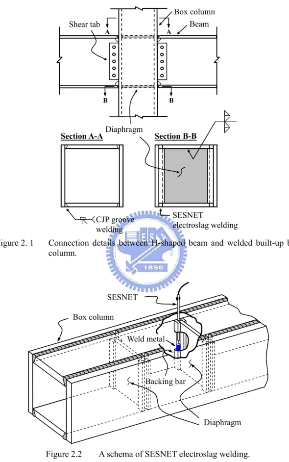
(17) seismic shaking acting in both directions. Therefore, box columns and H-shaped beams have been commonly used for modern steel buildings in some countries such as Taiwan and Japan. Figure 2.1 illustrates the connection details of a box column in practice. Most box columns used in steel constructions are built-up by welding four steel plates using a full penetration groove weld. Diaphragms (or so called continuity plates) are important to the seismic performance of connections, because they have to transfer effectively the beam forces to the column. However, installing such a diaphragm is inherently difficult. A special welding process must be used to weld the diaphragms inside the box column. First, a penetration groove weld is performed to join the diaphragm to a pair of opposite column plates. Then the SESNET (Simplified Electro Slag Welding Process with Non-consumable Elevating Tip) welding process is used to weld the diaphragm to the other pair of column plates. Figure 2.2 shows a schema of the SESNET welding. A non-consumable nozzle, filled suitable fluxes and wires, is inserted in the narrow gaps between the diaphragm and the column plate. Great heat, arising from a short circuit of a high electric resistance of wires, continuously melts the intersection between base metal and wires to achieve an objective of jointing the diaphragm and the box column. Only limited test data concerning the beam-to-box column connections are available. Chen et al. (2004) investigated the cyclic behavior of steel moment connections between H-shaped beams and built-up box columns. Six large-scale specimens were designed and fabricated using a built-up □500×500×35×35 (mm) box column and an H700×300×13×24 (mm) beam. One of the test specimens was the unreinforced connection using pre-Northridge details, and other test specimens were the reinforced connections using rib plates and wing plates. The unreinforced 6.
(18) connection failed due to fracture at the CJP groove weld and near the WAH region during the cycle of 2.3% rad story drift angle. Kim et al. (2004) tested two full-scale moment connections to welded box columns fabricated using pre-Northridge connection details. Test results revealed that both specimens failed by a brittle fracture of CJP weld between the beam flange and the column during a story drift angle of less than 1% rad, which resulted in no plastic rotation in the connections. 2.2.2. Welded reinforced moment connections The intention of welded reinforced moment connections is proposed to reduce. stress and strain demands in the vulnerable region near the face of the column, and to relocate the high plastic strains into the beam. Figure 2.3 shows four types of strengthening schemes commonly used for steel moment connections, including cover plates, wing plates, rib plates, and haunches. More details are described in the following. The approaches of plate-reinforced connections are intended to strengthen the joint by welding cover plates, wing plates or others. Afterward stresses in the CJP groove welds can be reduced because the beam section near the beam-to-column joint is enlarged. Full-scale connection tests of cover plate connections (Engelhardt and Sabol 1998; Kim et al. 2002a, 2002b) showed significant improvement in ductility of the connection. However, some of the test specimens experienced premature failure. An issue based on the experimental research conducted by Engelhardt and Sabol (1998) was raised regarding the presence of weld defects, heat-affected zones (HAZs) due to welding, and the use of excessive reinforcement. A thicker cover plate would result in 7.
(19) the higher potential for weld defects and could cause HAZ problems due to the larger weld area. Figure 2.4 displays the reinforced connections with flat wing plates (陳嘉有 1995). Test results clarified premature crack initiation was observed at the end tips of the weldment between the wing plates and the beam flange, due to the localized stress concentration at the tips of the wing plates. In a rib-reinforced connection, a tapered triangular rib plate is frequently used. Tests conducted by Engelhardt et al. (1995) and Anderson and Duan (1998) demonstrated that connections reinforced with tapered triangular ribs exhibited sufficient hysteretic behavior with plastic rotation ranging from 2.5% to 3.0% rad. Chen et al. (2005a) tested two connections reinforced by a single triangular rib welded to the centerline of each beam flange. One connection failed owing to a brittle fracture in the beam flange at the rib tip, while the other displayed stable hysteretic behavior. Chen et al. (2003, 2004) and 陳誠直等人 (2003) tested other rib-type connections using modified rib plates. A single lengthened rib is welded to each beam flange in the plane of the beam web. Examining the results from the tests presented, it is obvious that the rib-reinforced connection can provide sufficient ductility during the large deformation, with a story drift angle of at least 4% rad and plastic rotation greater than 3% rad. Hysteretic loops demonstrate this moment connection has stable energy dissipation capacity under cyclic loading. Another strengthening scheme is to reinforce the beam around a connection by welding a triangular haunch to the beam bottom flange. Ideally, the beam portion within the haunch region would remain elastic during the large inelastic deformation, so that the stresses in the beam flange groove welds are diminished. Because of this strengthening, redundancy for this type of reinforced connection is much more than that 8.
(20) of reduced beam section (RBS) connection. Uang et al. (2000) tested six full-scale specimens using the welded haunch and RBS for rehabilitation of pre-Northridge moment connections; three of them incorporated lightweight concrete slabs. Welding a triangular haunch beneath the beam bottom flange significantly improved the cyclic performance. 2.2.3. Reduced beam section moment connections The design approach of an RBS connection is similar to that of a reinforced. connection. The RBS is intended to control the formation of plastification moving away from the column face, and to diminish a possibility of brittle fracturing at the beam flange groove welds. In RBS moment connections, portions of the beam flanges are trimmed to force plastic hinging to occur at a desirable location of the beam, whereas reinforced moment connections are made stronger than the beam by strengthening the connections with cover plates, ribs or haunches. The fabrication of the RBS is simple and economical, as compared to the connection reinforcement. However, weakening parts of the beam sections may result in reduction in elastic stiffness of SMFs (Engelhardt et al. 1998). An RBS with small reduction in the beam flanges may do negligible to reduce stress levels in the beam-to-column joint. On the other hand, the RBS with excessive reduction in the beam flanges may cause premature lateral-torsional buckling of the beam in the RBS. Numerous studies and testing have been conducted on RBS moment connections under cyclic loading (Plumier 1997; Chen et al. 1996, 2001; Engelhardt et al. 1998; Popov et al. 1998; Jones et al. 2002; Zhang and Ricles 2006). These investigations primarily focused on three different shapes of RBS cuts such as a constant cut, a radius cut, and a tapered cut (Figure 2.5). The results from laboratory tests demonstrated that 9.
(21) the RBS connection has exhibited acceptable levels of ductility. Nevertheless, small number test data are available about the performance of this type of connection with a welded built-up box column. Chen et al. (1996) conducted successful tests on RBS moment connections with tapered cuts. All specimens were fabricated using a built-up □500×500×20×20 (A572 Grade 50) box column and an H600×300×12×20 (A36) beam. The ductility of the test specimens was significantly enhanced without a striking loss of connection capacity, and an enlarged plastic zone was obtained in the tapered area away from the critical CJP groove weld. 2.2.4. Improvements in connection details Some critical factors could significantly affect the connection performance,. including weld toughness, geometry and size of WAH, and panel zone deformation (Lu et al. 2000). The size and shape of WAH is considered to have dominant effects on the connection behavior. As demonstrated in Figure 1.1, WAHs are needed to be cut on the beam web to perform the CJP flange welding between the beam flange and the column flange. The WAH near the beam top flange is used for placing the steel backing bar whereas the bottom one is used for performing the groove welds. However, the presence of WAH in the beam web causes stress concentration on the center of the beam flange near the root of the WAH region because of the abrupt change in WAH geometry (El-Tawil et al. 2000). As a result, the combination of high stress and strain concentrations results in a brittle fracture at the beam-to-column joints, as documented in laboratory tests (Stojadinović et al. 2000; Chen et al. 2004, 2005a). Figure 2.6 shows two different WAH configurations: one is commonly used in Taiwan; the other is recommended by FEMA-350 (2000). A description of related analytical and experimental studies is presented as follows. 10.
(22) Lu et al. (2000) conducted a series of different WAH configurations using the nonlinear finite element program ABAQUS. Nine various WAH configurations were investigated to evaluate the connection details for fracture potential. The conventional WAH configuration with a circular shape (diameter of 20 mm) was found to have a high concentration of plastic strain in the middle of the beam flange, at the toe of WAH. However, the plastic strain demand of the modified WAH configuration was half that of conventional type, which exhibited the lowest potential for crack initiation among the different WAH configurations. Ricles et al. (2002) tested eleven full-scale interior and exterior welded unreinforced moment connections. All beams used a W36×150 section. The columns used for the exterior connections were a W14×311 section, while W14×395 and W27×258 column sections were used for the interior connections. Test results demonstrated that connections using a high toughness weld metal and modified connection details, including beam web attachment detail and WAH geometry, responded with good connection performance. No fracture near the WAH region was observed during the testing, with a story drifts angle of up to 5% rad being achieved.. 2.3 Proposed Column-Tree Structural Systems with Tapered Flange Connections A column-tree system is one of the constructional schemes used for the SMF. Figure 2.7 demonstrates the column-tree construction. Short pieces of stub beam are fabricated and welded to the column in the shop, forming a column-tree. After the field erection of these tree-like columns, a mid-portion of the link beam is then spliced to the stub beam with bolted connections. This shop welded and field bolted type of the connection is often called “pre-Kobe connection”. Figure 2.8 illustrates two typical 11.
(23) types of column-tree connection. One is the through-diaphragm connection; the other is the interior-diaphragm connection. Of course, fabricating such column-tree connections should be possible to increase costs. Unfortunately, the 1995 Kobe earthquake caused serious failure in some of these typical pre-Kobe moment connections used for the steel column-tree buildings. Since the earthquake, Nakashima et al. (1998) investigated and reported that premature brittle fractures of the beam flanges were found in the beam-to-column flange groove welds where it should have been able to achieve better welding quality. Limited yielding and plastic deformation developed between the columns and the beams was observed in the connections. The unexpected failures raised many doubts regarding a vantage of the quality control on these shop welded-field bolted connections. The use of a widened flange plate (Chen et al. 2006) is one of strengthening schemes to improve the seismic performance of column-tree moment connections. The beam flanges close to the column face are enlarged to reinforce the beam-to-column joint, reducing stress demand at the beam flange groove welds. Figure 2.9 shows the geometry of a widened flange connection used in column-tree SMFs. The details of this connection include a stub beam with widened beam flanges and no weld access hole. Rather than strengthening being provided by a flat triangular stiffener on both sides of the beam flange, a piece of widened flange plate is used to prevent crack initiated in the welding fusion zone between the stiffener and the beam flange. Test results showed that widened flange connections were able to develop satisfactory cyclic performance. Full hysteretic loops of normalized moment versus total plastic rotation, revealed in Figure 2.10, demonstrated this moment connection had stable energy dissipation capacity under cyclic loading. 12.
(24) The purpose of this study is to enhance the ductile behavior of the column-tree moment connection by further improving the geometry of the widened beam flange according to previously related research conducted by Chen et al. (2006). 2.3.1. Design concept Figure 2.11 depicts the configuration of a tapered flange moment connection. The. design objective is to develop a large plastic zone in the beam to enhance the ductile behavior of the moment connection. This intention is achieved by tapering the portion of flange plates in the stub beam along the seismic moment gradient, thus a wide portion of yielding in the tapered zone can possibly provide much energy dissipation. Figure 2.12(a) shows the moment gradient of the flexural capacity and seismic moment demand of the beam. Neglecting the effect of gravity load, the seismic moment demand is the required flexural strength assumed a half-span of the cantilever beam in the moment frame under the seismic condition. Unlike previous studies conducted by Chen et al. (2006) shown in Figure 2.12(b), an extent of large yielding in the beam is intended to develop simultaneously at the overlap of two lines of flexural capacity and seismic moment demand. Furthermore, the beam flange close to the column face has to be enlarged more than the tapered zone of the beam flange to ensure the sufficient capacity at the beam-to-column joint. 2.3.2. Design parameters According to the design idea of the improvements in the connection, two primary. variables governing the behavior of a tapered flange connection are defined as a reinforcement ratio of the tapered flange β j and the length of a tapered part Ltap , respectively. Figure 2.11 indicates these design variables. The parameter β j is a main 13.
(25) reinforcement factor at the beam-to-column joint and is defined as a ratio of the flexural capacity, M p , j , to the seismic moment demand, M dem, j (i.e., β j = M p , j / M dem, j ),. ensuring sufficient safety at the column face. Another primary parameter Ltap represents the length of the tapered region of the beam flange and purposes to provide a larger deformation capacity in the beam. There are remaining variables: the length of a main reinforced part Lw1 , the length of a curved transition part Lw 2 , and the length of an extension part Lext . Lw1 is used to assure the plastic deformation of the beam moving away from the critical beam-to-column interface. Considering the effect of force transferring from the main reinforced part to the tapered flange smoothly, the curved transition Lw 2 of 50 mm is used in this study. The tapered flange extension Lext proposes to reduce the stress and the strain demand on the splice joint between the column-tree and the link beam, preventing the occurrence of the unexpected fracture. Due to the complexity of force transfer mechanism within the connection region, detailed parametric studies are needed to clarify the effect of each design parameter on the behavior of a tapered flange connection, as presented in Chapter 3.. 14.
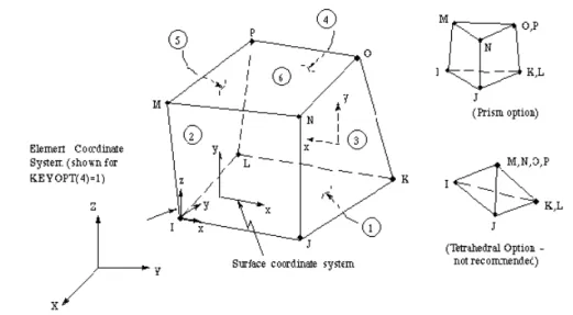
(26) Chapter 3.. Parametric Study. 3.1 General Finite element analysis is currently in widespread use in not only aeronautic structures but also mechanical and civil engineering structures. Analytical results would become more authentic through an assumption of realistic material properties and a validation of analytical modeling. A previous analytical study conducted by Chen et al. (2005b) had shown that both global and local responses of the connection subassemblage could be simulated accurately using nonlinear finite element models. Accordingly, the general-purpose nonlinear finite element analysis program ANSYS (2002) was utilized to model the varied configurations of the tapered flange connection and further to study the effects of design variables on the connection behavior.. 3.2 Analytical Model Description 3.2.1. Finite element modeling. The finite element models of connection subassemblage, consisting of three-dimensional structural solid elements with 24 nodal degrees of freedom (Figure 3.1), were used in the analytical study. The connection subassemblage represents an exterior T-shaped connection isolated from a moment frame. Figure 3.2 shows the finite element meshes and boundary conditions of the typical analytical model. For a SMF under a lateral loading, the inflection points of the column and the beam are generally assumed to occur at the mid-height of the column and the half-span of the beam. So that in the finite element analysis roller and pinned supports were modeled at each end of the column, as well as a monotonic incremented displacement was applied to the beam. 15.
(27) tip. Furthermore, due to the structural symmetry with respect to the mid-plane at the beam web and the column section, only half of the connection subassemblage was modeled to decrease the computational effort. Each of models consist of a H-shaped H700×300×13×24 (dimensions in mm for depth, width, web thickness, and flange thickness, respectively) beam, having a length of 3,600 mm from the beam end to the column face, and a box □550×550×28×28 column, 3,000 mm long between the hinged supports at the ends of the column. The conventional WAH configuration with a quarter-circular shape, as shown in Figure 3.3, was included in the models to evaluate the local effect of the connection details. Meanwhile, the root of the CJP single bevel groove welds located on the interior sides of both top and bottom flange was modeled to simulate the pre-Kobe connection details. However, backing bars and runoff tabs did not include in the models. A series of seventeen finite element models was designed and selected for detailed evaluation, as listed in Table 3.1. An unreinforced connection was modeled to represent the pre-Kobe column-tree moment connection, to clarify the improvement of the tapered beam flange on the connection behavior. Other finite element models with different configurations were designed to reveal other design variables. A control model of tapered flange connection used the following design properties: (1) β j =1.2; (2) Ltap =0.3 d b (210 mm length); (3) Lw1 =0.5 b f (150 mm length from the column face); (4) Lw 2 =50 mm; 16.
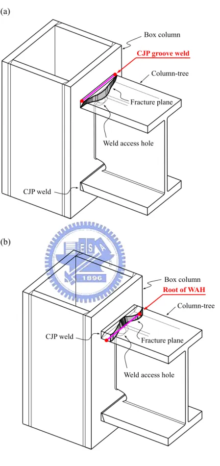
(28) (5) Lext =0.5 d b (350 mm length from the end of the stub beam) where b f is the width of the beam flange; and d b is the depth of the beam section. The remaining models changed one parameter at a time from among parameters to eliminate the interactive effects between these parameters. Table 3.1 tabulates dimensions of the tapered flange used in the models that had the width of the flange enlargement ranging from 372 to 530 mm and the length of the stub beam ranging from 410 to 1110 mm. 3.2.2. Performance indicators. The potential for cracking is evaluated through a tendency of stress and strain states at different levels of a story drift angle. Hence, the principal stress is used to assess the stress distribution in the elastic range, as well as the plastic equivalent strain (PEEQ) is also employed to criticize the local plastic strain demand in the inelastic range. The plastic equivalent strain is defined as. PEEQ =. 2 ε ij ε ij 3. (3.1). where ε ij represents plastic strain components in directions i and j . Undoubtedly, higher PEEQ reveals a higher demand for plastic strain. Meanwhile, these two stress and strain indicators are normalized for the purpose of indicating their inclination clearly: the principal stress is normalized by the yield strength Fy , while the PEEQ is divided by the yield strain ε y defined as the PEEQ index. Two critical sections of the connection, along the beam flange width at the locations of the CJP groove weld and the root of the WAH, are selected to study the 17.
(29) stress and strain statuses based on the fracturing locations in the pre-Kobe moment connections reported in Nakashima et al. (1998). Figure 3.4 displays these critical sections, presented by lines running across the width of the beam flange. Besides, story drift angles of 0.5% and 4% rad are chosen to study the elastic behavior and high plastic deformation state of the connection subassemblage, respectively. 3.2.3. Material properties. Nominal yield stress of A572 Grade 50 steel used to model the beam and column was set equal to 345 MPa. The expected material overstrength factor R y recommended in AISC (2005a) was also considered to simulate the realistic material properties of the steel. For simplification, a bilinear isotropic hardening behavior was used for simulating the stress-strain relations of the structural steel and the weld; a rate-independent plasticity model was especially used in the inelastic behavior. The modulus in the strain-hardening range of the steel and the weld adopted 3% and 1.5% of the modulus of the elasticity, respectively. Besides, to determine the plastification of the analysis models, von Mises yielding criterion with the associated flow rule and the isotropic hardening rule was used.. 3.3 Parametric Study of Tapered Flange Connection Finite element analysis can provide better preliminary evaluation of stress and strain states in tapered flange connections and to compare behaviors of connection configurations relative to different design parameters. A set of parametric analyses, therefore, was conducted to investigate the effectiveness of the tapered flange connection.. 18.
(30) 3.3.1. Effect of tapered flange on connection behavior. Figure 3.5 demonstrates the normalized principal stresses at 0.5% rad story drift angle and PEEQ indices at 4% rad story drift angle along the width of the beam flange, at the CJP groove weld and the root of the WAH. It should be noticed that the tapered flange connection model was a control model using parameters that had been mentioned previously. Both connections show high stress concentration at the tips of the groove weld during a story drift angle of 0.5% rad, owing to the distribution of stiffness contributed from the cross section of the box column. An identical phenomenon was observed in the middle of the beam flange, at the root of the WAH, because of the unevenly geometry of the WAH shape. However, when the tapered flange connection model proceeded to the inelastic range of 4% rad story drift, 62.5% and 42.4% reduction rates of the maximum PEEQ indices at the edges of the groove weld and at the root of the WAH were obtained, respectively, compared to the pre-Kobe connection model. Certainly, the presence of the enlarged beam flange considerably reduced the high concentration of plastic strain at the beam-to-column interface and the WAH region, diminishing the potential fracture at these locations. Effects of parameter β j and length of tapered zone Ltap. 3.3.2. Four different values of β j were studied to elucidate the effect of the reinforcement ratio of the tapered flange on the response of the connection subassemblage. The reinforcement ratios were set equal to 1.05, 1.10, 1.20, and 1.25, with the width of the flange enlargement in the range of 344 to 530 mm. Additionally, to clarify the influence of the plasticity capacity in the tapered zone of the beam flange on the connection performance, design parameter Ltap was varied by changing the 19.
(31) region in the tapered zone from 0.3 d b to 0.8 d b (dimensions ranging from 210 to 560 mm). The analytical results are summarized in Figure 3.6, where the values of the PEEQ indices at 4% rad story drift angle were captured from the critical locations of the beam flange groove weld and the root of the WAH. The PEEQ index is shown to be largest for the traditional pre-Kobe column-tree connection. It is obvious that the higher flange reinforcement causes the lower plastic strain demand; furthermore, using the larger tapered zone can also result in lower PEEQ index. With the value of β j larger than 1.2, increasing the length of the tapered zone from 0.3 d b to 0.8 d b has a slight variation in the improvement of the local plastic strain demands. Overall, higher parameter β j increasing the deformation capacity of the groove welds results in higher margin of safety at the junction of the beam-to-column connection. Effect of main reinforced part Lw1. 3.3.3. Considering a plastic hinge formed a sufficient distance away from the column face, the lengths of a main reinforced part are set equal to 0.17 b f , 0.33 b f , and 0.5 b f for the models, with the corresponding lengths are 50 mm, 100 mm, and 150 mm, respectively. Figure 3.7 demonstrates the effects of the different values Lw1 on PEEQ indices at a story drift angle of 4% rad. Results show that the model with smaller Lw1 have higher PEEQ index at the root of the WAH, compared with the model with larger Lw1 ; the maximum PEEQ index decreases from 15.4 to 12.5, a decrease of 18.8%, as the main reinforced zone Lw1 increase from 50 mm to 150 mm. However, a reverse tendency was noted in the CJP groove weld; an increase of 15.4 % of the maximum PEEQ index was observed (increased from 9.1 to 10.5). In sum, the larger tapered. 20.
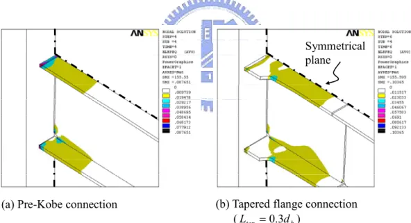
(32) flange reinforced zone Lw1 results in lower plastic strain demand at the WAH region. Effect of tapered flange extension Lext. 3.3.4. Three different lengths of a tapered flange extension, 0.25 d b , 0.5 d b and no extension part, were used for prospecting the influence of the splice, at the joint of the column-tree and the link beam, on the tapered flange connection. The distributions of PEEQ index across the beam flange at the tip of the WAH are presented in Figure 3.8. The largest value of the PEEQ index occurred at the root of the WAH (pointed at Figure 3.8) for the model without the extension part because the vicinity of the tapered zone also had high deformation demand. Nevertheless, a reduction of 38.9% in the PEEQ index of the model with Lext =0.5 d b was observed at the same location. It is expected that larger flange extension Lext can ensure higher safety capacity at the interface of the column-tree and the link beam. 3.3.5. Plastification of tapered flange connection. Figure 3.9 and Figure 3.10 present the contours of the longitudinal plastic strain and the plastic equivalent strain at a story drift of 4% rad, respectively, to clarify the spread of the plasticity around the connection. Remarkably, the tapered flange connection demonstrated extensive plastification and significant yielding beyond the tapered region, whereas the localized plastic hinge formation took place close to the beam-to-column interface was observed in the pre-Kobe connection. Based on these observations shown in figures, indeed, tapering part of the flange plate following the seismic moment demand conduced to the formation of the extensive plasticity in the beam section away from the column face.. 21.
(33) Chapter 4.. Full-Scale Connection Tests. 4.1 General The analytical program in Chapter 3 presented the investigation concerning the connections with different configurations of the tapered flange. However, such analyses have some limitations such as residual stresses and HAZ problems in beams that cannot be modeled perfectly. Seven full-scale exterior beam-to-column connections were, therefore, designed and tested to clarify the cyclic behavior and failure modes of tapered flange connections.. 4.2 Design of Test Specimens The designs of all specimens followed the current AISC specification (2005b) and the Taiwanese seismic code. The specimens had identical sections of the beam and the column to eliminate the influence of the member size on the connection behavior. The beam and the column were ASTM A572 Grade 50 H-shaped H700×300×13×24 (mm) and box □550×550×28×28 (mm) sections, respectively. Table 4.1 presents the mechanical properties of the steel used for specimens, which were obtained from tensile coupon tests. The CJP groove welds between the column flange and the beam flanges for all specimens were done by the gas metal arc welding (GMAW) process, using an electrode of ER70S-G filler metal. Table 4.2 tabulated the design parameters of the specimens. Tests began with a specimen with a traditional pre-Kobe moment connection, to examine the performance of the welded column-tree connection. Figure 4.1 depicts the connection details of specimen PK. Specimens W1-L05, W1-L03, W2-L03 and W3-L03 were constructed. 22.
(34) following pre-Kobe design practice, whereas various beam web attachment details were designed for specimens B1-L03 and B2-L03 to reflect pre-Northridge design practice. In the labeling of the specimens, the first character, W, presents fillet welded beam web and the second character, B, represents bolted shear tab. Specimen fabrications in Series W and Series B are described in following two sections in detail. Specimens of Series W. Figure 4.2 illustrates the details of the tapered flange specimens of Series W. Specimens’ designation with W1, W2, and W3 indicates β j =1.20, 1.10, and 1.05, respectively, which results in a different width of beam flange at the beam-to-column interface. Especially, the narrower flange enlargement of specimen W3-L03 was conducted to represent a more critical state. To clarify the plastic deformation capacity, the lengths of the tapered flange Ltap were set to 0.3 d b and 0.5 d b , and the corresponding specimens were designated as “L03” and “L05”, respectively. The tapered beam flanges were fabricated by a thermal cutting process from a steel plate, to avoid crack initiation in the fusion zone of the groove welds between the wing plates and the beam flanges (Chen et al. 2004). It is noted that the splice between the stub beam and the link beam was fully welded in the laboratory to prevent the slippage effect of the bolted splice. The width/thickness ratios b f / 2t f of tapered flanges are checked for compacted. sections used for beams in a SMF. The maximum b f / 2t f ratio of the beam flange in the tapered zone is 7.2, which is less than the limiting value λ p (= 171 / Fy (MPa) = 65 / Fy (ksi) =8.9) of the AISC specification (2005b) for compression members,. 23.
(35) being capable of achieving the large plastic strain without local buckling occurred. Specimens of Series B. The geometry and size of the tapered flange in specimens B1-L03 and B2-L03 are the same as those in specimens W1-L03 and W2-L03 except the beam web attachment. Figure 4.3 shows the specimen configurations of Series B that the beam was connected to the column with the web-bolted flange-welded connection. A short piece of tapered flange beam was built up in the shop and was further spliced to the remaining beam to make one piece of the beam. Afterward a shear tab and beam flange groove welds were used to connect the beam and column together: the CJP groove welds were connected the beam flange to the column flange; the beam web was connected to the shear tab by F10T M24 high-strength bolts. No supplementary fillet weld was placed around the edges of the shear tab.. 4.3 Test Setup and Procedure Tests were conducted in structural laboratory of the National Chiao Tung University. Figure 4.4 illustrates the test setup which simulated the seismic condition of a connection subassemblage in a moment frame. A hydraulic actuator, which has the capacity of the maximum load of 980 kN and stroke of 400 mm, was used to proceed this cyclic routine. As shown Figure 4.5, a cyclic predetermined loading sequence with augmented displacement amplitudes specified in the AISC seismic provisions (2005a) was used during the tests. The test history began with six cycles of ± 0.375, ± 0.5, and ± 0.75% rad story drift angle. Subsequently, four cycles of ± 1% rad story drift angle. and two cycles with amplitudes of over ± 1.5% rad story drift angle were succeeded 24.
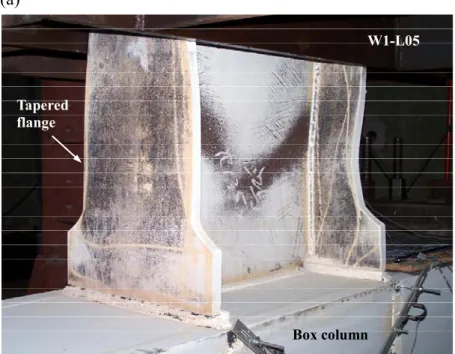
(36) until either the specimens failed or the excursion limitation of the test equipment was reached. It should be noted that the story drift angle is calculated by dividing the beam tip displacement by the distance from the beam tip to the column centerline, as shown in Figure 4.6.. 4.4 Observed Behavior of Test Specimens 4.4.1. Specimen PK. Specimen PK was a typical pre-Kobe column-tree moment connection. Flaking of the whitewash originated from the sides of the beam flanges near the groove welds during a story drift of 0.5% rad, and significantly concentrated on this location at the following cycles. This clearly evidences that the beam flange close to the column face develops high local strain concentration, as observed in the finite element analysis. Afterward the slight cracks were noticed in the fusion zone of the borders of the CJP groove weld at the cycles of 3% rad story drift angle. Eventually, specimen PK failed during the negative excursion of the first 4% rad cycle because of a brittle flange fracture, which initiated at the root of WAH cut on the inside of the beam flange surface, as presented in Figure 4.7. 4.4.2. Specimens of Series W. Excluding specimen W3-L03, the failure mechanisms of all tapered flange specimens were almost identical regardless of the various configurations of the flange enlargement, as listed in Table 4.3. All of four specimens exhibited approximately linear behavior before a story drift angle of 0.75% rad because slight powdering of the whitewash was observed in these states. During the cycles of 1% rad story drift angle, the whitewash was noticed on the beam flanges within the tapered part and near the CJP 25.
(37) groove welds. The following cycles of 1.5% rad story drift angle caused flaking further expanding into the tapered flange extension. After that, the whitewash began to spread in the beam web at the 2% rad cycles. Evidenced by the excessive flaking of the whitewash, the overall beam tapered flanges and the beam web developed striking inelastic behavior during the cycles of 3% rad story drift angle. Unexpectedly, minor cracks, either at the sides of beam flange groove welds or at the root of WAH, were observed during the 3% rad cycles of specimen W3-L03; however, no cracking occurred in the other specimens at the same cycle. The sign of cracks apparently revealed that the specimen W3-L03, with β j =1.05, provided very margin of the reinforcement at the beam-to-column joint. Afterward, sustained crack propagation led to the fracture of the beam bottom flange, starting at the fusion area of the groove weld as shown in Figure 4.8, during the positive excursion of the second 4% rad cycle. The ultimate strength of the specimens was achieved during the cycles of 4% rad story drift angle, which simultaneously accompanied slight crack initiation from the end of the built-up weld fusion line between the beam flange and web at the root of WAH. Excessive local buckling of the beam section, developed at approximately ranged from one-half to three-quarter the beam depth from the column face, resulted in gradual deterioration of the strength during the following cycles of 5% rad story drift angle. Figure 4.9 shows local buckling of the beam flange and the beam web of specimens W1-L05 and W1-L03 at a story drift angle of 5% rad. Test was terminated at a story drift angle of 5% rad because of the excursion limitation of the actuator. To sum up, for the properly designed specimens, the plastic hinge formation of the beam was expectably spread around the tapered flange, developing the satisfactory plastic rotation of the connection.. 26.
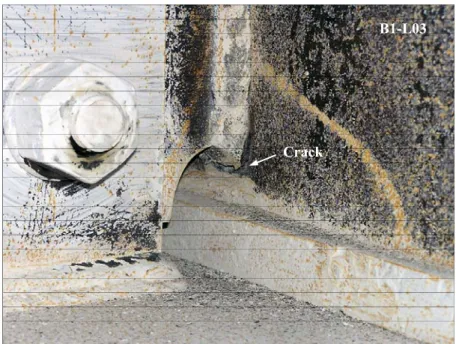
(38) 4.4.3. Specimens of Series B. Both specimens performed the same patterns of global behavior with each cycles until at 3% rad story drift angle. The flaking of the whitewash was noticed on the tips of the shear tab near the WAH, accompanied a metallic grating noise caused by the shear tab slippage. During 4% rad story drift angle, the ultimate resisting force of the connection was reached while minor cracking was observed at the root of WAH, as shown in Figure 4.10. At the same time, the progressive augmented buckling of the beam section, stemming from the tapered part of the beam flange, caused strength degradation in specimen capacity during subsequent cycles. Figure 4.11 exhibits the yielding and local buckling patterns of specimens B1-L03 and B2-L03 during 5% rad story drift angle. The presence of the shear tab not only assisted in forming the plastic deformation in the beam away from the column face but also resisted the occurrence of the severe web local buckling. Finally, testing was stopped at 5% rad story drift angle due to the displacement limit of the test apparatus. No weld fracture was observed in the specimens except a small crack, which was located in the HAZ at the edges of the beam top flange, at the end of the test of specimen B2-L03.. 4.5 Test Results and Discussion Test results of the specimens are inspected for the hysteretic response, the failure modes, the connection moment capacity, the envelope response, and energy dissipation. Table 4.3 tabulates the test results of the specimens. 4.5.1. Hysteretic response and failure modes. Specimen PK. 27.
(39) Figure 4.12 presents the hysteresis relationships of specimen PK in terms of both the story drift angle and the total plastic rotation. Herein, the test moment was calculated by multiplying the beam tip load by the distance from the free end of the cantilever beam to the box column face, and this moment was normalized by the plastic moment capacity of the stub beam based on the measured material strengths. The maximum total plastic rotation of specimen PK was 2.6% rad, which the total plastic rotation was determined by subtracting the elastic rotation from the total angle of rotation. The failure was caused by the fracture of the beam flange initiated at the junction of WAH and the beam flange groove weld. Although the ductility of this specimen was improved, compared to the pre-Northridge specimens tested by Chen et al. (2004), using column-tree design practice in the connection has insignificant effect on the prevention of the beam flange fracture originated from the WAH region. Specimens of Series W. The hysteresis responses of the normalized moment to the story drift angle and the total plastic rotation for the all column-tree tapered flange specimens are presented in Figure 4.13. As summarized in Table 4.3, specimens W1-L05, W1-L03, and W2-L03 developed approximately 4% rad of maximum total plastic rotation, which contributed mainly from the inelastic deformation of the beam. The beam plastic rotation was determined by subtracting the plastic rotations of the column and the panel zone from the total plastic rotation of the connection. The primary failure mode of these specimens was the significant local buckling of the beam flanges and web, which was followed by the degradation of connection strength, during the cycles of 5% rad story drift angle. The post-peak strength capacity of specimens W1-L05, W1-L03, and W2-L03 were reduced by 15.6% (an average of +13.5% and -17.6%), 17.3% (an 28.
(40) average of +18.8% and -15.8%), and 17.1% (an average of +16.8% and -17.4%), respectively, compared to those at the 4% rad cycles, where ‘+’ represents the positive excursion cycle and ‘-’ represents the negative excursion cycle. As shown in Figure 4.13(a), specimen W3-L03 failed in a brittle mode caused by the fracturing of the beam bottom flange during the cycles of 4% story drift angle. After that, the negative excursion of monotonic loading was applied to identify the failure mode in the beam top flange. In the end, not only local buckling of the beam bottom flange was noticed within the tapered zone of the beam flange, but also notable cracks either at the root of WAH or at the both sides of the beam flange groove welds were observed at the end of the testing. Specimens of Series B. The cyclic behavior of the specimens B1-L03 and B2-L03 behaved much like those column-tree connections regardless of their various connection details. A graph of the hysteresis relationships for specimens B1-L03 and B2-L03 is shown in Figure 4.14. Both specimens developed reliable inelastic behavior with a maximum story drift angle of 5% rad, absorbing a remarkable amount of the energy. The final failure was owing to striking local buckling at the beam flanges and web, and accompanied gradual deterioration in the flexural strength of the connection. However, the strength still exceeded the plastic flexural strength of the beam. In brief, the pre-Northridge specimens improved by the tapered flange behaved excellent ductile performance, although the extra cost for fabricating such built-up tapered flange connection is relatively high, compared to those typical web-bolted flange-welded moment connection.. 29.
數據
+7


相關文件
Murphy.Woodward.Stoltzfus.. 17) The pressure exerted by a column of liquid is equal to the product of the height of the column times the gravitational constant times the density of
Students are asked to collect information (including materials from books, pamphlet from Environmental Protection Department...etc.) of the possible effects of pollution on our
Then, it is easy to see that there are 9 problems for which the iterative numbers of the algorithm using ψ α,θ,p in the case of θ = 1 and p = 3 are less than the one of the
By correcting for the speed of individual test takers, it is possible to reveal systematic differences between the items in a test, which were modeled by item discrimination and
We explicitly saw the dimensional reason for the occurrence of the magnetic catalysis on the basis of the scaling argument. However, the precise form of gap depends
Miroslav Fiedler, Praha, Algebraic connectivity of graphs, Czechoslovak Mathematical Journal 23 (98) 1973,
Microphone and 600 ohm line conduits shall be mechanically and electrically connected to receptacle boxes and electrically grounded to the audio system ground point.. Lines in
Establish a check and balance mechanism to ensure that fee remission is offered in accordance with the school-based eligibility criteria, which should be no less favourable than
