Proceedings of the American Control Conference Albuquerque, New Mexico June 1997
0-7803-3a32-41971$10.00
o
I 997 AACCNONLINEAR ADAPTIVE SPEED AND TORQUE SERVO CONTROL
OF INDUCTION MOTORS WITH UNKNOWN ROTOR RESISTANCE
An-Ming Lee
Li-Chen
F'u
Department
of
Electrical Engineering'
Department
of
Computer Science and Information Engineering2
National Taiwan University
Taipei, Taiwan, Republic
of
China
Abstract: In this paper, we propose a nonlinear adaptive speed and torque controller of induction motors with
unknown rotor resistance. All the system parameters except rotor resistance are assumed t o be known and only the stator currents and rotor speed are assumed t o be available. T h e desired speed and torque should be any continuously differentiable bounded function.
A
complete proof of the global stability without singularity is given and the output error will converge to zero asymptotically. Finally, the simulation and experimental results will be given to demonstrate the effectiveness.Nomenclature
V,
( 6 )
: a-axis (b-axis) stator voltage, I, ( I * ) : a-axis (b-axis) stator current, $a ($a) : a-axis (b-axis) rotor flux, w, : mechanical angular speed of rotor, R, : stator resistance,R,
: equivalent rotor resistance,L ,
: stator self-inductance,L ,
: equivalent rotor self-inductance,M
: mutual inductance, p : number of pole-pairs,J
: rotor inertia,D
: damping coefficient,TL
: load torque, kT: torque constant
L ,
:$ ( L ~
-
cl,
M Z :y,
pz
: pL,, p 3 :g
L aIntroduction
In recent years, due to the great advances in nonlin- ear control theory, the observer-based controller has be- come one of the most commonly used scheme in induc- tion motor control and enormous amount of results on this have been published. Instead of measuring the ro-
tor fluxes directly, the flux observers were constructed to furnish flux estimates needed in the controller. First of all, Kanellakopoulos et al. [4] proposed a nonlinear flux-observer based speed control with known motor pa- rameters. Then, a variety of related reseraches have also been presented [l] [9] [13].
All the control schemes mentioned above are greatly dependent on the exact knowledge of the motor param-
sufficient robustness, the comtemporary design of the in- duction motor controller should take the uncertainties of motor parameters into account. In [lo], Marino et al. proposed a clever adaptive observer scheme which could compensate for the unknown but bounded rotor resis- tance. Later, Hu et al. [3] slightly modified the above observer structure and provided a rigorous proof for speed/position control with uncertain mechanical sub- system. But it was still subject t o a singularity problem when the magnitude of the estimated rotor flux is zero.
For torque control problem, many results have been presented and have obtained satisfactory performance. In [2], Espinosa et al. proposed a globally stable output- feedback speed tracking controller for induction motors without any estimation of the rotor fluxes. But this scheme needs t o know exact values of the motor param- eters.
In this paper, we will propose a new nonlinear adap- tive speed and torque controller with unknown rotor re- sistance, which is free of singularity problem. Only the stator currents and rotor speed are assumed available for the design. A complete Lyapunov-based proof is provided which shows that the errors of speed and torque track- ing will asymptotically approach to zero. T h e simula- tion as well as the experimental results are also presented to demonstrate the performance of the hereby developed controller.
servers and controller design are developed, in which the asymptotical speed and torque tracking will be proved. T h e simulations as well as the experimental results of the control performance are given in section 3. Finally, we will make some conclusions in section 4.
1
Preliminary and Problem
For-
mulat ion
If the induction motor is assumed to be linear, i.e., i t is never in the saturation region, and the waveform of air- gap M M F is nearly sinusoidal, then the dynamic equa- tions can be expressed as follows [6] [3]:
L o I a
L o I b = -MRrIb - PlIb
-
h w r $ ' a+
R r $ ' b P 3 v b= -MRrIa - P d a
+
%$'a+
P2wr$'b+
P 3 v aL,$'a
= -&$ai-
MRrIa - p2wr$'bLc,?)b
=
-Rr$'b -I-MRrIb
-I- PZWr$'aTe = k T ( $ a I b - $ b l a ) (1)
where
L o ,
PI,
/32, P3 are constants defined in the Nomen- clature. In the above equations, ( I a , Ib,G a ,
$'b) are referred to as the well-known stator fixed a-b model as presented in [3]. Moreover, t o facilitate our subsequent controller design which intends t o relax the need of the knowledge of the rotor resistance R,, the terms associ- ated withR,
are seperated from the other terms in the system dynamic equations.2
Induction Motors Control
Before we proceed with the controller design and its anal- ysis, some practical assupmtions will be made below :
Assumptions:
( A l )
All
the parameters of the motor except the rotor resistanceR,
are known. (A2) The stator currents and rotor speed are measurable signals. (A3) T h e rotor resis- tanceR,
is an unknown but its upper and lower bounds are priorly known, i.e.,l
?
,
<
R,
<
R,
for some known constants
R,
and R , . (A4) T h e de- sired torque should be bounded continuously differen- tiable, i.e., T d E BC'. (A5) The load torque TL is a function which satisfies that, ifT,
is bounded, then therotor speed wT is also bounded.
Due t o the fact that the flux signals are not measur- able, the nonlinear adaptive controller proposed here will have t o involve state observation and hence the observer design. Motivated by the observer scheme in [3], in ad- dition t o the flux observers, we construct the current ob-
servers which takes the unknown rotor resistance into account.
Let the state observers be designed as follows :
Lr&b = -&$b
+
M&Ib+
,&Wr$a+
2104+
Ue4 and define. . - ~I
Ta E I a - I a , Ib = Ib- I b t $'a
=
$'a - $ a , G b =I $b-'$'b8 a
Lo?, $- L r G a , z b Lo?b -I- L r G b , Rr R, -A,
therefore
-
-Za
=
- k o I a - ~ 0 1 - u C ~- 2103 -I I
zb
= -koIb - U 0 2 - U c 2 - U04 - U c 4Apparently, the signals
2,
and2b
are measurable since1,
andIb
are measurable.In order to eliminate the appearance of the uncertain parameter as well as the unmeasurable states, such as
R,,
J a and&,,
we can design the following auxiliary signals related to the observation error :q a
=
z a -(a+
f a , q b gb - (^b+
f bwhere € 0 , E b are the errors caused by the initial conditions and
€ a
=
r ] a ( o )+
( a ( 0 ) - z a ( o ) , f b qb(0)+
C b ( 0 ) - Z b ( 0 )Because Z a ( O ) , j b ( 0 ) are not priorly known, f a and fb
can be regarded as some unknown constants.
Define the state variables in a more compact form :
then the state equations can be written concisely in a matrix form as follows:
i
= (A0+
&)a:+
B u where0 0 MR, L ,
I
0
0 0 0 MR, L ,Remark:
From the foregoing compact redefinition, wecan make observe t h a t , A0 is a negative-definite matrix, so that
zTAoa:
<
0Lemma
1
If the desired torque Td can be expressed in the following form :
Td
= kT($'adIbd-
$ b d I a d ) ,then the bound on the difference between the electrical torque and the desired torque can be expressed as follows
Proof:
Refer t o [2] 0
Corollary
1
If the state error e -+
0
ast
-+ 00, thenT,
---f T d ast - + m
Theorem
1
Consider an induction motor whose dynamics are gov- erned by (1) under the assumptions (Al)-(A5). Then the output torque T, will approach t o the desired torque T d asymptotically by the following controller :
Lo
1 - - P 2P3 Lo L o
'
M -
P1L o L O
U 1
=
- ( - - R r $ a - - W r ? J b+
I a d+
- & l a d+
- I a d-
klel $- u1)M P1
L O L O
+
i b d+
- R r I b d+
- I b d-
kle2+
v2)for some constant k l
>
0 , where1 1
LOL, LOL,
ul
=
- & ( L o f a-
(a), 212=
- & ( L o f b-
( b )and the auxiliary control inputs are designed as the fol- lowing form : u c 1 = -Louc3, u c 2 = -Louc4 P 2 w,e2 uc4 = 91- P 2 L, L o L ~ L ~ ~ ~ ~ ~ u c 3
=
-g1-for some constants ko, g 1
>
0 , with the following param- eter adaptation law :if R,
>
R r+
61I
6 2 ifRr
=R,
+
61subject t o & ( O )
>
R,
+
6 1 , and for some constantsr r p r
+
+ g 2 y 2 a 2 ( ~ ,-
R,))
R, =
6 1 , 6 2 , g 2 , 7
>
0.Proof
Select the Lyapunov function candidate as follows :
1 1 1 - 1 2 2 2 2
v
= -Lo%+
-Lo?;+
-2,"
+
-2;
1 1 1 1+
s & ( q a-
fa)'+
s % ( q b-
fb)'+
-r;'R;
2+
-eTGe,
2G
=
diag [ S l , 91, g 2 , s21for some constants
I?;',
91 g 2>
0 , then its time deriva- tive is obviously the following form :where
By assigning 91, 9 2 properly,
V
2
0
and V_<
0,
it can be shown thatTu,
f b ,i,,
z b andvu,
v b ,R,.,
e l , e 2 , e 3 , e4 are all bounded. From Corollary 2 , I , d , I b d , ?+badl $bd are bounded, and henceI , , I , ,
,
z b ,it is obvious that
6,
and&,
are also bounded. Since the true states and the estimated errors are all bounded, then the state estimations6 ,
f b ,Ga, &,
are also bounded.Therefore, all the internal signals, and hence the signal
T,
as well as w r , , are bounded, and, especially by the as- sumption(A5),
f a ,
f b and 151, e 2 ,&, &
are all bounded as well.As a consequence, all the input design is indeed a fea- sible design and by Barbalat's Lemma, it can be shown that
,
$ b are also bounded. By definitions ofF a , f b , e l , e21 e 3 , e 4
-0,
ast
--+ 00 (3)and, according to the results of Lemma 1,
This shows that the objective of torque tracking is thus achieved.
2.1
Speed Control
For the rotating machines, such as induction motors, the rotor speed w, is the function of electrical torque and load torque, which can be expressed as follows :
JW,
+
Dw,=
T, - TL(5)
where J
>
0 is the rotor inertia and D>
0 is the damping coefficient. Therefore, in order to achieve speed control of the induction motor, we should first take the effect of T t into account. In this paper, as mentioned in assump- tion (A5), the load torque TL is assumed to be a known function of the rotor speed, which can be expressed as follows :TL =
PO ' ~ ( k , W r )+
p1wr+
p2br (6)for some known contants k , po, 1.11, pz
>
0. Since we have successfully proposed a global asymptical torque controller in the previous subsections, it is natural toutilize this controller to achieve the speed control. By substituting (6) into (5), the electrical torque Te can be re-expressed as follows :
T e (J
+
~ 2 ) b r+
(D
+
p l ) w r + P O.
s ( k , W r ) ( 7 )Define the desired torque T d as the following form :
T d
=
( J+
p 2 ) W r d+
( D
+
p 1 ) w r d+
PO ' s ( k , u r d )(8)
where W r d
is
the desired speed trajectory. Subtract(7)
from(8),
we can obtain( J + P 2 ) ~ 5 + ( D + / l l ) e 5 + p O [ s ( k , W r ) - S ( k , u r d ) ]
=
T e - T d(9) where e5
=
wr - u r d . If is an arbitrary bounded,second-order continuously differentiable function, then
T d from (8) obviously satisfies the assumption (A4). In
the following, we will present a theorem which describes conditions under which wr will approach to U r d asymp-
totically.
(A6) T h e disired rotor speed should be a bounded, second-order continuously differentiable function, i.e., W r d E
B C 2 ,
such that Td satisfies (A4).Theorem 2
Consider an induction motor whose dynamics are gov- erned by (1) under the assumptions (Al)-(A3) and (A5)- (A6). If the desired torque T d is defined as the following
form :
T d = ( J f p 2 ) b r d
+
(D
+
p 1 ) u r d+
PO ' s ( k , u r d ) Then the rotor speed wr will approach to W r d asymptot-ically by the controller as same as that of Theorem 1.
Proof
Since the sigmoidal function s ( k , z) is defined as follows
9
P
s ( k , z)
=
- 1 1+
e - k . xthen its first-order derivative g ( k , z) can be found as :
2 k e - k ' x g(k7 = + e - k . x ) 2
it is obvious that 0
5
g ( k , z)5
$.
From the Mean-Value theorem, it can be shown thatwhere w E [ w r , w r d ] , and hence, (9) can be re-expressed
as follows :
T e
-
T d = ( J+
pa)&+
( D + p i+
g ( k ,Since (Te
-
T d ) is bounded and approaches to 0 asymp- totically. Then, e ( t ) will approach to 0 asymptotically, that is, wy. will approach to W r d asymptotically. 03
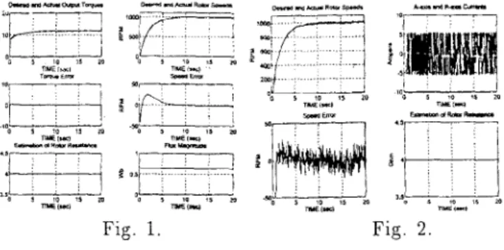
Simulation
Result
A &pole, 1 horsepower, three-phase induction motor with
a squirrel-cage rotor is used which is equipped with a
1024 pulse/rev encoder. T h e motor is manufactured by
ELMA
MOTORS
CO.
with delta-connected stator and the specifications are given below :Rated current
=
4h, Rated voltage = 220V, Rated fre- quency =60Hz,
Rated Speed =1120RPM,
R,
= 3.745Q2,R,
= 3.583Q, L , = 163.3mH,L ,
= 163.3mH, ill=
154.67mH, J = 0 . 0 5 N . n ~ 'T h e control gains are
k
= 20,ko
=10,
ICl = 100, 61=
T h e result is in Fig.1 with U r d =lOOO(1
-
e-"'') rpm and5N
. m load torque.0, 6 2 = 20, 91
0.05,
g:! 20, = 0.15, 7 = 0.67.Fig. 1. Fig. 2
4
Experiment Apparatus
T h e experiment consists of a Pentium PC, one Power B.JT inverter with SPMiM which switches in 2
KHz,
one 16 bitsD/A
board, and a decoder board. T h e motor used in the experiment is the same with t h a t in the above section.The experimental result is in Fig.2 with W,d
= 1000(
1-rpm and 5iV . m load torque.
5
Conclusions
From the simulation and experiment results, we can make some observations. 1. T h e desired speed and torque tra- jectories can be assigned arbitrarily so long as they satisfy the assumptions (A6) and
(A4).
2. In addition to the speed and torque control, we are able t o control the flux magnituded
m
as well. 3. From the experiment results, we can see that t h e good tracking perfomance of the proposed servo controller will not be effected by the existence of the load torque.It
is noteworthy that the estimation of rotor resistanceR,
will not approach to the true value of the rotor resistanceR,.
In this pa- per, we have successfully proposed a nonlinear adaptive speed and torque servo controller, in which the rotor re- sistance is not required to be known exactly. We also give a rigorous proof of global stability without singular-~
ity and guarantee t h a t the tracking error
will
converge t o zero aysmptotically.References
[1] M. Bodson, J. Chiasson, and R. Novotnak, "High- Performance Induction Motor Control Via Input-Output Linearization", IEEE Control Systems, Aug. 1994, pp. 25-33.
[2] G. Espinosa and R. Ortega, "State Observers are Cnnec- essary for Induction Motor Control"! Systems @ Control Letters, Vol. 2 3 , No.5, 1993, pp. 315-323.
[3] J . Hu and
D.
M. Dawson, "Adaptive Control of In- duction Motor Systcms Despite Rotor Resistance Un- certainty", Proceedings of the American Control Confer- ence, Seattle, Washington, Jun. 1996, pp. 1397-1402. [4j I. Kanellakopoulos, P. T. Krein, and F. Disilvestro,"Nonlinear Flux-Observer-Based Control of Induction
Motors", Proceedings of the American Control Confer-
~ T L C C , Chicdgo, Illinois, Jun. 1992, pp. 1700-1704.
[ 5 ] Z. Krzeminslu. "Nonlinear Control of Induction Motor",
Proceedings of the 1 0 t h E A C World Congress, Munich,
1987, pp. 349-354.
[6] P. C. Krause, "Analysis of Electric Machinery", Book McGraw-Hill 1987.
[7] A. De Luca and G. Ulivi, "Design of an Exact Sonlinear Controller for Induction Motors", IEEE Trans. on P,zl.to-
matic Control, Vol. 34, No. 1 2 , Dec. 1989, pp. 13041307. [8] R. Marino,
S.
Peresada, and P. Valigi, "Adaptive Input-Output Linearizing Control of Induction Motors', IEEE
Trans. o n Automatic Control, Vol. 38, No. 2, Feb. 1993,
pp. 208-221.
[9] R. Marino, S . Peresada, and P. Tomei, "Adaptive Out- put Feedback Control of Current-Fed Induction Motors",
Proceedings of the 1 2 t h IFAC World Congress, Sydney, Vol. 2 , Jul. 1993, pp. 451-454.
[lo] R. Marino, S . Peresada, and P. Tomei, "Adaptive Observer-Based Control of Induction Motors with Un-
known Rotor Resistance", IEEE Conference o n Decision and Control, Lake Buena Vista, Florida, Dec. 1994, pp. 696-697.
[11] N . Mohan, T. M. Undeland, and W. P. Robbins, "Power Electronics: Converters, Applications, and Design", John Wiley & Sons 1989.
[12] R. H. Park, "Two-Reaction Theory of Synchronous Ma- chines - Generalized Method of Analysis - Part I", AIEE Trans., Vol. 48, July 1929, pp.716-727.
[13] Jung-Hua Yang, Wen-Hai Yu, and Li-Chen Fu, "Nonlin- ear Observer-Based Adaptive Tracking ControI for In- duction Motors with Unknown Load", IEEE Trans o n I n d u s t r i d Electrvnzcs, Vol. 42, No. 6, Dec. 1995, pp. 579-