AIAA JOURNAL, VOL. 39, NO. 12: TECHNICAL NOTES 2419 2Sherwin, Keith, and Horsley, Michael, Thermo uids, Chapman and Hall,
New York, 1964, p. 646.
3Jeans, Sir James, Kinetic Theory of Gases, Cambridge Univ. Press, Cambridge, England, U.K., 1946.
4Barlow, Jewel, B., Ray, William, H., Jr., and Pope, Alex, Low Speed Wind Tunnel Testing, 3rd ed., Wiley, New York, 1999, p. 222.
5Stever, H. Guyford, “Condensation High Speed Flows,” Section F, Fun-damentals of Gas Dynamics, Vol. 3, edited by H. W. Emmons, Princeton Univ. Press, NJ, 1967, pp. 528–572.
6Shapiro, Asher, The Dynamics and Thermodynamics of Compressible Fluid Flow, Wiley, New York, 1953, pp. 94, 95.
R. P. Lucht Associate Editor
Full-Field Experimental Investigations
on Resonant Vibration of Cracked
Rectangular Cantilever Plates
Chien-Ching Ma¤and Dong-Ming Hsieh†
National Taiwan University, Taipei 10617, Taiwan, Republic of China
I. Introduction
E
LECTRONIC speckle pattern interferometry (ESPI) was pro-posed in the 1970s1as a method of producing interferogramswithout using a traditional holographic technique.2The main
dif-ference between ESPI and holography is the interferometric image processing.The image data are digitized by a video camera and dig-ital signal processor for the ESPI method, which eliminates time-consuming chemical development. Because the interferometricim-age is recorded and updated by the video camera every 1
30s, ESPI
is faster in operation and more insensitive to environmental noise than holography. The comparative advantage of operation allows ESPI to extend its applicationcomparedwith other optical measure-ment techniques. To increase the visibility of the fringe pattern and to reduce the environmental noise simultaneously, an amplitude- uctuation ESPI method was proposed by Wang et al.3 for
out-of-plane vibration measurement. In the amplitude-uctuation (AF) ESPI method, the referenceframe is recordedin a vibratingstate and subtractedfrom the incoming frame. Ma and Huang4and Huang and
Ma5used the AF-ESPI method to investigate the three-dimensional
vibrations of piezoelectric rectangular parallelepipeds and cylin-ders; both the resonant frequencies and the mode shapes were pre-sented and discussed in detail.
The study of the vibration behavior of plates with a crack is a problem of great practical interest. Only a few papers have been published on the vibration analysis of a nite cracked plate. This problem combines the elds of vibration analysis and fracture me-chanics. If the cracked plate is in resonance, the crack can prop-agate either explosively or faster than in the early stage. To avoid the mentioned fracture produced by vibration, it is necessary that the vibration characteristics of the cracked cantilever plate be clar-i ed. Nevertheless, compared with studies in the past, there is little research on the in uence of cracks on the vibration behavior of plates.
In this Note, we employ an optical method based on the AF-ESPI to study the resonant propertiesof rectangularcantileverplates with
Received 18 July 2000; revision received 20 April 2001; accepted for publication 4 June 2001. Copyright c° 2001 by the American Institute of Aeronautics and Astronautics, Inc. All rights reserved. Copies of this paper may be made for personal or internal use, on condition that the copier pay the $10.00 per-copy fee to the Copyright Clearance Center, Inc., 222 Rose-wood Drive, Danvers, MA 01923; include the code 0001-1452/01 $10.00 in correspondence with the CCC.
¤Professor, Department of Mechanical Engineering; [email protected]. edu.tw.
†Graduate Student, Department of Mechanical Engineering.
cracks. The rectangular cantilever plate is clamped along one edge and free along the other three edges; a straightcrack is locatedalong the clamped edge. The advantage of using the AF-ESPI method is that resonant frequencies and the corresponding mode shapes can be obtained simultaneously from the experimental measurement. In addition to the AF-ESPI method, numerical computations based on a nite element package are presented, and good agreement is found in comparison with experimentalresults for both the resonant frequency and vibration mode shapes. The quantitative magnitudes of the full eld vibration displacements are also indicated in the experimental results, which are in the order of a micrometer.
II. Experimental Measurements and Numerical Results
The optical arrangement for out-of-planevibrating measurement by ESPI is shown schematically in Fig. 1. If the image is taken after the specimen vibrates periodically, the light intensity detected by a charge-coupled device (CCD) camera is indicated as I1. The
AF-ESPI method is employed in this study by taking two images while the specimen vibrates and assuming that the vibration amplitude of the second image has changed from A to AC 1A due to the unstability of apparatus. The light intensity of the second image is indicated as I2. When these two images (I1and I2) are subtracted
and recti ed by the image processing system, the resulting image intensity can be expressed as4
I D I2¡ I1D p IAIB ¯ 2.cosÁ/02.1 A/2J0.0 A/ (1)
where IAis the object light intensity, IBis the reference light
inten-sity, Á is the phase differencebetween object and reference light, J0
Fig. 1 Schematic diagram of ESPI experimental setup for out-of-plane measurement.
Fig. 2 Geometric dimensions and con guration of cracked rectangu-lar plates: thickness h = 1 mm and crack length a = 20, 35, and 50 mm.
2420 AIAA JOURNAL, VOL. 39, NO. 12: TECHNICAL NOTES is a zero-order Bessel function of the rst kind, and
0D 2¼.1 C cosµ/=¸ (2)
in which ¸ is the wavelength of laser and µ is the angle between object light and observation direction.
Three cracked rectangular aluminum plates (6061T6) with dif-ferent crack length (20, 35, and 50 mm) are used in this study for vibrationanalysis.The rectangularcantileverplate is clamped along one edge and free along the other three edges; a straight crack is lo-cated along the clamped edge. The material properties of the plate are mass density ½D 2700 kg/m3, Young’s modulus ED 70:9 GPa
and Poisson’s ratio ºD 0:33.The locationof crackandthegeometric dimension of the cracked rectangular plate is shown in Fig. 2.
A He–Ne laser with 30-mW and wavelength¸D 632:8 nm is used as the coherentlight source.The laser beam is dividedinto two parts, the reference beam and object beam, by a beamsplitter. The object beam travels to the specimen and then re ects to the CCD camera (Pulnix Company). The reference beam goes directly to the CCD camera via a mirror and a reference plate. The CCD camera convert the intensity distributionof the interferencepattern of the objectinto a correspondingvideo signal at 30 frames/s. The signal is electron-ically processed and converted into an image on the video monitor. The interpretationof the fringe image is similar to reading a contour
Table 1 Results of rst 10 resonant frequencies obtained from AF-ESPI and nite element method for different crack lengths
Frequency (Hz) for mode number: Crack length, mm Method 1 2 3 4 5 6 7 8 9 10 20 AF-ESPI 196 397 964 1244 1454 2154 2544 2988 3969 4224 FEa 224 418 1012 1393 1652 2329 2634 3133 4227 4508 35 AF-ESPI 167 322 711 1140 1355 1912 2444 2758 3618 4050 FE 188 344 754 1220 1558 2025 2564 2852 3842 4278 50 AF-ESPI 124 244 582 1039 1287 1841 2084 2577 3170 3809 FE 140 268 618 1106 1493 1918 2163 2661 3334 4143 aFinite element.
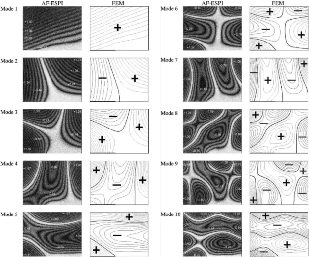
Fig. 3 First 10 mode shapes of the cracked rectangular plate with a = 20 mm obtained by AF-ESPI and nite element method (FEM).
map of the displacement eld. The plate is excited to resonance by a piezostack actuator (PI Company, 2£3 £ 20 mm) that is attached behind the specimen. To achieve the sinusoidal output, a digitally controlled function generator HP33120A (Hewlett–Packard Com-pany) connectedto a 4005 power ampli er (NF Corporation) is used. Numerical results of resonant frequencies and mode shapes are obtained by using the ABAQUS nite element package.6 A total
number of 1200 elements with eight-node two-dimensional shell elements (S8R5) are used in the analysis.This elementapproximates the Midlin-type element that acounts for rotary inertia effects and rst-order shear deformations through the thickness.
Table 1 shows the experimental and numerical results of the rst 10 resonant frequencies for cracked cantilever plates with different crack lengths (20, 35, and 50 mm). The results are quite consis-tent. Note that all of the experimental measured frequencies are lower than the numerical ones. The main reason is believed to be that the clamped condition of the cracked cantilever plate for the experimental setup is not ideally rigid. Furthermore, the errors for measuring the material propertiesand the thicknessof the plate may also in uence the calculated results for resonant frequencies.
The contours of the resonant mode shapes obtained from the -nite element calculation are plotted for comparison with the ex-perimental ones. Figures 3–5 show the rst 10 mode shapes of cracked cantilever plates for both experimental measurements and
AIAA JOURNAL, VOL. 39, NO. 12: TECHNICAL NOTES 2421
Fig. 4 First 10 mode shapes of the cracked rectangular plate with a = 30 mm obtained by AF-ESPI and FEM.
2422 AIAA JOURNAL, VOL. 39, NO. 12: TECHNICAL NOTES numerical simulations. The excellent quality of the interferometric
fringe patterns obtained from the AF-ESPI method is demonstrated. In Figs. 3–5, we indicate the phase of displacementin nite element results with aC or ¡ sign. The regions of the same sign have in-phase motion, and nodal lines (thick black lines) are also shown in Figs. 3–5. The brightestfringeson the experimentalresults represent the nodal lines of the vibrating cracked plate at resonant frequen-cies. The rest of the fringes are contours of constant displacement. It can be seen that the vibration mode shapes obtained experimen-tally agree very well with those obtained from the nite element method.
The related amplitude Ai; iD 1; 2; 3; : : : ; n; for the ith fringe
in the experimental results can be quantitatively calculated by the roots Riof J0.0 Ai/D 0. The rst 10 roots Rifor J0.Ri/D 0 are 2.4,
5.52, 8.65, 11.79, 14.93, 18.07, 21.21, 24.35, 27.49, and 30.63. The correspondent amplitude Ai of the out-of-plane displacement can
be evaluated by the following equation: Ai D
¸Ri
2¼.1C cosµ/ (3)
We use µD 10 deg for the experimental setup and ¸ D 632:8 nm; the related amplitudes for the rst 10 dark fringes are Ai; iD
1» 10,D 0.12, 0.28, 0.44, 0.6, 0.76, 0.92, 1.08, 1.24, 1.41, and 1.57 ¹m. The maximum value of the vibration displacement and related amplitudes of some fringes in the experimental results are indicated in Figs. 3–5. Note that the vibration displacements ob-tained in this study are in the order of a micrometer.
Because the crack will introduce a new free boundary of the can-tilever plate, the mode shape of a cracked plate is complicated and quite different from that of a plate without a crack. A complete dis-cussion of out-of-plane vibration mode shapes for different bound-ary conditions of isotropic plates without cracks was presented by Huang and Ma.7The vibrating mode shapes of the rst and the
sec-ond modes shown in Figs. 3–5 are pure bending and torsion modes, respectively.The mode shapes for long cracks (Figs. 4 and 5; aD 35 and 50 mm) are similar, but they are quite differentif comparedwith mode shapes for the short crack (Fig. 3; aD 20 mm). Note that the displacements along the crack surface for the rst 10 modes are all in-phase for the short crack and that the nodal lines will not pass the crack surface. However, the nodal lines of modes 7 and 9 for long cracks are terminated at the crack surface.
III. Conclusions
Investigation of the vibration problem by employing the ESPI method has the advantages of real-time and noncontact measure-ment, submicron sensitivity,digital image processing, and so on. In this Note, a self-arranged AF-ESPI optical setup with good fringe visibility and noise reduction was established to obtain the res-onant frequencies and corresponding mode shapes of cantilever cracked plates at the same time. Compared with the spectrum analy-sis method or modal analyanaly-sis method, AF-ESPI is more convenient in experimental measurement, and excellent quality of the inter-ferometric fringe patterns are obtained. Numerical calculations of resonant frequencies and mode shapes based on a nite element package are also performed, and good agreement is obtained in comparison with experimental measurements. The in uence of the crack length on the vibrationbehaviorof the cantilevercrackedplate is discussedin detail. Note that frequenciesobtainedexperimentally are typically lower than theoretical ones because one cannot get the perfectly rigid clamping condition.
Acknowledgment
The authors thank the National Science Council (NSC) of the Republic of China for supporting this research under Grant NSC 87-2218-E002-022.
References
1Rastogi, P. K., Holographic Interferometry, Springer-Verlag, Berlin, 1994.
2Butters, J. N., and Leendertz, J. A., “Speckle Pattern and Holographic Techniques in Engineering Metrology,” Optics Laser Technology, Vol. 3, No. 1, 1971, pp. 26–30.
3Wang, W. C., Hwang, C. H., and Lin, S. Y., “Vibration Measurement by the Time-Averaged Electronic Speckle Pattern Interferometry Methods,” Applied Optics, Vol. 35, No. 22, 1996, pp. 4502–4509.
4Ma, C. C., and Huang, C. H., “The Investigation of Three-Dimensional Vibration for Piezoelectric Rectangular Parallelepipeds Using the AF-ESPI Method,” IEEE Transactions on Ultrasonics, Ferroelectrics, and Frequency Control, Vol. 48, No. 1, 2001, pp. 142–153.
5Huang, C. H., and Ma, C. C., “Vibration Characteristics for Piezoelectric Cylinders Using Amplitude-FluctuationElectronic Speckle Pattern Interfer-ometry,” AIAA Journal, Vol. 36, No. 12, 1998, pp. 2262–2268.
6“ABAQUS User’s Manual,” Ver. 5.5, Hibbit, Karlsson, and Sorensen, Inc., Pawtucket, RI, 1995.
7Huang, C. H., and Ma, C. C., “Experimental Measurement of Mode Shapes and Frequencies for Vibration of Plates by Optical Interferometry Method,” Journal of Vibrationand Acoustics, Vol. 123, No. 2, 2001, pp. 276–
280.
A. M. Waas Associate Editor
Static and Dynamic Validations
of a Re ned Thin-Walled
Composite Beam Model
Zhanming Qin¤and Liviu Librescu† Virginia Polytechnic Institute and State University,
Blacksburg, Virginia 24061-0219 I. Introduction
T
HE increasingneed for weight saving and structural ef ciency of aerospace vehicles has prompted wide use of thin-walled beam structures.1 At the same time, due to the increasedimpor-tance of composite materials in the design of aerospace vehicles, the concept of anisotropic thin-walled beam model has reached special prominence in the last two decades.1;2However, in contrast
to the metallic structures, the composite structures exhibit signi -cant nonclassicaleffects such as transverseshear, warping restraint, three-dimensionalstrain effect,and contourwiseshearstiffnessvari-ations. Toward a reliable design, these effects should be accounted for and assessed even in the predesign process. In fact, in the past years, a number of analytical models of anisotropic thin-walled beams have been proposed and validated either numerically or in light of the experimental evidence.2 On the other hand, although
a re ned thin-walled beam theory originally developed by Song3
and Librescu and Song1 has been extensively used for the study,
among others, of dynamic response/structural feedback control3¡10
and static aeroelasticity,3;7;11;12no validationsof it againstthe
exper-imental, analytical, or numerical predictions obtained within other thin-walledbeam modelsare availablein literature.Within the frame of this re ned model, some effects such as the three-dimensional strain effect13;14and nonuniformityeffect of contourwiseshear
stiff-ness, that are also usually signi cant for the laminated composite beams2;13¡15and were not formerly accountedfor, are further
incor-porated, and the model hereby developed is investigatedagainst the available data from experiments, nite element method, and other analytical models.
II. Theory
A single-cell, closed cross section, ber-reinforced composite thin-walled beam is considered. The coordinate system that is
Received 3 January 2001; revision received 20 August 2001; accepted for publication 21 August 2001. Copyright c° 2001 by the American Institute of Aeronautics and Astronautics, Inc. All rights reserved. Copies of this paper may be made for personal or internal use, on condition that the copier pay the $10.00 per-copy fee to the Copyright Clearance Center, Inc., 222 Rose-wood Drive, Danvers, MA 01923; include the code 0001-1452/01 $10.00 in correspondence with the CCC.
¤Graduate Teaching Assistant, Department of Engineering Science and Mechanics. Student Member AIAA.