國
立
交
通
大
學
資訊工程系
碩
士
論
文
在嵌入式混合模式爪哇虛擬機器中
使用多重載入/儲存指令之實驗
Experiment on Using Load/Store Multiple Instruction
in Embedded Mixed-Mode JVM
研 究 生:黃俊諭
指導教授:鍾崇斌 教授
在嵌入式混合模式爪哇虛擬機器中
使用多重載入/儲存指令之實驗
Experiment on Using Load/Store Multiple Instruction
in Embedded Mixed-Mode JVM
研 究 生:黃俊諭 Student:Jun-Yu Huang
指導教授:鍾崇斌 Advisor:Chung-Ping Chung
國 立 交 通 大 學
資 訊 工 程 系
碩 士 論 文
A ThesisSubmitted to Department of Computer Science and Information Engineering College of Electrical Engineering and Computer Science
National Chiao Tung University in partial Fulfillment of the Requirements
for the Degree of Master
in
Computer Science and Information Engineering
August 2005
Hsinchu, Taiwan, Republic of China
在嵌入式混合模式爪哇虛擬機器中
使用多重載入/儲存指令之實驗
學生:黃俊諭
指導教授:鍾崇斌 博士
國立交通大學資訊工程學系碩士班
摘
要
在記憶體受限的嵌入式爪哇執行環境中為了達到加速,在直譯器之外
加入一個輕型的即時編譯器(JIT compiler)來動態編譯經常被執行的程式片
段是一種常見的設計。然而這種混合模式(mixed-mode)的爪哇虛擬機器於
執行過程中,會經常在直譯器與動態編譯產生的程式碼之間做切換,造成
動態產生的程式碼中,出現大量對區域變數(local variable)與運算元堆疊
(operand stack)的載入/儲存(Load/Store)指令,約佔所有動態產生程式碼的
三分之一。
在本篇研究中,便是針對此一現象設計優化動作,嘗試將這些載入/
儲存指令以多重載入/儲存(Load/Store Multiple)指令來取代,並且藉由調整
區域變數的順序與修改暫存器配置(register allocation)等方式,使得更多載
入/儲存指令能夠符合被取代的條件,以達到減少程式碼及增加執行速度的
目的。根據實驗結果顯示,在一個執行於 ARM7 的嵌入式混合模式爪哇虛
擬機器中使用多重載入/儲存指令,可使動態產生的程式碼平均加速可達
3.3%,程式碼減少達 6%。
Experiment on Using Load/Store Multiple Instruction
in Embedded Mixed-Mode JVM
Student: Jun-Yu Huang
Advisors: Dr. Chung-Ping Chung
Department of Computer Science and Information Engineering
National Chiao Tung University
ABSTRACT
Mixed-mode execution that combines an interpreter with a light-weight JIT
compiler is well suited to an embedded JVM that demands for speed
performance and has limited memory budget. However, the mode switch
between interpreter and JIT compiled code occurs frequently, and a great deal
of load/store instructions are generated by JIT compiler to synchronize the local
variable array and operand stack at each compiled code entry and exit point.
These load/store instructions that access to local variable array and operand
stack occupy about one-third of JIT compiled code.
In this research, the optimization to utilize Load-Store-Multiple instruction
to efficiently replace these load/store instructions is implemented for JIT
compiled code size reduction and speedup. In addition, the approaches of
adjusting the local variable placement and modifying register allocator to make
more load/store replaceable are also adopted. Experimental results show that an
average JIT compiled code speedup of 3.3% and code size reduction of 6% are
achieved.
誌謝
首先要感謝我的指導教授 鍾崇斌教授。在老師的諄諄教誨與細膩地引
導之下,本篇論文才得以順利完成,也使我更知道該如何自我檢視,發現
缺失。鍾老師卓越超群的組織與表達能力,亦是學生終生學習的目標。
在此也要感謝實驗室的另一位大家長─單智君老師。在研究的過程
中,單老師也同樣花費非常多的時間與精力來指導我,協助我克服了許多
困難。單老師在指導學生上的耐心與毅力,是大家有目共睹的。
感謝陪伴我走過這段時間的每一個人,包括我的家人、朋友、實驗室
的學長與同學們,經常在我感到失意挫折時給予鼓勵和建議。如果沒有你
們的支持協助,我不會如此順利地完成這篇論文。
在此向所有支持我、勉勵我的師長、同學、親友們,奉上我由衷的祝
福,謝謝你們。
黃俊諭
2005.8.26
Table of Contents
摘要
i
ABSTRACT
ii
誌謝
iii
Table of Contents
iv
List of Figures
vi
List of Tables
viii
Chapter 1 Introduction
1
1.1 Embedded Java Environment
1
1.2
Embedded Mixed-Mode Execution JVM
3
1.3 Load/Store Multiple Instruction
4
1.4 Research Motivation and Objectives
6
1.5 Thesis Organization
7
Chapter 2 Background
8
2.1 Java Technology
8
2.1.1 JVM Benefits
9
2.1.2 JVM Internals
9
2.1.3 JVM Implementation Alternatives
11
2.2 Overview of Our Embedded Mixed-Mode JVM
12
Chapter 3 Designs
15
3.1 How to use Load/Store Multiple in embedded mixed-mode JVM
15
3.1.1 Constraints of Replacing Load/Store by LDM/STM
15
3.1.2 Strategies to Make More Load/Store Replaceable
17
3.2 Design Overview
19
3.3 Local Variable Relocation
20
3.4 Modification of Register Allocator
25
3.5 Group load/store into LDM/STM
28
Chapter 4 Experiments
31
4.1 Experiment Environment
31
4.2 Benchmarks
31
4.3 Experiment Results
32
4.3.1 Effect on Execution Time
34
4.3.2 Effect on Code Size
36
Chapter 5 Conclusions
38
List of Figures
Figure 1-1. Java 2 Platform
2
Figure 1-2. Example of LDM/STM
4
Figure 1-3. Example of load/store and LDM/STM execution in ARM7 pipeline
5
Figure 1-4. Mode switch between interpreter and JIT compiled code
6
Figure 2-1. JVM Runtime Environment
9
Figure 2-2. Three Alternatives to Executing Java Programs
11
Figure 2-3. System Components and Their Interactions
12
Figure 2-4. KJITC Compiler Architecture
13
Figure 3-1. Example of Replaceable and Non-replaceable Load/Store
Instructions
16
Figure 3-2. Example of Replaceable and Non-replaceable Load/Store
Instructions
16
Figure 3-3. Example of Replaceable and Non-replaceable Load/Store
Instructions
17
Figure 3-4. Design Overview
19
Figure 3-5. An Example of Gathering Grouping Information
21
Figure 3-6. An Example of Transforming Grouping Information to Access
Graph
22
Figure 3-7. An Path Cover Obtained Largest-Weight-First Algorithm
23
Figure 3-8. A Dependence Graph of a Basic Block in JIT Compiled Code
25
Figure 3-9. An Example of Hint Generation
26
Figure 3-10. An Example of Grouping Load/Store into LDM/STM
30
Figure 4-1. JIT Compilation time Ratios of Configurations
35
Figure 4-2. The Speedup of JIT Compilation and Compiled Code Execution
Time of All Configurations
35
Figure 4-3. The JIT Compiled Code Size Ratio of All Configurations
37
Figure 5-1. Stall Cycle Reduction of Utilizing LDM/STM on 3-stage and
List of Tables
Table 1-1. J2ME Configurations
2
Table 4-1. Selected Tests of Embedded CaffeineMark 3.0
32
Table 4-2. Configurations of Different Optimization Combinations
33
Table 4-3. Execution Time Distribution Ratios of Benchmark Programs
34
Table 4-4. JVM Code Size of Different Configurations
36
Chapter 1
Introduction
In this chapter, we introduce terms in the title and the concept of our research. First, we give an overview of the current status of the Java technology in embedded environment. Second, we explain the meaning of mixed-mode, which actually combines interpretation and just-in-time (JIT) compilation. Third, we introduce the load/store multiple instruction that is supported by embedded architecture, such as the ARM and XScale processors. After the introduction comes our research motivation and objectives. Finally, organization of this thesis is provided.
1.1 Embedded Java Environment
Java technology is developed by Sun in 1991 and rapidly becomes popular in all application fields, such as desktop PCs, powerful large-scale server, or even in small portable devices. In order to meet the demands of different application fields with different characteristics, Sun in 1999 has grouped Java technologies into the Java 2 platform [1], which consists of three editions as in Figure 1-1, and each of which is specialized for a specific area:
‧ Java 2 Enterprise Edition (J2EE) - targeted at scalable, transactional, and database-centered enterprise applications with an emphasis on server-side development.
Figure 1-1. Java 2 Platform (extracted from Sun)
‧ Java 2 Standard Edition (J2SE) - targeted at conventional desktop applications. ‧ Java 2 Micro Edition (J2ME) - targeted at embedded and consumer devices,
such as wireless handhelds, PDAs, TV set-top boxes, and other devices that lack the resources to support full J2SE implementation.
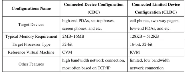
To address the diversity of embedded devices with different network connectivity and memory footprint, J2ME specifies two configurations: Connected Limited Device Configuration (CLDC) and Connected Device Configuration (CDC). Each configuration targets at different types of devices and therefore provides different class libraries and APIs. Table 1-1 shows an overview of the differences of the two configurations.
Table 1-1. J2ME Configurations
Configurations Name Connected Device Configuration (CDC)
Connected Limited Device Configuration (CLDC)
Target Devices high-end PDAs, set-top boxes, screen phones, and etc.
cell phones, two-way pagers, low-end PDAs, and etc. Typical Memory Requirement 2MB~16MB 128KB ~ 512KB
Target Processor Type 32-bit 16-bit, 32-bit Reference Virtual Machine CVM KVM
Other Features high bandwidth network connection, most often based on TCP/IP
limited, low bandwidth network connection
1.2 Embedded Mixed-Mode Execution JVM
Although the JVM can be easily realized by an interpreter, its slow performance is always a great issue in performance-aware system. In order to overcome this problem, some compilation technologies were applied for speedup. Ahead-of-time (AOT) compilers [2] allow offline compilation to translate bytecode into machine code; hence no run-time compilation overhead is caused but result in application code size expansion about five times. Conventional JIT compilers translate bytecode into machine code on the fly, and apply more optimization techniques for better performance with the cost of VM code size increase and run-time compilation overhead. However, these approaches might not be adoptable in some embedded JVM because of the memory constraint.
The approach of mixed-mode execution in [3][4] relies an interpreter to execute bytecode for some parts of the program, and also executes compiled code that dynamically produced by a JIT compiler for the remaining parts. The line between a conventional JIT compiler and a JIT compiler that supports mixed-mode execution is, in actuality, unclear. However, the principles of mixed-mode execution can be clarified as follows.
‧ Performance-critical parts of the program are compiled by a JIT compiler, and then natively executed.
‧ Non-performance-critical parts of the program are interpreted by an interpreter. ‧ Close interactions between the JIT compiler and the interpreter is necessary.
By reusing the interpreter-based JVM as its infrastructure, the JIT compiler of a mixed-mode JVM can be implemented with very small code size (about several tens of kilo-bytes). Therefore, while designing an embedded JVM with the demand of speed performance, a mixed-mode JVM seems to be promising. And the
combination of an interpreter-based JVM and a light-weighted JIT compiler builds up an embedded mixed-mode JVM.
1.3 Load/Store Multiple Instruction
Some embedded architecture, such as the ARM processors support load multiple (LDM) or store multiple (STM) instructions to perform multiple register data transfers from/to memory. The formats of LDM/STM instruction are:
LDM baseRegister, {bitVector} STM baseRegister, {bitVector}
The operands of LDM/STM instruction consist of a base register that holds a memory address, called the base address, and a bit-vector that denotes a subset (possibly all) of the general-purpose registers. These registers indicated by bit-vector would be loaded from or stored to a contiguous block of memory word starting from base address.
simple example of load/store multiple instruction is showed in Figure 1-2. This
A
example illustrates a common feature of these instructions: the lowest register is transferred from/to the lowest memory address and the other registers are transferred in order of register number from/to consecutive word addresses above the first address.
r5
r7
r2
Memoryr0
Address 0x08 0x0C 0x04 0x00 0x10 0x08 0x0C 0x04 0x00 0x10 STMIA r0, {r2, r5, r7} or 0000000010100100 0000 STMIA r0 r15 r2r7 r5 Figure 1-2. Example of LDM/STMThe benefit of utilizing load/store multiple to replace several load/store instr
lacing n load/store instructions by single load/store
‧ azard: In ARM7, a
simple example of executing load/store and the equivalent LDM/STM uctions are listed below:
‧ Reducing code size: if rep
multiple instruction, code size can be reduced (n-1) word.
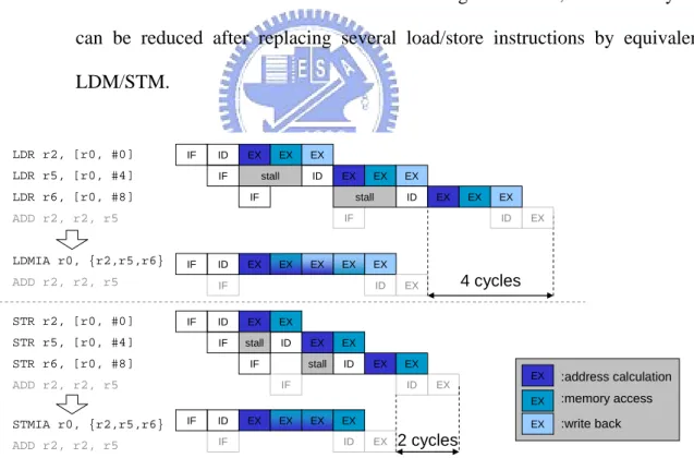
Reducing pipeline stall cycles caused by structure h
3-stage pipeline RISC processor, both load and store instruction occupy execution stage more then one cycle: Store takes two cycles for address calculation and memory access; Load takes one cycle more then store because the extra work of writing data into register also takes one cycle. Therefore, Processor must stall one cycle for each store and stall two cycles for each load because of the structure hazard in execution stage. However, these stall cycles can be reduced after replacing several load/store instructions by equivalent LDM/STM.
A
instructions by ARM7 pipeline is showed in Figure 1-3. During the execution of
IF ID EX IF ID EX IF ID IF ID IF ID EX EX EX IF stall ID EX EX EX LDR r2, [r0, #0] LDR r5, [r0, #4] ADD r2, r2, r5 IF ID EX EX LDMIA r0, {r2, r5} ADD r2, r5, r5 EX EX IF ID EX EX IF stall ID EX EX STR r2, [r0, #0] STR r5, [r0, #4] STR r6, [r0, #8] ADD r2, r2, r5 IF ID EX STMIA r0, {r2,r5,r6} ADD r2, r2, r5 EX EX EX LDR r2, [r0, #0] LDR r5, [r0, #4] LDR r6, [r0, #8] ADD r2, r2, r5 LDMIA r0, {r2,r5,r6} ADD r2, r2, r5 IF stall ID EX EX EX EX EX EX EX :address calculation :memory access :write back IF stall ID EX EX EX EX 4 cycles 2 cycles
LDM/STM, the address calculation, memory access and write back of different memory accesses are parallelized and hence the total execution cycles are reduced. To be more precise, replacing n load instructions by one equivalent LDM can result in 2(n-1) stall cycles reduction and replacing n store instructions by STM can result in (n-1) stall cycles reduction.
1.4 Research Motivation and Objectives
d some complex bytecodes that invo
Inspection load/store
instr
Because of very limited memory budget an
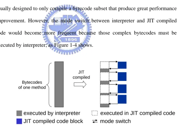
lve complicated operations that suit for interpreter handling (such as object creation, method invocation), the JIT compiler of embedded mixed-mode JVM is usually designed to only compile a bytecode subset that produce great performance improvement. However, the mode switch between interpreter and JIT compiled code would become more frequent because those complex bytecodes must be executed by interpreter; as Figure 1-4 shows.
JIT compiled Bytecodes
of one method
█executed by interpreter executed in JIT compiled code
█JIT compiled code block mode switch
Figure 1-4. Mode switch between interpreter and JIT compiled code
of the JIT compiled code reveals that, a great deal of
uctions is generated by JIT compiler to synchronize the local variable array and operand stack at each compiled code entry and exit point. In compiled code generated by KJITC [7], a JIT compiler of an embedded mixed-mode JVM
developed by our research group, these load/store instructions occupy 39% of JIT compiled code and 30% of JIT compiled code execution trace.
Motivated by this fact, our objective is to make use of the benefits of repla
eveloped by [7]. It co
1.5 Thesis Organization
is organized as follows: Chapter 2 provides more detai
cing the load/store of local variable array and operand stack by load/store multiple instructions in embedded Java JIT compiled code to achieve speed performance improvement and JIT compiled code size reduction.
In addition, the embedded mixed-mode JVM we choose is d
mbines an interpreter-based VM, which is modified form Sun’s CLDC KVM 1.0.4, and a light-weighted JIT compiler, named KJITC, to generate ARM instructions.
The rest of the thesis
led background knowledge on JVM internals and an overview of our embedded mixed-mode JVM. Chapter 3 discusses about how to utilize LDM/STM in JIT compiled code and describes optimizations for utilizing LDM/STM. Chapter 4 gives the experiment results. The last chapter summarizes the work.
Chapter 2
Background
This chapter provides more background details on JVM internals and an overview of our embedded mixed-mode JVM. Readers who are already familiar with the two topics can skim over them.
2.1 Java Technology
Although generally used to refer to a computer language, Java is rather a complete architecture in reality. It consists of four components [8].
‧ Java programming language ‧ Java class file format
‧ Java Application Programming Interface (Java API) ‧ Java Virtual Machine (JVM)
A Java program which is written in Java programming language can be compiled into Java class files by Java source compiler. JVM is a virtual stack machine that execute Java class file. The Java program can access predefined libraries or system resources (such as I/O, for example) by calling methods in the classes that implement the Java API. During program execution, JVM loads and executes user-written class files as well as these system classes that Java API defines.
2.1.1 JVM Benefits
Java Virtual Machine is the key component among the all. It is responsible for the well-known advantages of Java comparing to traditional native execution system. Those advantages include:
‧ Cross-Platform Portability
‧ Security of the Execution Environment ‧ Small Size of the Compiled Code
2.1.2 JVM Internals
A JVM implementation must provide the functionality of a real processor and also conform to the JVM specification [9]. The specification defines a homogeneous run-time environment, as Figure 2-1 illustrates, by providing a detailed description of the following items:
Figure 2-1. JVM Runtime Environment (extracted from [7])
‧ Instruction Set (Java Bytecode) ‧ Register Set
‧ Java Stack
‧ Execution Environment ‧ Constant Pool
‧ Method Area ‧ Java Heap
‧ Object Management and Garbage Collection
Since the JVM is a stack-based architecture, the registers of its register set are not used for storing operands or passing arguments as in most register-based machine. They only hold the state of the JVM and are updated after every bytecode instruction is executed, such as program counter.
Before the bytecode instruction is executed, operands must be pushed onto the operand stack, which resides in method frame pushed in Java stack. An executing instruction pops its operands from the operand stack and then places results on the operand stack when it completes.
The Java stack is similar to the stack of conventional language, such as C; it contains method frames and is manipulated to realize method invocation/return.
The JVM maintains a special table for each class, known as a constant pool. The constant pool contains string literals, class names, field names and other constant data objects that are referred to by the class structure. These constants do not change, and are created at compile-time.
The method area is equivalent to the compiled code areas in the run-time environment used by other programming language. It contains bytecode instructions that are associated with the methods and the symbol table needed for dynamic linkage.
The Java heap is the dynamic memory of JVM, and it usually contains a collection of objects. When an object is created with the “new” bytecode instruction, a reference to that object is returned. This reference can be used subsequently, or stored in the current frame. An object is live in Java heap until there are no references to it in any frame or in the field of any visible object. When
there are no such references, an object becomes garbage, and a garbage collector will reclaim its resources.
2.1.3 JVM Implementation Alternatives
The JVM is not restricted to software interpreter implementation. In fact, there are three common approaches, as depicted in Figure 2-2, to implement the JVM.
The first approach is using interpreter to execute bytecode. It makes the VM porting easier, but the execution speed is low. The second approach is to replace interpreter with a bytecode compiler. The bytecode compiler is used to translate bytecode into native machine code. While ahead-of-time (AOT) compilers performs offline compilation, just-in-time (JIT) compilers performs on-the-fly compilation at run-time. Both of them have pros and cons, but JIT compilers seem to be more popular. The third approach is to implement the JVM directly on silicon. For example, picoJava is a Java processor that supports bytecode execution
As discussed in Section 1.2, an interpreter can still coexist and cooperate with a JIT compiler in the JVM. Recently, a mixed software/hardware approach also arises; ARM has introduced its own Java instruction extension - Jazelle [11]. A subset of bytecode instructions can be directly executed when the ARM processor is operated in Java mode, and the remaining bytecode instructions are still handled in software.
2.2 Overview of Our Embedded Mixed-Mode JVM
In our mixed-mode embedded JVM, there are four main components. Their interactions can be simply illustrated in Figure 2-3.
Now we respectively describe each component as follows.
Figure 2-3. System Components and Their Interactions (extracted from [7])
‧ Interpreter-based JVM (KVM)
The interpreter-based JVM provides a JVM infrastructure that performs exception handling, garbage collection, synchronization and etc. For mixed-mode execution, the interpreter is also responsible for invoking the hot spot detector and switching to/form compiled code in addition to interpretation of those bytecode that have not been compiled or will not be compiled.
‧ Hot Spot Detector
Due to the tight memory constraints, only valuable parts of the input program are selected for JIT compilation. By the 80/20 rule, over eighty percent of execution time is spent in less than twenty percent of source code in a program. Apparently, the responsibility of the hot spot detector is to discover these performance-critical twenty percent of source code and then invoke JIT compiler for hot spot compilation.
The basic unit of hot spot detection is a method. When a method is invoked frequently or contains at least one loop that iterate for many times, it is regarded as a hot spot an invoke KJITC to compile it. In our implementation, the threshold values of invocation count and iteration count must be set statically. Currently the values are both chosen to be 40, which are based on our evaluation results.
‧ JIT Compiler (KJITC)
The JIT compiler is further divided into the IR (Intermediate Representation) generator and the native code generator. The IR generator is mainly responsible for translating Java bytecode into semantically equivalent three-address IR. And then the code generator translates IR into targeted native code for later execution. A simple illustration is given in Figure 2-4. The design of the optimizations in KJITC
IR Generator
Function:
translation of Java bytecode into semantically equivalent 3-address IR
Optimizations:
1. rule-based null pointer check elimination
2. strength reduction
Native Code Generator
Function:
1. register allocation/assignment 2. instruction selection/ generation
Java Bytecode 3-address IR Native Code (eg. ARM) Optimizations:
1. instruction folding for stack operations
2. constant propagation
was described in [7] and we skip those details here. ‧ Compiled Code Buffer
The compiled code buffer holds all compiled native code. During native exec
addition to the four components, the switching mechanism between the inter
ution, the machine program counter (PC) points to native code that resides in the buffer. In our current implementation, the compiled code buffer is allocated statically, and its size is also predetermined.
In
preter and the compiled native code is also described here. Similar to a function call, the switch from the interpreter to the compiled native code involves spilling registers into memory and then transferring execution by a branch. The case of the switch from the compiled native code to the interpreter involves more operations. It has to restore registers from memory, to transfer execution by a branch, and to update Java PC (program counter) and Java SP (stack pointer).
Chapter 3
Designs
In this chapter, we discuss about how to utilize LDM/STM in JIT compiled code and describe optimizations for utilizing LDM/STM. Section 3.1 will discuss about the constraints of replacing load/store by LDM/STM and the strategies to deal with them, Section 3.2 will introduce the overview of my designs, and section 3.2 to 3.4 will show the design details.
3.1 How to use Load/Store Multiple in embedded mixed-mode
JVM
As we mentioned in Section 1.4, the load/store instructions that access to
local variable array and operand stack occupy a great portion of JIT compiled
code. However, not all the load/store instructions can be replaced by load/store multiple instructions but within constraints. In this Section, we will discuss the constraints and the strategies to increase the replaceable load/store instructions.
3.1.1 Constraints of Replacing Load/Store by LDM/STM
The major constraints of replacing these load/store instructions by load/store multiple are listed below:1. Accessed memory locations are contiguous
The load/store multiple are restricted to access consecutive memory words, and hence the load/store instructions that access to non-contiguous address can not
replace by LDM/STM. As Figure 3-1 (a) illustrates, only the first two loads that access to consecutive memory words are replaceable, but if the access address of the third load is adjusted to contiguous one as Figure 3-1 (b) show, all of them can be replaced by LDM.
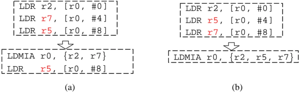
2. The DST/SRC register numbers and accessed memory addresses are in the same order
During the execution of LDM/STM, registers are transferred in order of register number from/to consecutive word addresses. If the DST/SRC register numbers and accessed memory addresses of load/store instructions are not in the same order, replacing them by LDM/STM will cause different result in register/memory from the original code sequence. As Figure 3-2 (a) shows, only the first two load instructions satisfy the constraint and can be replaced by equivalent LDM. After adjusting the destination register numbers of the last two load instructions as Figure 3-2 (b), all of them become replaceable.
(a) (b) LDR r2, [r0, #0] LDR r5, [r0, #4] LDR r7, [r0, #12] LDMIA r0, {r2, r5} LDR r7, [r0, #12] LDR r2, [r0, #0] LDR r5, [r0, #4] LDR r7, [r0, #8] LDMIA r0, {r2, r5, r7} LDMIA r0, {r2, r5, r7}
Figure 3-1. Example of Replaceable and Non-replaceable Load/Store Instructions
LDR r2, [r0, #0] LDR LDR r2, [r0, #0] LDR r7, [r r5, [r 0, #4] LDR r5, r7, [r0, #4] LDR [r0, #8] LDMIA r0, {r2, r5, r7} 0, #8] LDMIA r0, {r2, r7} LDR r5, [r0, #8] (a) (b)
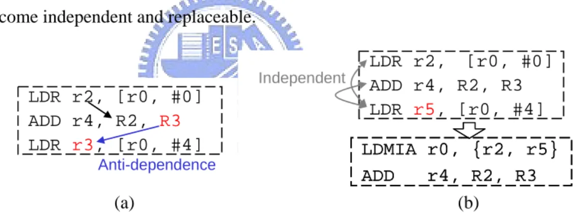
3. Load/store instructions only can be grouped together without affecting dependences
The load/store instructions to be replaced by LDM/STM are not necessary to be adjacent to each other in a code sequence, but have to be independent to each other. If there are dependences between load/store instructions, replacing them by LDM/STM will affect dependences and result in error. As Figure 3-3 (a) shows, the two load instructions are dependent because of the true dependence between the first and the second instruction and the anti-dependence between the second instruction and the third instruction. Therefore these load instructions are not replaceable. But if the register numbers of the third instruction is adjusted to resolve the anti-dependence as Figure 3-3 (b), the two load instructions will become independent and replaceable.
3.1.2 Strategies to Make More Load/Store Replaceable
.1.1, the respe
1. M king
ous, since the oper
Basing on the three major constraints summarized in Section 3 ctive strategies to make more load/store replaceable are listed below:
a the access locations of groupable load/store contiguous The accesses to operand stack are almost always contigu
ations to access operand stack are simply push or pop rather then random
(a) (b) LDR r2, [r0, #0] ADD r4, R2, R3 r3, [r0, #4] LDR Anti-dependence LDMIA r0, {r2, r5} ADD r4, R2, R3 LDMIA r0, {r2, r5} ADD r4, R2, R3 LDR r2, [r0, #0] ADD r4, R2, R3 LDR r5, [r0, #4] Independent
accesses. The local variable accesses are more likely to be random accesses, but it is possible to adjust or permute the local variable array for each method to make more load/store instructions access to contiguous address and become replaceable. In fact, there are already researches [12][13] about adjusting variable locations by add phases into C/C++ compiler to maximize the benefit of utilizing LDM/STM, and it is also possible to apply them to Java method at bytecode level with little modification.
2. Making the order of register numbers right
guide-line: allocating lager register num
the register number constraint of utilizing is LDM/STM was also discu
This can be realized by following a simple
ber for lager memory address access. Since most RISC instructions are orthogonal and free to use any one of general purpose register, the register numbers of RISC instructions usually can be renamed/relabeled to obey the guideline without affecting correctness and/or code quality. Moreover, the register allocator might be modified to be aware of this guide-line without conflicting with the original allocation policy, because a simple register allocator for RISC machine usually only decide the range of variables reside in registers, and there is flexibility on which register number to allocate. We prefer to modify the register allocator to follow the guideline, since the register renaming might take an extra pass in JIT compilation.
In [13],
ssed and dealt with it by inserting extra instructions to swap register content. However, the extra instructions inserted will decrease the benefit of utilizing LDM/STM and this approach is even harder to implement when adjusting more then two register numbers at a time.
3. A oiding the name dependences between load/store and other instructions
s of instr
3.2 Design Overview
in components in my design: local variable relocation, mod
The objective of local variable relocation is to make more potentially ructions access to continous addresses and maxisize the bene
v
Name dependences can be avoided by adjusting register number uctions. This is also can be realized by applying register renaming or modifying the register allocator to be aware of it. Because of the same reason we mentioned earlier, we prefer to modify the register allocator to avoid name dependences.
There are three ma
ification of register allocation and grouping load/store into LDM/STM as illustrated in Figure 3-4.
groupable load/store inst
fit of utilizing LDM/STM. It is performed offline since solving it is a very
Run-time KJIT compilation Code gen IR gen register allocation ...
JIT compiled code Java method
(modified or un-modified)
Java method
Offline preprocess
for every compilable method
Modified Java method Local Variable
Relocation
Grouped Load/Store Info of each basic block Offline Profiling Info
(execution count of each basic block) 1 Modified Java method Local Variable Relocation Grouped Load/Store Info of each basic block Offline Profiling Info
(execution count of each basic block)
1
Register Allocation 2 3 Group load/store into
LDM/STM Group load/store into
LDM/STM
Grouping scope: Intra basic block 3
Making the order of register numbers right
2
Making the access location continuous
1
Avoiding the name dependences
JIT compilation
Register Allocation Group load/store into
LDM/STM Group load/store into
LDM/STM
time-consumed and memory-consumed process even by heuristic algorithm. After the local variable relocation decision comes out, relocation is simply done by rewriting the bytecodes that access to local variables. For example, if local variable one is decide to be relocated to local variable two, then the bytecodes such as ILOAD_1, IINC 1 2, and ISTORE_1 will be rewritten to ILOAD_2, IINC 2 2, and ISTORE_2. Therefore, the modified Java method is still correctly executable and those changes almost bring no effect on code size of program and the speed of interpretation.
The register allocation is performed during the code generation of JIT compilation. In my design, it is modified to make the order of register numbers right
d here to find out replaceable load/store instructions within basic bloc
3.3
Relocation
le relocation is to make the access location of adjusting the locations of local variables for each
and to avoid name dependences for making more load/store instruction replaceable.
After the register allocation and load/store instructions are generated, an extra pass is adde
ks and group them into LDM/STM.
The detail algorithms of each one of the three designs will be describe in the following sections.
Local Variable
The key idea of local variab groupable load/store continuous by
java method. The problem formulation is: given compiled instructions of each basic block with load/store of a method and the execution count of each basic block, obtain a memory layout of the local variables of the method that maximizes the benefit of using load/store multiple instructions. The benefit of utilizing
LDM/STM can be either code size reduction or stall cycle reduction as we discussed in Section 1.3.
There are three phases to accomplish the local variable relocation: gathering grouping information, transforming grouping information to access graph and decid
e are the JIT compiled instructions of each basic block of a unt of each basic block obtained by offline profi
ping are inde
instructions to cons
ing the layout of local variable. The actions of each phase are described in following paragraphs.
‧ Gathering grouping information Inputs of this phas
java method and the execution co
ling. Output is the grouping information consists of the load/store instruction groupings, the type and the execution count of each instruction grouping.
The instruction grouping consists of multiple load or multiple store instructions within a basic block. The instructions in the same grou
pendent to each other and access to different local variables. In addition, each load/store instruction belongs to one grouping at most. Note that the instruction of a grouping is not necessary to access to contiguous addresses here.
To find out the instruction groupings, we perform dependence check on instructions of each basic block and scan through the load/store
truct instruction groupings in greedy fashion. A simple example of gathering grouping information of a method is illustrated is Figure 3-5.
Access Grouping Info. of a method
… Load r1, r0, #b Load r2, r0, #c Load r3, r0, #d … Store r5, r0, #a Store r6, r0, #c Store r7, r0, #e …
JIT compiled code of each basic block
in a method … 2 (LD) 1 (ST) 2 (LD) T(G) ( LD/ST) … a,b a,c,e b,c,d Grouping G 100
a-c, c-e, a-e
150 a-b … 100 F(G) (execution count) … b-c, c-d, b-d Grouping pairs … 2 (LD) 1 (ST) 2 (LD) T(G) ( LD/ST) … a,b a,c,e b,c,d Grouping G 100
a-c, c-e, a-e
150 a-b … 100 F(G) (execution count) … b-c, c-d, b-d Grouping pairs … Load r7, r0, #a Load r8, r0, #b … ...
For ease of conduct the weighting formula to calculate benefit later, we define some
consists of load/store instructions:
‧
‧ T ing grouping information to access graph
s transformed to an access grap
ction = Sum(F(Gn) × T(Gn)) , where Gn containing both
‧ eduction = number of grouping that contain both vi and vj
ph is show
term for instruction grouping here: Definitions for an instruction group G
‧ F(G) = execution count of G (obtained by offline profiling) 2 if G consists of load (stall cycle reduced by replacing
T(G) =
ransform
In this phase, the grouping information gathered i
h. The access graph is a weighted graph; each node v of graph corresponds to a unique local variable; an edge<vi, vj> denotes the instructions access to vi and the
instructions access to vj fall in one or more common instruction group; the weight
of edge<vi, vj> is the benefit of vi and vj group together in a method. The benefit
can be either one below: ‧ Stall cycles redu
vi and vj
Code size r
A simple example of transforming grouping information to access gra ed in Figure 3-6.
1 if G consists of store (stall cycle reduced by replacing one pair of store) one pair of load)
300 a-b , b 2(LD) 150 a 400 400 1(ST) c-d, d-e, c-e c, d, e 200 100 2(LD) b-c, c-d, b-d b, c, d 100 100 1(ST)
a-c, c-e, a-e a, c, e
Grouping group pairs T(G) F(G) F(G) × T(G)
300 a-b , b 2(LD) 150 a 400 400 1(ST) c-d, d-e, c-e c, d, e 200 100 2(LD) b-c, c-d, b-d b, c, d 100 100 1(ST)
a-c, c-e, a-e a, c, e
Grouping group pairs T(G) F(G) F(G) × T(G)
a b c d e 300,1 200,1 100,1 400,1 100,1 500,2 600,2 200,1 Access Grouping Info. of a method transform to
access graph
Weight: stall cycles reduction, code size reduction
‧ Deciding the layout of local variable
l variables can be mapped to a path cover in th
-6. The path cover obtained by “Lar
In fact, any memory layout of loca
e graph, and finding the optimal memory layout is equivalent to finding the path cover with maximum weight. The problem of finding the path cover with maximum weight is called maximum weighted path cover problem (MWPC), and it has been proved to be NP-complete. Therefore, a heuristic algorithm called “Largest Weight First” is used to solve it. The algorithm is described below.
A simple example is illustrated in Figure 3
gest Weight First” in this example is “a-b-d-c-e”, which is also the optimal path cover in this graph. According this path cover, the memory layout local variables will be changed from “a-b-c-d-e” to “a-b-d-c-e”.
Step 1: Initialize the path cover P = { };
aph according to their weights (in
Step 3: P e largest weight and remove it from E.
Step 4 nd 3 until E is empty
Figu rithm
Step 2: Sort the edges of the access gr
descending order) into set E; ick up the edge e in E with th
If adding the edge e to P (i) does not form a cycle in P , and (ii) does not increase the degree of any node in P to more than 2, then it is included in P .
Repeat Steps 2 a
a
re 3-7.An Path Cover Obtained Largest-Weight-First Algo
b c d e 300,1 200,1 100,1 400,1 100,1 500,2 600,2 200,1
According to the JVM specification [9], some local variables can not be relocated, such as “this pointer” at local variable 0 or parameters, which must be placed in consecutive addresses start from local variable 0 or after “this pointer”. To deal with that, the initialization step in the “Largest Weight First” algorithm must be modified: while deciding the layout of local variables, these variables that can not be relocated are connected into a path according to their predetermined placement sequence and we put it in the path cover P at the step one. The rest of the algorithm is remained to build up the path cover.
The process of local variable relocation is also influenced by whether the register allocator of the JIT compiler is designed to allocate right register numbers and to eliminate the name dependences for consecutive variable accesses. If the register allocator will try to eliminate the name dependences between the consecutive variable accesses and other instructions, it is assumed the all the name dependences are removed and only the true dependences remain during the instruction group construction in the first phase. If results of the register allocation are independent to the locations of variables, we use the directed edge to represent the register number order between grouped local variable access instructions during the access graph construction in phase two. In addition, the weight calculation is also slightly modified to takes the register number constraint into account.
3.4 Modification of Register Allocator
The goal of modifying register allocator is to make more load/store instructions replaceable by making the order of register numbers right and avoiding name-dependences to. We use a simple example in Figure 3-8 to explain how to achieve this goal.
A dependence graph of a basic block in JIT compiled code is showed in Figure 3-8. These instructions can be divided into two groups: the consecutive address access instructions and the other instructions, as the dotted lines separated. The consecutive address accesses are grouping candidates that might be replaced by LDM/STM later.
To make the order of register numbers right, we can simply allocating ascending register numbers for consecutive address accesses that sorted in ascending order.
However, some dependences between the consecutive address accesses and other instructions still make some loads/stores non-replaceable. For example, the name dependence between “ADD” and “LD mem[n+1]” in Figure3-8 making the “LD mem[n]” and “LD mem[n+1]” dependent and non-groupable. To avoid that,
Inst. access to n+2 Inst. access to n+1 Inst. access to n Inst. access to n+2 Inst. access to n+1 Inst. access to n < < Consecutive address accesses (grouping candidates) other instructions Ri Rj Rk
Use other registers as destination register rather than Ri, Rj, Rk
LD mem[n] LD mem[n+1] LD mem[n+2]
ADD LD mem[n+4] ADD ADD Register: true dependence name dependence true dependence name dependence
we can allocate other registers for other instructions as destination registers rather then those allocated for consecutive address accesses.
The scope of register allocation in the JIT compiler of our embedded mixed-mode JVM is extended basic block, which is code sequence with a unique entry point and possibly many exits points. The original register is two-pass register tracking, similar to the register allocator in [14]. The first pass is live-ness analysis; the second pass is sequentially allocating registers and generating instructions for each IR.
Modified register allocator is still a 2-pass scheme. The first pass is modified to find out consecutive address accesses within basic block along with the live-ness analysis and generate hints (preserved register and address pairs) for them. The register allocation in second pass would be guided by these hints later.
A simple example of hint generation in first pass is illustrated in Figure 3-9. First, we scan through the IR of EBB and log the read/written addresses for each basic block. If there are consecutive addresses to be read/written within a basic block, we preserve ascending register numbers for loading/storing these memory addresses as hints to register allocator.
:Top of stack R5 R4 R3 R2 R1 R/W R/W R/W R R R R/W 5 R R/W R R/W W R R 3 4 W R R5 R4 W 8 7 … 2 1 0 R5 R4 R3 R2 R1 R/W R/W R/W R R R R/W 5 R R/W R R/W W R R 3 4 W R R5 R4 W 8 7 … 2 1 0 MOV LV[7],LV[3] MOV LV[8],LV[1] ADD LV[7],LV[7],LV[8] MOV LV[8],LV[4] ADD LV[7],LV[7],LV[8] ADD LV[5],LV[5],#1 ILOAD_3 ILOAD_1 IADD ILOAD_4 IADD INC 5 1 Address:
Local variable array Operand Stack
Bytecode IR
Preserved register for Load: Preserved register for Store: Access log: Hints for register allocator
The register allocation in second pass is also modified to follow the hint. The modified register allocation policy described as below.
The modified allocation policy follows the hints in conservative way: if the preserved register is occupied at step 1, we do not spill that register but try to find another available one to allocate. The reason of the conservatism is that the overhead of the extra register spill is usually greater then the benefits of replacing more load/store by LDM/STM. Although the conservative policy might tend to failed to follow hints at step 1 (because the preserved register for m is occupied) when register pressure is high, but we found that the register pressure is rarely get high in JIT compiled code since the size of EBB is usually small.
When spilling register, the register with the lowest spill cost, which represents the estimated number of extra instructions to be generated because of the register spilling, is chosen to spill in the original policy. The modified policy still use the original metric to choose the register, but if both non-preserved and preserved register are chosen, spill the non-preserved first to avoid the name dependences
Allocation policy
When allocating register for memory address m:
Step 1: Try to allocate register according to hint
If there is an available preserved register for m, use it and release the original register allocated for m then exit; otherwise go to Step 2
Step 2: Use the original allocation policy to allocate register
But if both non-preserved and preserved registers are free, use the non-preserved first
occur on preserved registers.
Note that, the modified register allocation policy does not increase the amount of occupied register at each allocation point, since the original register number allocated will be released while allocating another register number of variable in step one. In addition, the modified spill policy also does not seem to cause more load/store instructions in JIT compiled code, since the spill cost of choused register is always the same as one that choused by original spill policy.
3.5 Group load/store into LDM/STM
The goal of this design is to efficiently replace the load/store instructions within basic block by LDM/STM whenever possible. Since the code scheduling crossing basic block, such as trace scheduling, is usually too expansive to implement in an embedded JIT compiler, the load/store grouping scope is decided to be basic block.
There are three phases to group load/store into LDM/STM: dependence checking, load/store grouping, and instruction regeneration. The actions of each phase are described in following paragraphs.
‧ Dependence checking
After generating the first load/store in a basic block, we start to build the data dependence graph for later generated instructions. After the instructions of a basic block are all generated, if more than one load/store instruction is generated, go to the next phase and exit if otherwise, since it is not necessary to try to replace single load/store by LDM/STM.
‧ Load/store grouping
The algorithm of load/store grouping is listed below.
Step 1 (Sort load/store): put load/store instructions into two different queues and sort
by accessed address respectively
Step 2 (Find a load/store group): scan through the sorted load/store instruction queues
and get a load/store group that satisfies all constraints; if no such group is found in queue, go to the next phase
Step 3 (Replace the load/store group by LDM/STM): allocate a register as base
address register and insert a instruction (if necessary) to set base address for each group; replace the grouped load/store instructions by load/store multiple and annotate it in the dependence graph, go to step 2
‧ Instruction regeneration
If any load/store replacement occurs, instructions will be regenerated according to the original instruction sequence and the dependence graph. While regenerating the instruction I, if there are instructions that I depends on and un-regenerated, we recursively regenerate those instructions first and then generate
An example of grouping load/store into LDM/STM is illustrated in Figure 3-10 to help reader to realize the three phases.
The time complexities of the second and the third phase: load/store grouping and instruction regeneration are both linear to the instruction count of a basic block and the same as the most optimizations in JIT compiler. The time complexity of dependence check is O(n2) where n is the instruction count of a basic block. However, the size of basic block is smaller then seven instructions in most cases; therefore the time spent on dependence seems to be affordable.
1:LV3 r1 2:LV1 r2 4:LV4 r2 6:LV5 r3 1:LV3 r1 2:LV1 r2 4:LV4 r2 6:LV5 r3 1:LV3 r1 2:LV1 r2 4:LV4 r2 6:LV5 r3 sort load/store by accessed address 1:LV3 r1 2:LV1 r2 4:LV4 r2 6:LV5 r3 sort load/store by accessed address
Load Instruction Queue
2 LV1 1 LV3 6 LV5 3 3 4 LV4 5 7 dependence Dependence Graph 1 ADD r1,r0,#12 LDM r1,{r1,r2,r3} LOAD r1,r0,#12 LOAD r2,r0,#16 LOAD r3,r0,#20 3 4:LV4 r2 6:LV5 r3 1:LV3 r1 2 LOAD r1,r0,#12;LV[3] LOAD r5,r0,#4 ;LV[1] ADD r4,r1,r5 LOAD r2,r0,#16;LV[4] ADD r4,r4,r2 LOAD r3,r0,#20;LV[5] ADD r3,r3,#1 1:LV3 2:LV1 3: 4:LV4 5: 6:LV5 7: ADD r1,r0,#12 LDM r1,{r1,r2,r3} LOAD r5,r0,#4 ;LV[1] ADD r4,r1,r5 ADD r4,r4,r2 ADD r3,r3,#1 2:LV1 3: 5: 7: 3. Instruction Regeneration 1. Dependence Checking 2. Load/Store Grouping
Code size: 1 word reduced Execution cycle: 3 cycle reduced
Chapter 4
Experiments
This chapter is devoted to experiments. We first describe our set-up environment for experiments. Next, appropriate benchmarks are chosen for performance evaluation. Finally, experiment results including speed performance and memory usage are exhibited.
4.1 Experiment Environment
The embedded mixed-mode JVM we choose to modify is developed by our research group in [7]. It is designed and implemented based on version 1.0.4 of Sun's KVM, the reference implementation of J2ME CLDC. For our research usage, the KVM is ported to ARM's ADS1.2, a development environment which includes compiler, assembler, debugger, and instruction set simulator. For compiling Java benchmark programs and KVM's class libraries, the version of the Java compiler adopted is Sun's J2SDK1.4.2_03. For compiling KVM and our KJITC, maximum optimization is specified with -O2 option, and other options remain default. Last, our target architecture is ARM7TDMI, a three-stage pipeline and uncached Harvard architecture.
4.2 Benchmarks
benchmarks can not be applied in our experiment environment. By referring to related researches, we choose Embedded CaffeineMark 3.0 [15] for our experiments.
The Embedded CaffeineMark 3.0 uses 6 tests to measure embedded JVM performance in various aspects. Excluding the floating point test which is not supported in CLDC 1.0, the remaining 5 tests are adopted (see Table 4-1).
Table 4-1. Selected Tests of Embedded CaffeineMark 3.0
Name Brief Description
String String comparison and concatenation.
Sieve The classic sieve of Eratosthenes finds prime numbers. Logic Tests the speed with which the virtual machine executes
decision-making instructions.
Loop The loop test uses sorting and sequence generation as to measure compiler optimization of loops.
Method The Method test executes recursive functional calls to see how well the VM handles method calls.
The original design of Embedded CaffeineMark 3.0 is to execute each test for a fixed amount of time, and the reported score is proportional to the number of times the test is executed. There is a problem that the instruction set simulator on which benchmarks run may report inaccurate system timing information and make the reported scores untrustworthy. In order to solve this problem, we modify the 5 tests to make the workload of each time of execution fixed. And therefore we measure the cycle counts of each test for performance evaluation.
4.3 Experiment Results
The objective of my designs is to reduce execution time and JIT compiled code size by utilizing LDM/STM in JIT compiled code, but applying these designs
in JIT compiler also makes the compilation time increasing and VM code size increasing. For accurate evaluation of benefits and overheads, the optimization flow for load/store grouping is implemented into KJITC to measure the effects on execution time, JIT compiled code size and VM code size.
Besides, the effect of individual optimization and combinations of them are also evaluated. We list all the configurations of different combinations of optimizations in Table 4-2.
Table 4-2.Configurations of Different Optimization Combinations Configuration name
Group load/store into LDM/STM (LSM) Modified Register Allocator (REG) Local Variable Relocation (LVR) Base X X X LSM O X X LSM_REG O O X LSM_LVR O X O Heuristic (LWF) LSM_LVR_opt O X O
Optimal (brute force)
LSM_REG_LVR O O O
Heuristic (LWF)
LSM_REG_LVR_opt O O O
Optimal (brute force)
The local variable relocation mentioned in Section 3.3 is solved by “Largest-Weight-First” heuristic algorithm, and the solution obtained by this algorithm is not necessary to be optimal. In order to evaluate the quality of the solutions obtained by heuristic, we also apply a brute force algorithm, which is simply trying out every permutations of local variable array to finding the best one, as comparison.
Note that the local variable relocation can be performed to optimize for either code size or speed. Both of them are evaluated in experiments and we use “LVR” to stand for “local variable relocation for speed” and “LVRs” to stand for “local
variable relocation for code size”.
4.3.1 Effect on Execution Time
The execution time of embedded mixed-mode JVM can be divided into three parts: the JIT compilation time, the JIT compiled code execution time, and the other. The execution time distribution ratios of each benchmark program are measured by executing the original embedded mixed-mode JVM without my designs and listed in Table 4-3.
Table 4-3.Execution Time Distribution Ratios of Benchmark Programs
String Sieve Logic Loop Method Average JIT
Compilation % 0.08% 0.04% 0.28% 0.09% 0.01% 0.10% JIT Compiled
Code Exec % 66.22% 57.22% 99.24% 99.41% 11.71% 65.96% Other % 37.70% 42.74% 0.49% 0.50% 88.28% 33.94%
After applying my designs in JIT compiler, only the JIT compilation time and the JIT compiled code execution time will change, and the “other” execution time will remain constant. Therefore, we focus on the speedup of affected execution time, which occupies about two-third of total execution time, in the following evaluation.
The JIT compilation time ratios, which are the new JIT compilation time dividing by the original one, of configurations are illustrated in Figure 4-1. According to the results, 16% of compilation time increases while enabling load/store grouping, and 40% of compilation time increases while enabling load/store grouping with modified register allocator. The local variable relocation is an off-line process, and therefore it only brings little effect on compilation time. The results of “local variable relocation for speed” and “local variable relocation
for code size” in this evaluation are almost the same, and therefore we only show the former in this figure.
116.1% 139.6% 116.3% 116.3% 140.2% 140.3% 0.0% 20.0% 40.0% 60.0% 80.0% 100.0% 120.0% 140.0% 160.0%
LSM LSM_REG LSM_LVR LSM_LVR_opt LSM_REG_LVR LSM_REG_LVR_opt
C om p il at io n ti m e ra tio
Figure 4-1. JIT Compilation time Ratios of Configurations
The speedup of JIT compilation and compiled code execution time of different configurations is showed in Figure 4-2. The configurations which are listed right side of dot line are those performing LVR for code size.
101.2% 102.0% 102.2% 102.2% 103.2% 103.3% 101.8% 101.4% 102.9% 102.5% 100.0% 100.5% 101.0% 101.5% 102.0% 102.5% 103.0% 103.5% LSM LS G LS R LS s S pe edup M_REREG LSM M_LV M_LVR LSM LSM LVR LVR_optLSM LSM REG LVR LSM REG LVR_opt LSM LSM LSM LSM REG REG LVRs LVRs_opt LVRs LVRs_opt
Some of our observations are:
‧ The effect of local variable relocation is more than that of modified register allocator on speedup.
‧ The solutions for local variable relocation obtained by "Largest-Weight-First" heuristic algorithm are near-optimal.
‧ For different benchmark programs, improvements are in the range 0.5%~7.6% while all optimizations are enabled for speed.
4.3.2 Effect on Code Size
The JVM code size of different configurations is listed in Table 4-4. The configurations that perform local variable relocation is not showed, because the local variable relocation is an offline process that is not performed by JVM, and the JVM code size is not affected by it. According to the results, 3% of JVM code size increases while enabling load/store grouping, and 4.2% of JVM code size increases while enabling load/store grouping with modified register allocator. Note that all the JVM code sizes are smaller than 512 KB and meet the constraint of memory requirement of J2ME CLDC.
Table 4-4. JVM Code Size of Different Configurations
Code size (KB) Code size increased
(KB)
Code size increased ratio (%)
Base 344 0 0%
LSM 354 10 3.0%
LSM_REG 358 14 4.2%
Figure 4-3 shows the JIT compiled code size ratios, which is the new compiled code size dividing by the original one. The configurations which are listed right side of dot line are those performing LVR for speed. Some of our
observations are:
‧ The effect of modified register allocator is more than that of local variable relocation on speedup.
‧ The solutions for local variable relocation obtained by "Largest-Weight-First" heuristic algorithm are near-optimal.
‧ For different benchmark programs, code size ratios are in the range 86.4%~97.5% while all optimizations are enabled for code size.
96.5% 95.3% 96.1% 95.7% 94.0% 94.0% 96.3% 96.3% 95.3% 94.6% 90.0% 91.0% 92.0% 93.0% 94.0% 95.0% 96.0% 97.0% 98.0% 99.0% 100.0% LSM LS G LS Rs LS C ode S iz e R at io M_RE M_LV M_LVR LSM REG
LSM LVRs LSM LVRs_optLSM LSM_REGLVRs LSM_REGLVRs_opt LSM LVR LVR_opt LSM LSM_REGLVR LSM_REGLVR_opt
Chapter 5
Conclusions
In this research, the optimizations to utilize the load/store multiple instructions in JIT compiled code are studied. First, an offline process named “local variable relocation” that originally used in C/C++ compiler is adopted to make more load/store instructions access to continuous addresses. Second, the register allocator of JIT compiler is modified to make more load/store instructions satisfy the constraints of replacing them by load/store multiple. Finally, an algorithm to efficiently replace load/store by load/store multiple in JIT compiled code is proposed. Our experiment results show that overall speedup of 2.1% and compiled code size reduction of 5.4% can be achieved with 14KB JVM code size increased only. Besides, these optimizations are easy to be added into a JIT compiler, since these optimization are not tend to conflict with other optimizations.
LDR r2, [r0, #0] LDR r5, [r0, #4] LDMIA r0, {r2, r5} IF ID EX EX EX IF stall ID EX EX EX IF ID EX EX EX EX IF ID EX MEM WB IF ID EX MEM WB IF ID EX EX/M M/WB WB
3-stage pipeline 5-stage pipeline
LDR r2, [r0, #0] LDR r5, [r0, #4] LDMIA r0, {r2, r5} IF ID EX EX EX IF stall ID EX EX EX IF ID EX EX EX EX IF ID EX MEM WB IF ID EX MEM WB IF ID EX EX/M M/WB WB
3-stage pipeline 5-stage pipeline
Figure 5-1. Stall Cycle Reduction of Utilizing LDM/STM on 3-stage and 5-stage Pipeline
In this research, the speedup of utilizing load/store multiple is realized by reducing the stall cycles caused by structure hazard in ARM three-stage pipeline. For deeper pipeline architecture, such as five-stage, replacing load/store by load-store-multiple will not reduce stall cycles if memory access always takes one cycle, as Figure5-1 illustrated.
However, the widening gap between processor speed and memory speed indicates that speedup is potentially realizable through the speedup of memory system by utilizing load/store multiple.
Because of the nature of load/store multiple, the memory accesses caused by load/store multiple instruction is explicitly sequential, and the memory system usually designed to exploit sequential to achieve higher performance. For cache access, when sequential access falls within the same cache line, tag lookup can be skipped to increase the access speed; for DRAM access, when sequential access falls within the same row, data can be delivered 2~3 times faster. Besides, the sequential memory access also better utilize of wider bandwidth memory or bus protocols that provide burst transfers. Furthermore, the side-effect of code size reduction by utilizing load/store multiple is also potentially result in speedup, since the instruction memory accesses can be reduced and the better utilization of instruction cache might be achieved.
In this research, the load/store grouping scope is basic block because of the consideration of compilation overhead. However, a large amount of branches caused by exception checks in JIT compiled code might separate those potentially groupable load/store instructions into different basic blocks. Therefore, the benefit of load/store grouping may be further improved by eliminating those exception checks by apply more aggressive exception check elimination in JIT compiler or modifying java source code by programmers to cache frequently accessed object fields or array elements in local variables.
References
[1] "J2ME Building Blocks for Mobile Devices," Sun Microsystems, May 2000
[2] G. Muller, B. Moura, F. Bellard, and C. Consel, "Harissa: A Flexible and Efficient Java Environment Mixing Bytecode and Compiled Code," Proc. of USENIX COOTS'97, 1997
[3] O. Agesen and D. Detlefs, "Mixed-mode Bytecode Execution," TR-2000-87, Sun Microsystems, June 2000
[4] V. Colin de Verdiere, Sebastien Cros, C. Fabre, R. Guider, S. Yovine, "Speedup Prediction for Selective Compilation of Embedded Java Programs," Proc. Of EMSOFT'02, October 2002
[5] S. Furber, ARM System-On-Chip Architecture, 2nd Edition, Addison Wesley, 2000 S. Wuytack, F. Catthoor, L. Nachtergaele, H. De Man, “Global communication and memory optimizing transformations for low power signal processing systems,” IWLPD-94: ACM/IEEE International Workshop on Low Power Design, Apr. 1994, pp. 203-208.
[6] Nik Shaylor, “A Just-In-Time compiler for memory constrained low-power devices”, USENIX JVM'02, August 2002
[7] J. H. Huang, Design and Implementation of Embedded Mixed-Mode JVM for
ARM/Thumb Dual Instruction Set Processor, Master Thesis, CSIE, NCTU, 2004
[8] B. Venners, Inside the Java Virtual Machine, 2nd Edition, McGraw-Hill, 2000
[9] T. Lindholm, F. Yellin, The Java Virtual Machine Specification, 2nd Edition, Addison Wesley, 1999
[10] W. H. Chiao, ILP Exploration of Java Stack Operations, Master Thesis, CSIE, NCTU, 2001
[11] ARM Jazelle Technology, http://www.arm.com/products/solutions/Jazelle.html [12] Ziang Hu, “Code Size Oriented Memory Allocation for Temporary Variables”, 2003 [13] V Krishna Nandivada, “Efficient Spill Code for SDRAM”, 2003
[14] C. N. Fischer, R. J. LeBlanc, Jr., Crafting a Compiler with C, The Benjamin/Cummings Publishing, 1991
[15] Pendragon Software Corporation, Embedded CaffeineMark 3.0 benchmark, http://www.webfayre.com, 1997
![Figure 2-1. JVM Runtime Environment (extracted from [7])](https://thumb-ap.123doks.com/thumbv2/9libinfo/8380914.178182/19.892.210.776.222.750/figure-jvm-runtime-environment-extracted-from.webp)
![Figure 2-2. Three Alternatives to Executing Java Programs (extracted and modified from [10])](https://thumb-ap.123doks.com/thumbv2/9libinfo/8380914.178182/21.892.222.781.407.742/figure-alternatives-executing-java-programs-extracted-modified.webp)
![Figure 2-3. System Components and Their Interactions (extracted from [7])](https://thumb-ap.123doks.com/thumbv2/9libinfo/8380914.178182/22.892.224.768.529.833/figure-components-interactions-extracted.webp)
![Figure 2-4. KJITC Compiler Architecture (extracted and modified from [7])](https://thumb-ap.123doks.com/thumbv2/9libinfo/8380914.178182/23.892.188.837.855.1102/figure-kjitc-compiler-architecture-extracted-and-modified-from.webp)