在數位訊號處理器架構下有效指令排程法之研究
146
0
0
全文
(2) 在數位訊號處理器架構下有效指令排程法之研究 A Study on Effective Instruction Scheduling Methods for DSP Architecture. 研 究 生:李宜軒. Student:Yi-Hsuan Lee. 指導教授:陳. Advisor:Cheng Chen. 正. 國 立 交 通 大 學 資 訊 工 程 學 系 博 士 論 文. A Thesis Submitted to Department of Computer Science College of Computer Science National Chiao Tung University in partial Fulfillment of the Requirements for the Degree of Doctor of Philosophy in Computer Science June 2007 Hsinchu, Taiwan, Republic of China. 中華民國九十六年六月.
(3) 在數位訊號處理器架構下有效指令排程法之研究 學生:李宜軒. 指導教授:陳 正 教授 國立交通大學資訊工程學系博士班 摘要. 隨著多媒體通訊日益劇增的需求,陸續發展出許多關於科學計算及數位訊號 處理的方法。這些應用程式以規則相依迴圈為主,計算複雜度很高,大部分時間 都是執行 ALU 運算指令。數位訊號處理器 (digital signal processor, DSP) 是一種 為特殊目的設計的微處理器,通常包含多個獨立的資料記憶體模組 (multiple data memory banks),並採用 heterogeneous register sets 方式;而要有效利用這些架構 特性,顯然需要充分的編譯技術支援。為了提高數位訊號處理應用程式的執行效 能,在編譯過程中必須開發迴圈之間潛在的平行度,並盡量減少額外指令 (spill codes) 的產生。同時,由於攜帶型電子裝置的逐漸普及,功率消耗也成為另一 個重要的設計議題;若是能從高階合成 (high-level synthesis) 的觀點來考慮功率 消耗,通常能以較低的代價 (cost),來有效降低功率消耗。 在本論文中我們將針對包含多重資料記憶體模組的數位訊號處理器以及規 則相依迴圈,設計有效的指令排程法。對於這種系統架構,完整的編譯過程必須 涵蓋多個步驟,由於這些步驟彼此之間有複雜的資料相依性,同時考慮多個步驟 將有助於得到較佳的排程結果。本論文主要分為三個研究議題,首先我們設計三 個簡單的變數分割機制 (variable partition mechanism),以及三個對應的指令排程 法 rotation scheduling with unfolding (RSF)、rotation scheduling with tiling (RST) 和 rotation scheduling with parallelization (RSP),不考慮暫存器 (accumulator/register) 的配置。第二個研究議題我們先針對 Motorola DSP56000 這顆數位訊號處理器的 架構特性,提出指令排程法 rotation scheduling with spill codes predicting (RSSP), 涵蓋編譯過程的所有步驟。RSSP 的特色是在實際排程指令之前事先預測暫存器 i.
(4) 滿溢 (accumulator spill) 發生的時機,並產生對應的 spill codes。接著我們提出指 令排程法 rotation scheduling with spill codes avoiding (RSSA),它是 RSSP 的延伸, 可以適用於多種特性類似的架構。RSSA 同時將縮短排程長度和減少 spill codes 列為排程目標,也使用其他的機制解決 accumulator spill,不再預測其發生的時 機。除此之外,我們定義一個虛擬架構模組 (hypothetical machine model),配合 RSSA 深入探討不同系統資源數量改變時對排程結果造成的影響。最後在第三個 研究議題中我們進一步延伸 RSSA,利用運算元分享 (operand sharing) 的方式, 提出二個低功耗指令排程法 rotation scheduling with operand reutilization (RSOR) 和 rotation scheduling with exploiting operand reutilization (RSER)。RSOR 只在單 一迴圈元素 (iteration) 內令運算元重複使用。RSER 則是設計一個迴圈轉換 (loop transformation) 機制,尋找在不同迴圈元素內指令共用運算元的情形,以增 加運算元重複使用的機會。 在描述所有提出方法的特性之後,我們選擇數個數位訊號處理的應用程式來 評估執行效能,分別使用排程長度、指令個數以及運算元重複使用次數等三個標 準。另外我們也定義數學模組,用來計算迴圈轉換之後整體排程長度和運算元重 複使用次數。初步評估,所有提出的指令排程法都能達到預期的效能。. ii.
(5) A Study on Effective Instruction Scheduling Methods for DSP Architecture. Student: Yi-Hsuan Lee. Advisor: Prof. Cheng Chen. Department of Computer Science, National Chiao Tung University. Abstract As the multimedia and communication flourishing, many scientific and digital signal processing applications are developed. These applications are iterative and data-dominated, which are usually represented by uniform loops and characterized by a predominance of arithmetic instructions. A digital signal processor (DSP) is a special-purpose microprocessor designed to achieve high performance in digital signal processing applications, and commonly employs architecture with irregular data paths, multiple data memory banks, and heterogeneous register sets. Sufficient compiler support is apparently important to harvest benefits of this architecture. To optimize the throughput of such digital signal processing applications, we need to explore the embedded parallelism of a loop and generate fewer spill codes. As the portable system market grows rapidly, power becomes another critical constraint in the design specification. If we consider low power design at high-level synthesis, we can obtain much more effective power reduction with less cost and effort. In this thesis we will focus on designing code generation methods to schedule uniform loops on DSP architecture with multiple data memory banks. The complete code generation process for this architecture must include several phases, and to consider more phases at the same time may lead more effective results due to their extremely data dependent. Our research contains three main issues. For this first issue iii.
(6) we design three efficient variable partition mechanisms and three corresponded methods rotation scheduling with unfolding (RSF), rotation scheduling with tiling (RST), and rotation scheduling with parallelization (RSP) without considering the accumulator/register assignment. In the second issue we first present method rotation scheduling with spill codes predicting (RSSP) focus on Motorola DSP5600 covering all code generation phases. The main feature of RSSP is to predict the occurrence of accumulator spills, and generate corresponding spill codes in advance. After that, we generalize RSSP to rotation scheduling with spill codes avoiding (RSSA), which can suit various DSPs with similar architectural features. The scheduling goal of RSSA is to achieve both shorter schedule length and fewer spill codes. Meanwhile, new mechanisms are designed for resolving accumulator spills instead of predicting their occurrences. Besides, we also evaluate RSSA on a defined hypothetical machine model, and deep study the influence of differing number of resources on the scheduling result. Finally, two energy-efficient code generation methods rotation scheduling with operand reutilization (RSOR) and rotation scheduling with exploiting operand reutilization (RSER) are proposed in our third issue. These two methods are extended from RSSA to further consider the operand sharing technique. In RSOR only the potential operand sharing within an original iteration is considered. In RSER we design a novel loop transformation mechanism to reconstruct the given loop, to find instructions with common operands hidden in different original iterations. In addition to present detailed principles of all proposed methods, we select some MDFGs to evaluate their performances based on metrics schedule length, instruction count, and the number of operand reutilizations. We also design analytic models for every proposed method, which can calculate the overall scheduling length and the number of operand reutilizations of a reconstructed loop. Preliminary evaluations show that all proposed methods can achieve desirable results. iv.
(7) Acknowledgements I would like to express my sincere thanks to my advisor, Prof. Cheng Chen, for his supervision and advice. I appreciate the other members of my thesis committee for their time, support, and valuable comments. There are many friends whom I wish to thank. My thanks to Dr. Der-Lin Pean, senior Lan-Mao Chung, senior Jiang-Long Wu, Ming-Lung Tsai, and Yi-Siou Lin for their encouragement during my initial process of doctor’s degree. I also thank many delightful fellows, I feel happy and relaxed because of your presence. They help me in different ways during my stay at National Chiao Tung University. Finally, I am grateful to my dearest family. Without their support, I can not finish this thesis. This thesis is dedicated to them.. v.
(8) Contents Chinese Abstract…………………………………………………………………..….i English Abstract……………………………………………………………………..iii Acknowledgements………………………………………………..………………….v Contents…………………………………………………………………………….vi List of Tables…………………………………………………………………………ix List of Figures…………………………………………………………………….….xi 1 Introduction……………………………………………………………………….1 1.1 The Practicability of DSP………………………………………………………...1 1.2 The Power Constraint of DSP…………………………………………………….2 1.3 Our Studies in this Thesis………………………………………………………...4 1.3.1 Variable Partition Mechanisms…………………………………………………4 1.3.2 Code Generation Methods for DSP with Multiple Data Memory Banks………6 1.3.3 Energy-efficient Code Generation Methods……………………………………7 1.4 Thesis Organization………………………………………………..……………..9 2 Fundamental Background………………………………………………………10 2.1 Program Model………………………………………………………………….10 2.2 Retiming Technique……………………………………………………………..11 2.3 Unimodular Transformations……………………………………………………14 2.4 Related Work……………………………………………………………………15 2.4.1 Retiming-based Instruction Scheduling Methods……………………………..15 2.4.2 Variable Partition Mechanisms………………………………………………..16 2.4.3 Code Generation Methods for DSP with Multiple Data Memory Banks……..17 2.4.4 Energy-efficient Code Generation Methods…………………………………..19 3 Variable Partition Mechanisms…………………………………………………22. vi.
(9) 3.1 Flaws of RSVR………………………………………………………………….22 3.2 Rotation Scheduling with Unfolding (RSF) and Rotation Scheduling with Tiling (RST)……………………………………………………………………………23 3.3 Rotation Scheduling with Parallelization (RSP)………………………………...28 3.4 Performance Evaluations………………………………………………………..31 3.4.1 Performance Studies of a Single Iteration……………………………………..31 3.4.2 Performance Studies of the Entire Retimed Loop…………………………….33 3.4.3 Comparisons among RSF, RST, and RSP……………………………………..34 4 Effective Code Generation Method for Motorola DSP56000…………………39 4.1 Motorola DSP56000 Architecture………………………………………………39 4.2 Design Motivations……………………………………………………………...41 4.3 Rotation Scheduling with Spill Codes Predicting (RSSP)……………………...42 4.3.1 MDFG Construction…………………………………………………………..43 4.3.2 TDAG Construction…………………………………………………………...43 4.3.3 TDAG Modification…………………………………………………………...46 4.3.4 ALU Instruction Scheduling…………………………………………………..49 4.3.5 Other Instruction Scheduling………………………………………………….50 4.3.6 Initial Schedule Retiming……………………………………………………..52 4.4 Performance Evaluations………………………………………………………..53 5 Effective Generalized Code Generation Method………………………………57 5.1 Hypothetical Machine Model…………………………………………………...57 5.2 Design Motivations……………………………………………………………...60 5.3 Rotation Scheduling with Spill Codes Avoiding (RSSA)……………………….62 5.3.1 Instruction Scheduling (I)……………………………………………………..62 5.3.2 Instruction Scheduling (II)…………………………………………………….67 5.3.3 Initial Schedule Retiming……………………………………………………..69 vii.
(10) 5.4 Applying to Real DSP Families…………………………………………………69 5.4.1 Data Memory Bank…………………………………………………………….70 5.4.2 Function Unit…………………………………………………………………...70 5.4.3 Register Set…………………………………………………………………….71 5.5 Performance Evaluations………………………………………………………..72 5.5.1 Comparison with Previous Work……………………………………………...72 5.5.2 The Influence of Resources…………………………………………………...74 5.5.3 Brief Summaries………………………………………………………………80 6 Energy-efficient Code Generation Methods…………….……………………...83 6.1 Brief Analyses of RSSA………………………………………………………...83 6.2 Rotation Scheduling with Operand Reutilization (RSOR)……………………...84 6.2.1 Detailed Algorithms of RSOR………………………………………………...84 6.2.2 Comparisons between RSSA and RSOR……………………………………...87 6.3 Rotation Scheduling with Exploiting Operand Reutilization (RSER)………….89 6.3.1 MDFG Reconstruction Mechanism…………………………………………...90 6.3.2 Detailed Algorithms of RSER…………………………………………………95 6.3.3 The Difference between Proposed Methods and Other Methods……………..96 6.4 Performance Evaluations………………………………………………………..98 7 Conclusions and Future Work…………………………………………………105 7.1 Conclusions…………………………………………………………………….105 7.2 Future Work……………………………………………………………………109 Reference………………………………………………………………………...…111 Appendix A The Analytic Model for RSVR, RSF, RST, and RSP…………......117 Appendix B The Analytic Model for RSOR and RSER……………………......122 Author’s Publication List…………………………………………………………131 Vita………………………………………………………………………………….133 viii.
(11) List of Tables Table 3.1. Experimental results (1 function unit)(schedule length, retiming depth)..32. Table 3.2. Experimental results (2 function unit)(schedule length, retiming depth)..32. Table 3.3. Variables defined in the analytic model………………………………….34. Table 4.1. Experimental results for a single iteration in the repetitive pattern……...53. Table 5.1. Architectural features of some popular DSPs…………………………...59. Table 5.2. Variables defined for solving accumulator/register spills……………….65. Table 5.3. Schedule lengths obtained by different code generation algorithms…….73. Table 5.4. Number of operations really executed in an iteration obtained by different code generation algorithms……………………………………………...74. Table 5.5. Characteristics of selected TDAGs……………………………………...75. Table 5.6. Experimental results, with target architectures contains different number of accumulators………………………………………………………….76. Table 5.7. Experimental results, with target architectures contains different number of registers……………………………………………………………….76. Table 5.8. Experimental results, with target architectures contains different number of function units………………………………………………………….77. Table 5.9. Experimental results, with target architectures contains different number of function units………………………………………………………….78. Table 5.10 Experimental results, with target architectures contains different number of data memory banks…………………………………………………...79 Table 6.1. Average current required for each instruction [20]……………………87. Table 6.2. The comparison between RSOR and RSSA (the number of OPRs)…….88. Table 6.3. The comparison between RSOR and RSSA (under Motorola DSP56000 architecture)……………………………………………………………...89. ix.
(12) Table 6.4. The number of OPRs obtained by different scheduling methods……......98. Table 6.5. The comparison among four methods (under Motorola DSP56000)…100. Table 6.6. Definitions of variables used in the analytic model……………………102. Table A.1 Variables defined in the analytic model………………………………...118 Table B.1 Definitions of variables used in the analytic model……………………123. x.
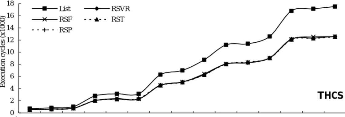
(13) Lists of Figures Figure 2.1. The MDFG example. (a) Nested loops in C code, (b) corresponding MDFG, (c) node types……………………………………….…………11. Figure 2.2. Retiming example. (a) Retimed MDFG of Figure 2.1(a), (b) schedule before retiming, (c) schedule after retiming…………………………...12. Figure 2.3. (a) Original iteration space, (b)(c) changed iteration spaces…………..13. Figure 3.1. (a) MDFG fragment, (b) scheduling result of RSVR………………….23. Figure 3.2. Variable partition results of MDFG in Figure 2.1(b). (a) Based on rightmost indices, (b) based on leftmost indices……………………....24. Figure 3.3. Two consecutive iterations of nested loop in Figure 2.1(a)…………....25. Figure 3.4. The entire scheduling steps of RSF…………………………………....25. Figure 3.5. The entire scheduling steps of RST…………………………………....26. Figure 3.6. (a) Unfolding MDFG of Figure 2.1(b), (b) tiled MDFG of Figure 2.1(b)…………………………………………………………………...26. Figure 3.7. Scheduling results of Figure 2.1(b). (a) RSVR, (b) RSF, (c) RST….…26. Figure 3.8. (a) Unfolded nested loop in canonical form, (b) two consecutive iterations……………………………………………………………….27. Figure 3.9. (a) Tiled nested loop in canonical form, (b) two consecutive iterations 28. Figure 3.10 The entire scheduling steps of RSP……………………………………29 Figure 3.11 Loop parallelization algorithm………………………………………...29 Figure 3.12 (a) The parallelized MDFG of Figure 2.1(b), (b) scheduling result of Figure 2.1(b) using RSP……………………………………………….30 Figure 3.13 The unfolded MDFG of Figure 3.12(b)………………………………..31 Figure 3.14 Overall schedule lengths of DSP applications (1 function unit, 2 memory banks)…………………………………………………………………..35. xi.
(14) Figure 3.15 Overall schedule lengths of DSP applications (1 function unit, 2 memory banks)…………………………………………………………………..36 Figure 4.1. Data ALU block diagram. (a) DSP56000/DSP56001, (b) DSP56300 family…………………………………………………………………..40. Figure 4.2. Motorola DSP56000 architecture……………………………………...41. Figure 4.3. The entire scheduling steps of RSSP…………………………………..43. Figure 4.4. The TDAG constructing algorithm…………………………………….44. Figure 4.5. (a) Two cases of removing memory accesses, (b) TDAG of MDFG in Figure 2.1(b)…………………………………………………………...45. Figure 4.6. (a) A TDAG fragment, (b) after inserting the register transfer vk……...46. Figure 4.7. The register transfer inserting algorithm………………………………46. Figure 4.8. The Gop and Gpr constructing algorithm……………………………….47. Figure 4.9. The Mark_Edge algorithm……………………………………………..47. Figure 4.10 The Check_Cycle algorithm…………………………………………...48 Figure 4.11 Two Gop fragments with accumulator spill…………………………….48 Figure 4.12 The memory access inserting algorithm……………………………….49 Figure 4.13 Scheduling steps of RSSA. (a) An TDAG example, (b) ALU instruction only, (c) initial scheduling result, (d) retimed scheduling result………50 Figure 4.14 Overall schedule lengths of DSP applications…………………………55 Figure 4.15 Overall schedule lengths of DSP applications…………………………56 Figure 5.1. An example of code compaction. (a) Uncompacted code, (b) compacted code, (c)(d) two scheduling results after resource assignment………...61. Figure 5.2. The entire scheduling steps of RSSA………………………………….63. Figure 5.3. The Gop example. (a) TDAG, (b) corresponding Gop…………………..64. Figure 5.4(a) Gop nodes only scheduling result of Figure 5.3(a), unlimited resource 64 Figure 5.4(b) Gop nodes only scheduling result of Figure 5.3(a), with unlimited xii.
(15) number of registers…………………………………………………….66 Figure 5.4(c) Gop nodes only scheduling result of Figure 5.3(a), without accumulator spills……………………………………………………………………67 Figure 5.4(d) The initial scheduling result of Gt of Figure 5.3(a)……………………68 Figure 5.4(e) The retimed scheduling result of Gt of Figure 5.3(a)………………….70 Figure 6.1. An example of TDAG and sharing sets………………………………..85. Figure 6.2. Scheduling results of Figure 6.1. (a) RSSA, (b) RSOR……………….85. Figure 6.3. The overall scheduling algorithm of RSOR…………………………...86. Figure 6.4. The MDFG example…………………………………………………...91. Figure 6.5. The MDFG reconstructing algorithm………………………………….92. Figure 6.6. An example used to illustrate steps of RSER………………………….94. Figure 6.7. The overall scheduling algorithm of RSER……………………………95. Figure 6.8. The corresponding TDAG of (a) Figure 6.6(a), (b) Figure 6.6(d)……..96. Figure 6.9. Scheduling results of Figure 6.6(a). (a) RSOR, (b) RSER…………….96. Figure 6.10 Experimental results of DSP applications (1 function unit, overall schedule length)………………………………………………………103 Figure 6.11 Experimental results of DSP applications (2 function unit, overall schedule length)………………………………………………………104 Figure A.1. Iteration spaces of a loop with depth one. (a) Original, (b) applying RSVR, (c) applying RSF……………………………………………..118. Figure A.2. Iteration spaces of a loop with depth two. (a) Original, (b) applying RSVR, (c) applying RSF, (d) applying RST………………………….119. Figure A.3. Iteration spaces of a loop with depth two. (a) Original, (b)(c) applying RSP…………………………………………………………………...121. Figure B.1. Iteration spaces of a loop with depth one. (a) Original, (b) applying RSOR(RSVR), (c) applying RSOR(RSF)……………………………124 xiii.
(16) Figure B.2. Iteration spaces of a loop with depth one. (a) Original, (b) applying RSER(RSVR), (c) applying RSER(RSF)…………………………….124. Figure B.3. Iteration spaces of a loop with depth two. (a) Original, (b) applying RSOR(RSVR), (c) applying RSOR(RSF), (d) applying RSOR (RST)126. Figure B.4. Iteration spaces of a loop with depth two. (a) Applying RSER(RSVR), formula (B.8), (b) applying RSER(RSVR), formula (B.9)…………..127. Figure B.5. Iteration spaces of a loop with depth two. (a) Applying RSER(RSF), formula (B.10), (b) applying RSER(RSF), formula (B.11)…………..129. Figure B.6. Iteration spaces of a loop with depth two. (a) Applying RSER(RST), formula (B.12), (b) applying RSER(RST), formula (B.13)…………..130. xiv.
(17) Chapter1. Introduction 1.1 The Practicability of DSP Most scientific and digital signal processing applications, such as fluid dynamics, weather forecasting, image processing, video compression, and speech recognition are iterative and usually represented by uniform nested loops [1-5]. All these applications belong to data-dominated category, which are characterized by a predominance of arithmetic instructions and an absence of control-flow within the data path [5]. A digital signal processor (DSP) is a special-purpose microprocessor that is designed and produced to better match DSP applications [3, 6-8]. Unlike general-purpose microprocessors, the DSP design is based on the Harvard architecture, and often includes several independent function units those are capable of operating in parallel [3, 7-8]. In order to meet ever-increasing demands for higher performance and stringent power requirement, such DSPs commonly employ architectures with irregular data paths, heterogeneous register sets, and multiple data memory banks [9]. For the data path, this architecture has multiple small register files dedicated to different sets of function unit instead of a large number of centralized homogeneous registers. In addition, because multiple data memory banks are connected through independent data buses, variables can be partitioned into separate banks and accessed simultaneously. These architectural features are supported by some embedded DSP families, such as Motorola DSP56000 [10], Analog Device ADSP2100 [11], NEC uPD77016 [12], and Texas Instruments TMS320C6000 [13]. Although parallel access, which is enabled by multi-bank memory, is useful to explore the potential of higher memory bandwidth, it gives rise to the problem of how to partition the variables into multiple data memory banks [6, 9, 14-20]. Similarly, using heterogeneous register sets can decrease the architectural complexity but. 1.
(18) increase the difficulty of deciding which register set to use for a certain instruction [9, 17, 21-23]. It is well known that compilation techniques for general-purpose microprocessor do not adapt well to the irregularities of DSP. Therefore, to harvest the benefits provided by DSPs with irregular architectural features, adequate compiler support is obviously essential [3, 8]. Many researches seek to design code generation methods for specific DSP architectures to fully use their features. The complete code generation process for DSP with multiple data memory banks must include five phases: intermediate representation, code compaction, instruction scheduling, memory bank assignment (or variable partition), and accumulator/register assignment [17]. These phases can be performed individually in various sequences because they are logically independent. Meanwhile, because they are extremely data dependent, considering more phases at the same time may lead more effective results. Since nested loops are the most timecritical section in such DSP applications, their execution time will dominate the entire computational performance. To optimize the execution rate of such applications we need to explore the embedded parallelism of a loop. Moreover, due to strict resource constraints of the DSP architecture, accumulator/register spills will supposedly occur very often compared to general-purpose microprocessor. If more spill codes are added, not only the schedule length may be lengthened, but also consumes more power to execute those additional instructions. That is, in addition to increase the instructionlevel parallelism, how to avoid generating too many spill codes is also an important issue of designing the code generation method for DSP architecture.. 1.2 The Power Constraint of DSP Until 1980’s, throughput and latency are two important factors used to determine the quality of an embedded system. In 1990’s, as the portable system such as cellular 2.
(19) phone or portable electronic devices grows rapidly, power consumption becomes another important constraint in the design specification [24]. Because low power is now one of the major concerns in system design, this has forced to analyze and optimize power in all components of a system [25]. Most research to date on power minimization in DSPs is focused on hardware solution. However, if we consider low power design at higher levels of abstractions, we can apply various transformation techniques to system design with wider view and obtain much more effective power reduction with less cost and effort [24, 26]. High-level synthesis techniques for low power have mostly targeted datadominated designs [5]. In a data-dominated application specific circuit such as DSP, it is the power consumed in the data path, including function units, registers, and interconnections, that accounts for a large fraction of the overall power budget [24]. Power consumption is mainly considered in the function units, among units that compose a data path [4, 27]. As shown in [4], authors present that function units account for over 80% of the total data path power, if the data path contains n function units, 4n registers, and 8n multiplexers. Authors of [24, 28] further show that if the overall system is divided into components including data path, clock, and controller, function units will contribute about 40%~60% power to the overall system. Therefore, if we can reduce power consumed by function units, the entire power consumption of the system can be reasonably decreased. In most cases, the power consumed by a resource mainly depends on the input switching activity induced by the data being stored or processed [29]. For a function unit, the power consumption will be reduced by reducing the switching activity involving its input signals [28]. Many researches on power minimization in high-level synthesis attempt to reduce the input activity of function units. Operand sharing is one of these techniques, which binds one identical function unit to more than two 3.
(20) instructions containing at least one common operand, and any instruction without a common operand does not intervene between these instructions [28]. As presented in [27], the average power consumption of a multiplication (or an addition) when one of its operands remains unchanged with respect to the previous instruction is 35% (or 25%) less than when both operands change. Therefore, to increase the potential for a function unit to reuse an operand, the average power consumption of the function unit is dramatically lower. Operand sharing also assists in reducing the number of memory accesses, which tends to prevent the limited number of memory ports from increasing system latency. Furthermore, as shown in [28], because the power consumed by components other than function units are little increase or no increase at all after applying operand sharing, operand sharing is obviously an appropriate technique in low power design.. 1.3 Our Studies in this Thesis Many DSP applications usually contain repetitive groups of operations, which are easily represented by uniform loops and modeled by multi-dimensional data flow graph (MDFG) [2-3]. From above descriptions, clearly that the code generation plays an important role to harvest benefits provided by irregular DSP architectures. With appropriate instruction ordering sequences, we can obtain scheduling results with shorter schedule length, smaller codes size, or less power consumption. In this thesis we focus on designing code generation methods to schedule uniform loops on DSP with multiple data memory banks. Our three study issues are presented as follows.. 1.3.1 Variable Partition Mechanisms For the architecture with multiple data memory banks, the performance gain strongly depends on variable partition and instruction scheduling techniques. Hence, 4.
(21) our first issue is about variable partition. At first we analyze a related method rotation scheduling with variable repartitioning (RSVR) [30] in some detail. We claim that although RSVR is effective, it uses complex mechanisms to partition variables initially and repartition them during instruction scheduling. Note that a variable in MDFG indicates an array not just a single scalar. Therefore, we present three efficient variable partition mechanisms directly according to their array indices. After transforming the given MDFG by appropriate techniques such as unfolding [31], tiling [32], and unimodular transformations [33], we apply the multi-dimensional rotation scheduling [34-35] to schedule instructions. Three code generation methods named rotation scheduling with unfolding (RSF), rotation scheduling with tiling (RST), and rotation scheduling with parallelization (RSP) are proposed corresponded to different variable partition mechanisms [14, 36]. Without repartitioning variables during instruction scheduling, our three methods are obviously efficient compared to RSVR. Moreover, we also define an analytic model to calculate the overall schedule length of an entire retimed loop. Several MDFGs represented DSP applications are selected for performance evaluations. From evaluation results, our methods RSF, RST, and RSP can achieve effective results compared to RSVR, for both a single repetitive iteration and the entire retimed loop. Moreover, the enlarged graph gives a more global view of the data dependencies, which is beneficial for exploring the instruction-level parallelism between different iterations. As for the effectiveness among methods RSF, RST, and RSP, the answer will depend on the topology and loop-carried dependencies of the given nested loop. We also list comparisons among three proposed methods and suggest which method is suitable based on loop-carried dependencies the given MDFG has. Variable partition mechanisms proposed in RSVR and our three methods will be applied in subsequent several studies.. 5.
(22) 1.3.2 Code Generation Methods for DSP with Multiple Data Memory Banks In section 1.1 we have introduced that the complete code generation process for DSP with multiple data memory banks must include five phases. RSF, RST, and RSP have covered all except the accumulator/register assignment phase. Besides, above methods directly use data memory to store and reload operands, so many unnecessary memory accesses may be generated to degrade the performance. Since considering more phases in a code generation method may lead more effective results, we will design a new method to include accumulator/register assignment and further improve overall performance. The proposed method rotation scheduling with spill codes predicting (RSSP) is focus on Motorola DSP56000 [37]. Its main feature is to predict the occurrence of accumulator/register spills in advance, and schedule corresponding spill codes in parallel with other instructions. In addition, we also define a translated data acyclic graph (TDAG) constructed from the given MDFG, in order to remove possible unnecessary memory accesses. We still use selected MDFGs and the analytic model proposed above to evaluate RSSP. Apparently that RSSP outperforms all of RSF, RST, and RSP, because RSSP schedules instructions based on the TDAG which contains less instructions than the MDFG. Comparing to other related studies, RSSP still has advantages of shorter schedule length, for both a single repetitive iteration and the entire retimed loop. RSSP looks quite effective and efficient, but it is not scalable and specifically designed for Motorola DSP56000. Hence, we will generalize it to suit various DSPs with similar architectural features, and propose another method rotation scheduling with spill codes avoiding (RSSA) [38]. The scheduling goal of RSSA is to achieve shorter schedule length and fewer spill codes. In RSSA we design another mechanism to resolve accumulator spills instead of to predict their occurrences, because the predicting results become inaccurate easily when the target architecture is no longer 6.
(23) specific. Moreover, we also integrate these mechanisms into instruction scheduling phase to make RSSA more efficient. We evaluate RSSA according to two metrics schedule length and instruction count at the same time. Suppose the target architecture equals to the Motorola DSP56000, our RSSA usually achieves the shortest schedule length and considerably fewer spill codes compared to other related studies. The main reason is that RSSA can fully utilize system resources and insert spill codes only when required. On the other hand, in addition to design effective code generation method, increasing the number of resources is essentially a more direct way to achieve effective scheduling results. Hence, we also define a parameterized machine model to simulate architectures with different number of resources. After evaluating MDFGs using RSSA on this hypothetical machine model, the influence of differing number of resources on the scheduling results is further deep studied in this thesis. Finally, we describe that with minor modifications, our hypothetical machine model and RSSA is capable for applying to DSP families such as Motorola DSP56000 [10], Analog Device ADSP2100 [11], NEC uPD77016 [12], and Texas Instruments TMS320C6000 [13]. This indicates that the proposed machine model and code generation method have enough flexibility, which are suitable to DSPs with various architectural features.. 1.3.3 Energy-efficient Code Generation Methods As mentioned in section 1.2, low power consumption becomes another important constraint in the DSP design specification in addition to shorter schedule length and less spill codes. To increase the potential for a function unit to reuse an operand is an appropriate way, because the power consumed by function units will be dramatically lower. Therefore, in the third issue of this thesis, we will propose energy-efficient code generation methods based on the operand sharing technique. At first we analyze 7.
(24) RSSA in view of low power consumption. Then, rotation scheduling with operand reutilization (RSOR) is proposed by integrating the operand sharing technique into RSSA, where the original features of RSSA are all retained. In RSOR we add a mechanism to group ALU instructions sharing the same operand into a sharing set. Then, the same scheduling steps used in RSSA are applied, and instructions belong to a sharing set are restrictively scheduled at consecutive time steps to reuse operands. According to preliminary evaluations, because we restrict the execution sequence of some ALU instructions to achieve operand reusing, schedules generated by RSOR may be slightly longer and with more instruction count compared to RSSA. Unfortunately, common operands are not encountered very frequently in real designs, resulting in few opportunities of operand sharing, and hence insignificant power reduction [29]. Nevertheless, instructions with common operands may be hidden inside the original MDFG, which can be generated using some loop transformation techniques. Thus, we proposed another method rotation scheduling with exploiting operand reutilization (RSER), which is extended from RSOR and aimed to further explore potential operand sharing between different iterations. In RSER we define an exploitable sharing set to group load variable instructions reference the same array element in different iterations. An MDFG reconstruction algorithm is also designed based on the retiming [39] technique, to concentrate instructions in a same exploitable sharing set into the same iteration. Then, RSOR is applied to schedule the reconstructed MDFG, so operand sharing within an iteration and existing in different iterations can be both explored in RSER. Metrics including schedule length, instruction count, the number of operands been reused, and information provided from [20] are used to evaluate RSOR and RSER. Besides, we extend the analytic model defined before, to calculate the overall schedule length and the number of operands been reused for the entire retimed loop. From evaluation results, we find that 8.
(25) both RSOR and RSER can successfully explore operand sharing within an iteration. Using RSER further can achieve more number of operands been reused, which indicates that exploiting the operand sharing in different iterations is beneficial for energy-efficient instruction scheduling. On the other hand, because some ALU instructions are restrictively scheduled at consecutive time steps to achieve operand reusing, using RSOR and RSER may generate longer schedules for a single repetitive iteration. However, the overall schedule lengths obtained by RSOR and RSER are still better compared to related studies, because they can effectively explore the instruction-level parallelism between successive iterations. As for the instruction count, the proposed two methods require quite fewer spill codes for a repetitive iteration, but RSER will generate considerable prologue and epilogue codes. That is, if the instruction count is taken as the evaluation metric, RSER will perform poorly compared to related methods.. 1.4 Thesis Organization The remainder of this thesis is organized as follows. Chapter 2 surveys the fundamental background and related work. In chapter 3 we focus on variable partition mechanisms, and introduce three proposed methods RSF, RST, and RSP. Chapter 4 contains an overview of the Motorola DSP56000 architecture, and principles and algorithms of proposed method RSSP are also included. In chapter 5, we present our hypothetical machine model and the general method RSSA, and describe their flexibilities to apply to other real DSP families. Two energy-efficient code generation methods RSOR and RSER extended from RSSA are introduced in chapter 6. Finally, in chapter 7 we list conclusions and plans for future work.. 9.
(26) Chapter 2. Fundamental Background In this chapter, we first model the given problem and survey some fundamentals. Then, we introduce two basic techniques retiming and unimodular transformations widely used in instruction scheduling. After that, related work of our studies in this thesis is presented.. 2.1 Program Model [37-38] Because most scientific and digital signal processing applications usually contain repetitive groups of operations, they can be easily represented by uniform nested loops. A multi-dimensional data flow graph (MDFG) is commonly used to model uniform nested loops. We define the MDFG to be the same as in [37-38], which is slightly different from previous studies [14, 30]. Definition 2.1 A MDFG G = (V, E, X, d, P) is a node-weighted and edge-weighted direct graph, where V is the set of computation nodes; E ⊆ V × V is the edge set that defines the precedence relations; X(e) represents the variable accessed by an edge e; d(e) is a function from E to Zn representing the multi-dimensional delays between two nodes, where n is the number of dimensions; and P(v) represents the node type (see Figure 2.1(c)). Figure 2.1 shows an example of a nested loop and its corresponding MDFG. Nodes in the MDFG include ALU instructions (multiplications and additions), memory accesses (load/store variables and load constants), and register transfers. Note that an edge, e, that does not involve a memory access does not have a label X(e). An MDFG is realizable if there exists a schedule vector s, such that s•d ≥ 0, where d are loop-carried dependencies. A schedule vector s is the normal vector for a set of parallel equitemporal hyperplanes that define a sequence of execution [40]. An. 10.
(27) for i = 1 to m for j = 1 to n D[i, j] = B[i-1, j] × C[i-1, j-2] ; A[i, j] = D[i, j] × 0.5 ; B[i, j] = A[i, j] + 1 ; C[i, j] = A[i, j-1] + 2 ; end end. 0. 1. B. C. (1, 0). 2 D. 14 10. 3. B 12. (a). 4. A 8. P(v) Meaning. (1, 2) 15 11 C 13 A. D 6 A. M Multiplication. 9 (0, 1). 7. A. Addition. L. Load variable. S. Store variable. Multiplication. Load variable. T. Register transfer. Addition. Store variable. C. Load constant. Load constant. Register transfer. 5. (c). (b). Figure 2.1. The MDFG example. (a) Nested loop in C code, (b) corresponding MDFG, (c) node types. iteration is equivalent to the execution of each node in V exactly once. The period during which all nodes in an iteration are executed, according to data dependencies and without resource constraints, is called a cycle period. It is also the maximum execution time among paths that have no delay, which will dominate the entire execution time of a nested loop. Note that many MDFGs can represent a single DSP application, depending on its representation by nested loops.. 2.2 Retiming Technique [39] Retiming is a popular technique that reassigns delays to enhance execution performance for a circuit. For a loop, retiming is a loop transformation technique that can be used to increase the throughput and improve the utilization of resources, by introducing partial overlap between the execution time of successive iterations. The 11.
(28) 0. 1. B. C. (0, 1). 2. 14 (1, -1) D 10. 3. B 12. 4. A 8. 15 11 C. (1, -1). 13. D A (1, -1) 6 A 7. 5. (0, 3). 1 2 3 4 5 6 7 8 9. 9. ALU. M1. M2. 2 13. 0 9 5 10. 1 11 3 4 15. 6. ALU. 7 8 12 14. (b). (-1, 2). prologue. (a) repetitive pattern. r(0) = r(1) = r(2) = (1, -1) r(9) = r(11) = (1, -1). epilogue. (c). p p 1 2 3 4 5 6 7 e e e e e e e. 2 13 6 2 12 13. M1. M2. 0 9 5 10 0 7 8 9 14 5 10. 1 11 3 4 15 1 11. 6. 3 4 15. 7 8 12 14. Figure 2.2. Retiming example. (a) Retimed MDFG of Figure 2.1(a), (b) schedule before retiming, (c) schedule after retiming. retiming vector r(u), a function from V to Zn, represents the offset between the original iteration and that after retiming. A new MDFG Gr = (V, E, X, dr, P) is created after applying r, such that each iteration still has one execution of each node. Delay vectors will be changed accordingly to preserve the original data dependencies. Definitions and properties of retiming are shown below. Definition 2.2 Given any MDFG G = (V, E, X, d, P), retiming function r, and retimed MDFG Gr = (V, E, X, dr, P), we define the retimed delay vector for every edge, path, and cycle, respectively, by: e v, u, v ∈ V and e ∈ E. (a) dr(e) = d(e) + r(u) – r(v) for every edge u → p (b) dr(p) = d(p) + r(u) – r(v) for every path u → v, u, v ∈ V and p ∈ G.. (c) dr(l) = d(l) for any cycle l ∈ G. Based on above definition, MDFGs G and Gr are logically equivalent, and the only difference between them is the delay vectors. Figure 2.2 shows an example of retiming technique. Figure 2.2(a) is the retimed MDFG of Figure 2.1(b), and Figure 2.2(b)(c) list schedules before and after retiming respectively. A prologue is the 12.
(29) (s1, s2) m × n iterations. (a) repetitive pattern. case 1:. s = (1, 0). (b) list. case 2:. s = (s1, s2). (c) prologue + epilogue. Figure 2.3. (a) Original iteration space, (b)(c) changed iteration spaces. instruction set that must be executed to provide necessary data for the iterative process. An epilogue is the complementary set that will be executed to complete the process. If the nested loop contains sufficient iterations, the time required for prologue and epilogue are negligible. Because applying retiming technique will change delay vectors of a realizable MDFG G, we must guarantee the retimed MDFG Gr is still realizable. As mentioned in chapter 2.1, a realizable MDFG G must have a feasible schedule vector s. In [34], it indicates that if we retime MDFG G with a retiming base r orthogonal to s (s ⊥ r), the retimed MDFG Gr is definitely realizable. The feasible retiming base is not unique for a given MDFG, but in [34] it doesn’t propose how to select a best one. In our early study [41], we analyze the relationship between the selection of schedule vector and the change of iteration space in some detail. From analyzing results we find that the overall schedule length is strongly dependent on which feasible schedule vector been selected, especially for nested loops with depth greater than one. If an unsuitable schedule vector is used, the time required to execute prologue and epilogue will occupy considerable part of the overall schedule length. We take a nested loop with depth two as an example. Figure 2.3 shows two cases of modified iteration space after applying retiming technique using different retiming bases. In [41] we prove that the overall schedule length of case 1 is always shorter than or equal to that of case 2, 13.
(30) which implies that s = (1, 0) will be the best selection if it is feasible. Therefore, in [41] we propose a simple algorithm to select the best schedule vector for a given MDFG, which will achieve minimum overall schedule length after applying the retiming technique. We also list a formula to calculate the overall schedule length of a retimed nested loop. This formula will be used to evaluate code generation methods proposed in this thesis.. 2.3 Unimodular Transformations [33] Loop transformation is one of basic techniques for parallel compiler design. It changes the execution sequence of iterations to achieve higher degree of parallelism. Unimodular transformations technique unifies loop permutation, skewing, and reversal, and models them as elementary matrix transformations. All combinations of these loop transformations can simply be represented as products of the elementary transformation matrices. Although unimodular transformations technique is one of the most important techniques used to parallelize uniform nested loops, it doesn’t explain how to use its transformations. In [42] we propose a simple algorithm to parallelize the inner loop of a uniform nested loop with depth two. Note that the transformation matrix to parallelize a nested loop is not unique, and our algorithm can obtain one with minimum skew factor. For a given MDFG G, a new MDFG Gp is created after applying loop parallelization. G and Gp are still logically equivalent, and the only difference between them is the delay vectors, just like applying retiming technique. Some formulas are listed in [42] to calculate the overall schedule length of a parallelized nested loop with depth two. These formulas will be modified further to evaluate one of code generation method proposed in this thesis.. 14.
(31) 2.4 Related Work In this section we survey some related work of our studies. The content of this section is divided into four parts: retiming-based instruction scheduling methods, variable partition mechanisms, code generation methods for DSP architecture with multiple data memory banks, and energy-efficient code generation methods. Some related studies of each part are introduced in the following subsections.. 2.4.1 Retiming-based Instruction Scheduling Methods [34-35, 43] Since retiming technique is useful for generating compact schedules, many instruction scheduling methods are designed based on it to achieve shorter schedule length. Among them, rotation scheduling [43] and multi-dimensional rotation scheduling [34-35] are two effective methods used to schedule MDFG with one or more than one dimensions, respectively. Both these methods contain two main steps. First they simply generate an initial schedule using the list scheduling method under resource constraints. Then instructions scheduled at the first time step are moved to the prologue, and their copies originally resided in the next iteration are rescheduled without violating resource constraints and data dependencies. This step is usually called rotation phase. Corresponding to the given MDFG, the action of rotation is essentially equivalent to retime nodes scheduled at the first time step. For an onedimensional MDFG nodes are always retimed with retiming vector r(u) = 1. As for multi-dimensional MDFG, it must select a feasible retiming base r as the retiming vector. After iteratively applying the rotation phase, a more compact schedule, also with higher throughput, can be obtained. Because these two instruction scheduling methods are really effective and efficient, in this thesis we choose them as the basis to design our own methods.. 15.
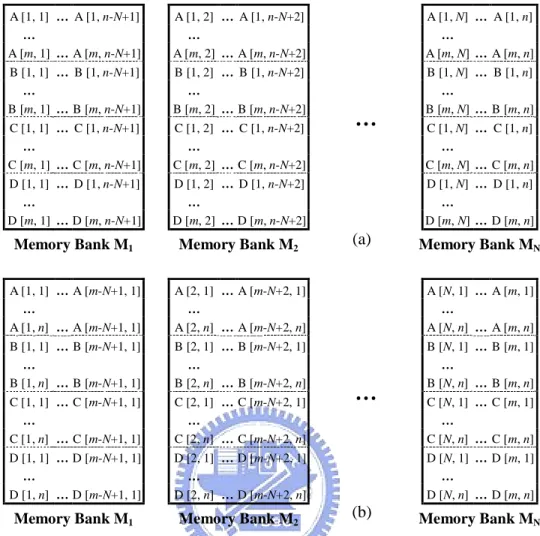
(32) 2.4.2 Variable Partition Mechanisms [15-16, 30] As mentioned in chapter 1, appropriately partition and allocate variables is facilitated to generate more compact schedule in DSP architecture with multiple data memory banks. If two variables may be accessed in parallel, they should be allocated to different data memory banks. Some researches focus on designing variable partition mechanisms which try to evenly distribute memory accesses and explore the potential of higher memory bandwidth. Authors of [15] construct an interference graph (IG) to represent the parallelism available in load instructions for every basic block, and then partition it to determine the allocation of global variables. Two different IG partition heuristics proposed in [15] are based on the same idea: variables will be given higher priority to be stored to different data memory banks if they may be accessed in parallel in a deeper loop. Strictly speaking this mechanism is not accurate enough, because the IG cannot exploit the potential parallelism of memory accesses that reference values produced in different iterations [16]. Therefore, authors of [16] propose another mechanism to recover this flaw by globally constructing the IG for entire functions, and use an integer linear programming approach instead of a heuristic to partition variables. Unlike above methods only focus on variable partition, rotation scheduling with variable repartitioning (RSVR) is designed to resolve both instruction scheduling and variable partition problems [30]. RSVR is modified from rotation scheduling, which considers multiple memory modules while generating a schedule. For a given MDFG, RSVR constructs a corresponding variable independence graph (VIG) to expose all parallel memory accesses. Basically the purpose of constructing VIG is similar as constructing IG in [15-16]. But in RSVR it uses more accurate information to assign edge weights of VIG, so it can achieve better variable partition results. After allocating variables, RSVR applies the same steps as rotation scheduling to schedule instructions. 16.
(33) Besides, when the schedule length cannot be improved in a rotation phase, RSVR will try to repartition variables to shorten the schedule length. In this thesis we will take variable partition as our first study issue. Detailed descriptions and our proposed mechanisms will be presented in chapter 3.. 2.4.3 Code Generation Methods for DSP with Multiple Data Memory Banks [9, 17-23, 44] A complete code generation process for DSP with multiple data memory banks must include five phases: intermediate representation, code compaction, instruction scheduling, memory bank assignment (or variable partition), and accumulator/ register assignment [17]. These five phases can be performed in various sequences due to their logically independent, or be simultaneously considered because they are extreme data dependences. In previous subsection we have listed some methods focus on the variable partition phase. For heterogeneous register sets, authors of [21-23] present specific register allocation algorithms to fit their irregularity. In addition to RSVR introduced above, methods proposed in [18-19] also resolve both instruction scheduling and memory bank assignment problems without considering the limitation of accumulators/registers. Furthermore, methods [9, 17, 20, 44] contain all five phases, and all expect [44] select Motorola DSP56000 as the target architecture. We describe methods [9, 17] in some detail in the following. In the method proposed in [9], its main idea is applying the graph coloring approach to treat variable partition and accumulator/register assignment. For register/ accumulator assignment, authors of [9] specially decouple this phase into two steps. They first classify physical registers into a set of register classes, and allocate each temporary variable to one of the register classes. Next, the graph coloring algorithm is applied to assign each temporary variable a physical register within the register class 17.
(34) previously allocated to it. After generating compacted codes, a weighted undirected graph is constructed based on the sequence of variables referenced in these codes. Then, a maximum spanning tree (MST) of this graph is identified, and variables are assigned also using the graph coloring algorithm. Moreover, authors of this method also propose a heuristic to resolve graph coloring problem. We think the method proposed in [9] is efficient. But it does not present the mechanism to determine and resolve accumulator/register spills, which is definitely required. The method proposed in [17] is an example that simultaneously considers two code generation phases. The Motorola DSP56000 has heterogeneous register sets, so variables referenced from each data memory bank must be loaded in a restricted set of locations. Thus, authors of [17] claim that variable partition and accumulator/register assignment should be performed simultaneously to maximally explore available parallelism among move operations. After generating compacted codes, an undirected graph is constructed representing constrained conditions on the register and memory bank assignments. Then, an algorithm based on graph labeling is used to both memory bank and accumulator/register assignments. Similar as in [9], mechanisms used to insert spill codes are not present in [17]. In addition, authors of [17] suggest applying simulated annealing to resolve the graph labeling problem, which is a time-consuming algorithm and makes the entire method much more complicated. In this thesis, we will study compiler design issues for DSP architecture with multiple data memory banks and heterogeneous register sets. At first we will design a method particularly for Motorola DSP56000. Then, we extend it to a more general method suitable for various DSPs with similar architectural features. Furthermore, this general method is evaluated on various architectures to study the influence of differing number of resources on the scheduling result. Detailed descriptions and our proposed methods will be presented in chapters 4 and 5. 18.
(35) 2.4.4 Energy-efficient Code Generation Methods [4, 20, 24-25, 28, 45-52] In section 1.2, we have introduced the importance of considering low power design at high-level synthesis. Authors of [45] use an experiment setup to physically measure the current being drawn by the CPU during the execution for three architecturally different processors. Based on physical measurements, they develop an instruction-level power analysis technique and an instruction-level power model. The power model consists of three main components: instruction base costs, effect of circuit state, and other inter-instruction effects. The base cost of an instruction is the cost associated with the basic processing required to execute the instruction. The circuit state overhead for a pair of consecutive instructions is used to deal with the switching activity changed between their circuit states. As for the power cost of other inter-instruction effects, it can occur in real programs due to prefetch buffer and write buffer stalls, pipeline stalls, and cache misses. For the DSP architecture, the effect of circuit state change is more marked in terms of power consumption, because its instruction control and data path constitute a larger portion of the silicon. Besides, this instruction-level power analysis technique also provides fundamental information that can guide the development of energy-efficient software. Several ideas in this regard motivated by this analysis are: reduction of memory accesses, energy cost driven code generation, and instruction reordering for low power. For the DSP with multiple data memory banks, instruction packing, parallel memory loads, and swapping operands for multiplications are other possible processor-specific optimizations [25]. Therefore, to reduce the power consumption from software is actually an appropriate way. A number of studies have investigated appropriate scheduling of instructions to reduce the circuit state overhead due to its significant impact on DSP architecture. Methods proposed in [20, 25, 46] are directly based on current measurement technique. They first record base costs of all instructions and circuit state overheads 19.
(36) for different instruction pairs. Then, a ready instruction, which will cost less power after being appended to the current schedule according to measured data, will be selected and scheduled first. Methods proposed in [47-49] attempt low-power schedules with similar mechanisms as previous three methods. But they gather base cost and circuit state overhead information using cycle-accurate simulators SimplePower and SimpleScalar, instead of experimental measurement. Apparently, using above methods can generate schedules with low circuit state overheads. However, the measured data are only dedicated for the selected processor, so these methods are obviously less general. On the other hand, there are lots of researches on power optimization in highlevel synthesis by means of input activity reduction of function units. Authors of [50] reduce the switched capacitance of modules using an iterative improvement technique for scheduling and module allocating. Authors of [51-52] propose similar techniques, to reduce the power by preserving correlation of data inputs to function units through careful binding of instructions to function units. As for methods designed based on operand sharing technique, authors of [4] present list-scheduling algorithm for low power (LPLS), to reduce the activity of the function units by minimizing the switching activity of their input operands. LPLS obviously trades off latency for operand reuse, because instructions with common operands have to be scheduled consecutively and some instruction-level parallelism cannot be successfully explored. However, LPLS performs well only in the cases where common input operands can be identified, but it is not easy to find common input operands in real designs. Therefore, to increase the number of instructions with common operands, a high-level loop transformation technique power-conscious loop folding is presented in [24]. Its main idea is to find instructions sharing an operand in consecutive iterations. Then, a loop folding technique is applied to concentrate these instructions in the same iteration and execute 20.
(37) them consecutively. Alternatively, the method proposed in [28] contains a forcedirected retiming to determine which instruction must be retimed. This technique aims to make as many instructions as possible take common operands as their inputs, and use a list scheduling to perform operand sharing under resource constraints. Comparing instruction scheduling methods listed above, methods designed based on operand sharing are apparently more practical. This is because these methods are not only machine-independent, but also do not require additional memory space to store measured information. In this thesis, we will focus on increasing the potential of operand sharing to design energy-efficient code generation methods. Detailed descriptions and proposed methods will be presented in chapter 6.. 21.
數據
+7


相關文件
In Section 3, the shift and scale argument from [2] is applied to show how each quantitative Landis theorem follows from the corresponding order-of-vanishing estimate.. A number
However, due to the multi-disciplinary nature of this subject, schools may consider assigning teachers with different expertise to teach this subject at different levels (S4, 5
2.1.1 The pre-primary educator must have specialised knowledge about the characteristics of child development before they can be responsive to the needs of children, set
Promote project learning, mathematical modeling, and problem-based learning to strengthen the ability to integrate and apply knowledge and skills, and make. calculated
Using this formalism we derive an exact differential equation for the partition function of two-dimensional gravity as a function of the string coupling constant that governs the
of the spin polarisation L. Bocher et al. submitted (2011).. Mapping plasmons and EM fields Mapping plasmons and EM fields.. New possibilities for studying the low
This kind of algorithm has also been a powerful tool for solving many other optimization problems, including symmetric cone complementarity problems [15, 16, 20–22], symmetric
coordinates consisting of the tilt and rotation angles with respect to a given crystallographic orientation A pole figure is measured at a fixed scattering angle (constant d
