A Flexible Binding Mechanism for ZigBee Sensors
Yueh-Feng Lee, Hsin-Sheng Liu, Ming-Shyan Wei, and Chun-Hao Peng Department of Internet Embedded System (X100)
Information & Communications Research Labs Industrial Technology Research Institute, Hsinchu, Taiwan
yuehfeng_lee@itri.org.tw
Abstract—A unique feature of sensor networks is the
capability of performing actions in response to events detected by sensors. Such a feature requires a mechanism to create an association between the sensor and the actuator, and the resulting association is called a binding. The ZigBee specification defines default binding mechanism called end-device binding. However, this binding mechanism allows only a restricted range of combinations between sensors and actuators. Event filters cannot be defined using this mechanism as well. This paper proposes a flexible binding mechanism for ZigBee sensors called event-action binding, where sensors and actuators can be associated without the constraints imposed by the end-device binding. An event-action binding associates a specific event generated by a sensor with a specific action provided by an actuator. The mechanism supports event filters and multiple event filters can be combined as a composite filter. The binding mechanism was implemented for ZigBee sensors conforming to the specifications of ZigBee home automation and ZigBee cluster library. The implementation is based on YAML descriptions and provides an event matching engine and a browser-based user interface.
I. INTRODUCTION
Sensors and actuators are the most important types of nodes in a sensor network. A crucial feature of sensor networks is that an actuator is able to perform an action in response to a specific event detected by a sensor. In a typical sensor network, such a relationship between a sensor and an actuator is called a binding and can be created by a binding mechanism. When a specific sensor condition is detected, following the binding relationship, the sensor is able to find the target actuator and invokes the correct action. Without binding an actuator could not perform the desired task when interested sensor conditions are detected.
The ZigBee specification [1] defines a default binding mechanism called end-device binding. When establishing an end-device binding, the ZigBee coordinator [1] compares the cluster identifiers [2] supported by the target sensor and the cluster identifiers supported by the target actuator. A binding can be created only when the sensor implements one side (e.g. client side) of one cluster and the actuator implements the other side (e.g. server side) of the same cluster. This binding criterion is not flexible because if the sensor and the actuator do not implement complement sides of the same cluster, a binding can never be created. In addition, event filters [14] cannot be defined using the end-device binding because when an event is detected at the sensor side, a predefined action is always invoked at the actuator side.
The binding flexibility issue of ZigBee can be addressed by two approaches. The first approach is to add the
publish/subscribe layer [5]-[8] on top of the ZigBee network layer but below the ZigBee application layer. In the publish/subscribe setting, a sensor acts as a publisher and an actuator acts as a subscriber. An actuator can freely subscribe data published by a sensor, so the flexibility issue does not exist. Event filters can be defined when the notion of content-based publish/subscribe [5], [6] is used. Since the additional publish/subscribe layer changes the existing ZigBee stack, the binding mechanism adopts this approach is no longer compatible with existing ZigBee sensors and actuators.
The second approach is to develop a rule-based system [15] on top of the ZigBee stack. In the rule-based setting, a binding can be considered as a rule, where the condition to be detected constitutes the left-hand-side of the rule and the actions to be performed constitutes the right-hand-side. Event filters can be defined as part of the left-hand-side. Since this approach needs not modify the protocol stack, the binding mechanism adopts this approach is still compatible with existing ZigBee sensors and actuators. Rule-based system for sensor networks had been addressed by a few researches [9], [10]. However, none of them dealt with the constraints of real and standardized sensor networks, especially ZigBee, and provided a concrete implementation.
In this paper, we propose a binding mechanism for ZigBee sensors, addressing both the flexibility and event filter issues. The mechanism is motivated by the rule-based approach as described. The core concept of the mechanism is called event-action binding, where an arbitrary event generated by an arbitrary sensor can be bound to an arbitrary action supported by an arbitrary actuator. Since the combinations of an event and an action are arbitrary, the flexibility problem is solved. Event filters can be easily inserted between the sensor and the actuator because event detection is processed by a centralized entity such as the data sink. We define event-action binding using markup language syntax instead of programming language syntax. Markup syntax could be more acceptable by typical sensor users because most of them are not experienced programmers. The system also provides a step-by-step user interface that allows the user to create bindings without writing binding specifications.
The proposed binding mechanism was implemented for ZigBee sensors and actuators that conforms to the ZigBee home automation specification [3] and the ZigBee cluster library specification [2]. Since the implementation reuses the information defined in these two specifications rather than changing the specifications, the mechanism is interoperable with existing ZigBee sensors and actuators. The implementation is running on a ZigBee gateway which had
been deployed on a sensor experimental platform [12] in National Tsing Hua University, Taiwan.
The remainder of the paper is organized as follows. Section II introduces sensor binding in general and event-action binding. Section III presents information formats needed in event-action binding, including device descriptions, binding specifications, and sensor data. In Section IV, we describe the implementation of the event-action binding mechanism. Finally, in Section V, the conclusions and the future work are given.
II. CONCEPTSOFBINDING
A. Sensor Binding in General
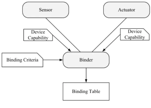
As stated earlier, a binding is an association between a sensor and an actuator. When creating a binding, three major roles are involved: sensor, actuator, and binder, as shown in Fig. 1. The binder, usually the base station of the sensor network, is responsible of determining whether a binding can be created between a sensor and an actuator. When making the decision, the binder requires two types of information: device capability and binding criteria. Device capability describes the functions provided by the sensor and the actuator. A binding criterion uses the device capability to determine whether a binding can be created or not. For the same device capability given, different binding criteria may produce different binding results. When intension of binding is approved by the binder, the information about the binding is stored in a data structure called binding table. The binding table can be located either at the base station or at each sensor. When event occurs, the sensor could look up the binding table to find out the actuator to be manipulated.
Note that sensor binding can also be viewed from the perspective of distributed event-based or publish/subscribe systems [5], [14]. A sensor can be viewed as a publisher and an actuator can be viewed as a subscriber. A major difference from typical publish/subscribe systems is that the events generated by sensors are not directly sent to the actuators. Instead, they should be translated into actions, and then received and executed by the actuators.
B. ZigBee End-Device Binding
ZigBee is probably the wireless sensor network standard providing the most well-defined procedure for creating bindings and such a procedure is called end-device binding. In ZigBee end-device binding, the coordinator of the network acts as the binder. To initiate the binding procedure, the user presses the binding button installed on the sensor. After the button is pressed, the device capability of the sensor is sent to the coordinator. The device capability of the actuator is also sent to the coordinator when the user presses the binding button installed on the actuator. The device capability contains all the cluster identifiers supported by a sensor or by an actuator. After receiving device capability from the both sides, the coordinator compares their supported cluster identifiers. As stated earlier, a binding is valid if the sensor and the actuator implement the complement sides of the same cluster. That is, either the sensor implements the client side and the actuator implements the server side, or the sensor implements the server side and the actuator implements the client side. When the binding request is validated by the coordinator, the coordinator writes the binding information as a binding entry in the binding table. The binding table is located at each sensor and each binding entry is essentially a pair that consists of a cluster identifier and the address of the actuator. When an event occurs at the sensor, the sensor looks up its binding table to find the address of the actuator and then invokes the action command on the actuator.
The inflexibility of ZigBee end device binding can be illustrated by the motion sensor and the on/off light. A ZigBee motion sensor should implement the Intruder Alarm System (IAS) Zone cluster and a ZigBee on/off light should implement the on/off cluster. Since these two devices do not implement the complement sides of the same cluster, a binding can never be created between these two devices, even such kind of combination is quite usual in home security and building automation applications.
The other drawback of ZigBee end-device binding is that event filters cannot be defined as part of a binding. When a binding is established, according to the ZigBee cluster library specification [2], each event is assigned a predefined action. Whenever an event is detected, the assigned action is always invoked by the sensor. There is no mechanism for sensors to apply event filters before invoking the actions.
Binding Table Binder Sensor Actuator Binding Criteria Device Capability Device Capability
Fig. 1. Major roles of binding.
Binder
S1 S2 … SM A1 A2 … AN
Sensor Event Actuator Action … … … … … … … … … Events Actions Binding Table Sensors Actuators … … …
---
ProfileId: 0x0104 DeviceId: 0x0100 DeviceName: On/Off Light NumberOfCluster: 1 ClusterList: ---
ProfileId: 0x0104 DeviceId: 0x0106 DeviceName: Light Sensor NumberOfCluster: 1 ClusterList:
- ClusterName: Illuminance Measurement ClusterId: 0x0400 NumberOfAttribute: 2 AttributeList: - AttributeName: LightSensorType AttributeId: 0x0004 AttributeDataType: ENUM8 AvailableAttributeValue:0x00,0x01 AvailableAttributeAlias:Photodiode,CMOS - AttributeName: MeasuredValue AttributeId: 0x0000 - ClusterName: On/Off ClusterId: 0x0006 NumberOfCommand: 3 CommandList: - CommandId: 0x00 CommandLength: 0 CommandPayload: NULL CommandName: Off - CommandId: 0x01 CommandLength: 0 CommandPayload: NULL CommandName: On AttributeDataType: UINT16
Fig. 3. Device description of light sensor.
- CommandId: 0x02 CommandLength: 0 CommandPayload: NULL CommandName: Toggle
C. Event-Action Binding
In this section we propose event-action binding, a simple yet powerful model that can describe the behavior of most sensors and actuators and lays the foundation of our work. In the event-action binding model, each sensor is capable of generating a set of distinct events and each actuator supports a set of distinct actions. An event-action binding is defined as a relationship that associates a specific event from the set of events provided by a sensor with a specific action from the set of actions supported by an actuator. The structure of event-action binding is shown in Fig. 2. The model does not restrict which event can be associated with which action. Instead, the decision is left to the user or can be made further by the system. For example, suppose that a motion sensor can generate detected and not-detected events and a light supports
on and off actions. We can implement a simple lighting
control mechanism by creating two event-action bindings. One associates the detected event with the on action and the other associates the not-detected event with the off action. Event-action binding differs from ZigBee end-device binding in that each type of sensor does not prescribe which types of actuator to be associated.
III. DEVICE DESCRIPTION AND BINDING SPECIFICATION
The event-action binding mechanism requires three types of supporting information: device description, binding specification, and sensor data. All these information are defined using the YAML language [11]. YAML is a key/value-based markup language that is simpler than XML but is more human readable and easier to be processed by machines. We will briefly introduce ZigBee cluster library specification, which is the device descriptions based, and then describes three types of information format in turn.
A. ZigBee Cluster Library
ZigBee cluster library [2] defines clusters that can be reused in profile specifications such ZigBee home automation profile specification [3]. Each profile defines a set of devices and specifies which set of clusters should be implemented by which device. For example, the home automation profile specifies that an on/off light device should implement the on/off cluster. The ZigBee cluster library specifies the set of commands and attributes supported by a cluster. Basically, an actuator implements the server side of commands and a sensor implements the client side of commands. Thus, a sensor could invoke commands supported by the actuator. The attributes provide information about the status of sensors and are primarily used by a data sink. A data sink can either query the status of attributes or receive the status of attributes sent by a sensor.
Fig. 4. Device description of on/off light.
B. Device Description
A device description describes the types of events generated by a sensor or the types of actions supported by an actuator. A ZigBee-based device description describes clusters, commands, and attributes of a ZigBee device in an organized structure. Since the structure does not violate the home automation and cluster library specifications, the proposed binding mechanism can interoperate with the existing ZigBee sensors and actuators. The device description of a ZigBee light sensor and a ZigBee on/off light are shown in Fig. 3 and Fig. 4, respectively. For example, the motion sensor shown in Fig. 3 defines LightSensorType and MeasuredValue attributes, and the on/off light shown in Fig. 4 defines on, off, and toggle commands. From the viewpoint of binding specification which will be introduced later, any attribute supported by a sensor is considered as an event and any command supported by an actuator is considered as an action.
C. Binding Specification
As described earlier, an event-action binding associates an event generated by a sensor and an action supported by an actuator. Thus, the contents of an event-action binding specification for ZigBee devices depend on the attributes and commands defined in device descriptions. A binding specification consists of two major parts: event filter part and action part. The event filter part specifies the event to be detected with the event filter to be applied. The action part specifies the action to be performed when the event with condition specified by the event filter is satisfied. Fig. 5 shows a binding specification that invokes the on command of the on/off light when the sensed MeasuredValue attribute is less than 500 Lux.
D. Event Filter Model
When defining a binding specification, instead of invoking the action each time whenever an event is received, we can apply an event filter to filter out the uninterested conditions. The binding specification supports two types of event filters: primitive filter and composite filter. A primitive event filter is conceptually expressed as a 5-tuple (sensor address, sensor type, attribute name, relation, value). For example, if we wish to invoke an action when the illuminance measured by the light sensor of address 143E is less than 500 Lux, the resulting event filter is expressed as (143E, light sensor, illuminance, <, 500). The binding specification shown in Fig. 5 consists of such a primitive event filter. The ZigBee extended address is
0x7352B32100888888, the sensor type is light sensor, the
attribute name is MeasuredValue, the relation is LessThan, and the value is 0x01F4.
In our event filter model, multiple primitive event filters can be combined to form a composite event filter. A composite event filter can detect more than one attributes, either from a single sensor or from multiple sensors. Primitive event filters can be combined using Boolean operators, e.g. AND, OR, and NOT. The binding specification shown in Fig. 6 contains a composite filter which detects a composite condition when the motion sensor detects the presence of human and the measured illuminance is less than 500 Lux.
In addition to composite filters, the proposed binding specification also supports composite actions, where more than one action can be invoked when a single event is detected.
---
EventFilterList:
RootFilter: CompositeFilter1 PrimitiveFilter1:
DeviceName: Light Sensor DeviceID: 0x0106
ExtendedAddress: 0x7352B32100888888 EndPoint: 0x14
ClusterName: Illuminance Measurement ClusterID: 0x0400 AttributeName: MeasuredValue AttributeID: 0x0000 AttributeDataTypeName: UINT16 AttributeDataTypeID: 0x21 FilterOperator: LessThan FilterValue: 0x01F4 PrimitiveFilter2:
DeviceName: Motion Sensor DeviceID: 0x0402
ExtendedAddress: 0x00137A00000001CA EndPoint: 0x0B
ClusterName: IAS Zone ClusterID: 0x0500 AttributeName: ZoneStatus AttributeID: 0x0002 AttributeDataTypeName: BMAP16 AttributeDataTypeID: 0x19 FilterOperator: EqualTo FilterValue: 0x0002 CompositeFilter1: Operator: AND Operand1: PrimitiveFilter1 Operand2: PrimitiveFilter2 ActionList:
- DeviceName: On/Off Light DeviceID: 0x0100 ExtendedAddress: 0xCC243000000000AB EndPoint: 0x2F ClusterName: On/Off ClusterID: 0x0006 CommandName: On CommandID: 0x01 CommandPayloadLength: 0 - DeviceName: On/Off Light DeviceID: 0x0100 ExtendedAddress: 0xCC243100000000A9 EndPoint: 0x2F ClusterName: On/Off ClusterID: 0x0006 CommandName: On CommandID: 0x01 CommandPayloadLength: 0
Fig. 6. Binding with composite filter and composite action. ---
EventFilterList:
RootFilter: PrimitiveFilter1 PrimitiveFilter1:
- DeviceName: Light Sensor DeviceID: 0x0106
ExtendedAddress: 0x7352B32100888888 EndPoint: 0x14
ClusterName: Illuminance Measurement ClusterID: 0x0400 AttributeName: MeasuredValue AttributeID: 0x0000 AttributeDataTypeName: UINT16 AttributeDataTypeID: 0x21 FilterOperator: LessThan FilterValue: 0x01F4 ActionList:
- DeviceName: On/Off Light DeviceID: 0x0100 ExtendedAddress: 0xCC243000000000AB EndPoint: 0x2F ClusterName: On/Off ClusterID: 0x0006 CommandName: On CommandID: 0x01 CommandPayloadLength: 0
The action part of the binding specification shown in Fig. 6 defines a composite action that invokes two actions. One is on the sensor of address 0xCC243100000000A9 and the other is on the sensor of address 0xCC243000000000AB.
--- SensorData:
- DeviceName: Light Sensor DeviceID: 0x0106
ExtendedAddress: 0x7352B32100888888 EndPoint: 0x14
ClusterName: Illuminance Measurement ClusterID: 0x0400
AttributeName: MeasuredValue AttributeID: 0x0000
AttributeDataTypeName: UINT16 Value: 0x017B
Fig. 7. Sensor data item generated by light sensor.
E. Sensor Data Format
Once a binding specification is specified, the system should match incoming sensor data against the binding description. Thus, the format of sensor data should be addressable by the binding specification. Conceptually, a sensor data item consists of four basic elements: address, sensor type, name of data, and value. A sensor data item generated by light sensor is shown Fig.7, where the sensor type is light sensor, the name of data is MeasuredValue, and the value is 0x017B.
IV. IMPLEMENTATION
In this section, we introduce the implementation architecture and platform first and then we describe a step-by-step binding interface that aids the user in creating event-action bindings.
A. Architecture and Platform
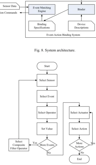
The event-action binding system consists of two major software components: binder and event matching engine. The interaction between the two software components and the three types of information described in the previous section is shown in Fig. 8. The binder provides a browser-based interface for creating bindings and the details are described later. It reads device descriptions and produce binding specifications. The event matching engine matches incoming sensor data against binding specifications and sends action commands when interested events are detected. The current event matching engine is an efficient implementation of the Rete algorithm [13].
The implementation is based on the ZigBee sensor and gateway platform developed by Industrial Technology Research Institute, Taiwan. The gateway is currently an Asus Eee PC or Eee Box with a ZigBee dongle plugged in, which acts as the coordinator of the ZigBee network. All the sensors and actuators are equipped with a CC2430 [4] ZigBee processor made by TI. The current implementation supports five types of sensors and three types of actuators: motion sensor, light sensor, temperature sensor, humidity sensor, and glass-break sensor, on/off light, alarm, and outlet.
B. Step-by-Step Binding Interface
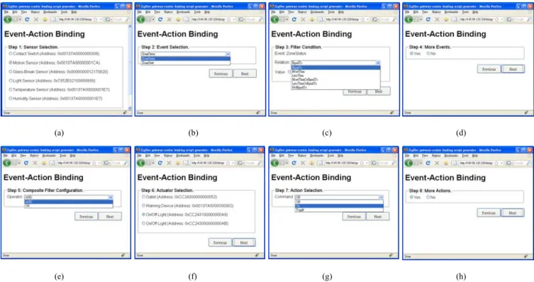
Basically, the user could create a binding by directly writing YAML-based binding specification according to the device descriptions of existing sensors and actuators. In order to reduce the efforts of writing binding descriptions, we also implement a browser-based, step-by-step binding interface. The overall procedure is shown in Fig. 9, and the corresponding snapshots are shown in Fig. 10. The procedure is briefly described as follows. First, the user selects the sensor to be detected. Next, the user chooses the event of the selected sensor and determines the operation and the value of the event filter. If composite filters are needed, the user can select the Boolean operator between the filters and then follows the sensor and filter selection procedure again. After all the sensors and filters are determined, the user selects actuators and the corresponding action commands in a similar way. Finally, the binding interface automatically generates a binding specification and then injects the binding specification into the event matching engine.
Binder Event Matching
Engine
Event-Action Binding System Browser Sensor Data Action Commands Binding Specifications Device Descriptions
Fig. 8. System architecture.
Start Select Sensor
Select Event
Select Operator Select Actuator
Set Value Select Action
More Events More Actions Select Composite Filter Operator Yes No No Yes End
In this paper, a flexible binding mechanism for ZigBee is proposed. Due to the reuse of definitions specified in ZigBee specifications, the implementation is still compatible with existing ZigBee sensors and actuators. A major limitation of the current work is that the event detection should be carried out on a centralized machine, which may consume more network bandwidth. Although distributed event detection in ZigBee is still possible, the solution should modify the code on sensors and actuators and thus is not incompatible with the existing ZigBee devices.
Another feature not considered in the current work is the automation of event-action binding, in which the user only has to select a target sensor and a target actuator, the rest of the work such as paring the events and actions can be automatically performed by the binding system. Automatic event-action binding can be achieved in two directions. One is exploiting the existing capability information such as the ZigBee cluster library. The other is to build a completely new binding model. Our ongoing work is to develop an automatic event-action binding mechanism by reusing the existing capability information as much as possible.
[2] ZigBee Alliance, “ZigBee cluster library specification,” Oct. 2007.
(a) (b) (c) (d)
(e) (f) (g) (h)
Fig. 10. Snapshots of binding interface. (a) Sensor selection. (b) Event selection. (c) Event filter configuration. (d) Decision for composite event (e) Composite filter operator. (f) Actuator selection. (g) Action selection. (h) Decision for composite action.
[3] ZigBee Alliance, “ZigBee home automation public application profile,” version 1.0, Oct. 2007.
[4] Texas Instruments, “CC2430 Data Sheet”, revision 2.1, May, 2007. [5] P. TH. Eugster, P. A. Felber, R. Guerraoui, and A.-M. Kermarrec, “The
Many Faces of Publish/Subscribe,” ACM Computing Surveys, vol.35, pp. 114–131, June. 2003.
[6] A. Carzaniga, D. S. Rosenblum, and A. L. Wolf, “Design and Evaluation of a Wide-Area Event Notification Service,” ACM
Transactions on Computer Systems, vol.19, No.3, pp. 332–383, Aug.
2001.
[7] E. Souto, G. Guimaraes, and G. Vasconcelos, “A Message-Oriented Middleware for Sensor Networks”, in Proc. of Int. Workshop on
Middleware for Pervasive and Ad-Hoc Computing (MPAC), 2004.
[8] P. Costa, G. P. Picco, and S. Rossetto, “Publish-Subscribe on Sensor Networks: A Semi-probabilistic Approach,” in Proc. of IEEE Int. Conf.
on Mobile Ad-hoc and Sensor Systems (MASS05), 2005.
[9] K. Terfloth, G. Wittenburg; and J.Schiller, “FACTS - A Rule-Based Middleware Architecture for Wireless Sensor Networks”, in Proc. of
IEEE Int. Conf. on Communication System Software and Middleware (COMSWARE), 2006.
[10] X. Fei and E. H. Magill, “Rule execution and event distribution middleware for PROSEN-WSN”, in Proc. of Int. Conf. on Sensor
Technologies and Applications (SENSORCOMM), 2008
[11] O. Ben-Kiki, C. Evans, and I. döt Net, “YAML Ain’t Markup Language (YAML) Version 1.1,” Jan. 2005. [12] S.-P. Kuo, C.-Y. Lin, Y.-F. Lee, H.-W. Fang, Y.-W. Hong, H.-C. Lin,
Y.-C. Tseng, C.-T. King, C.-L. Wang, “The NTP Experimental Platform for Heterogeneous Wireless Sensor Networks”, in Proc. of Int.
Conf. on Testbeds and Research Infrastructures for the Development of Networks & Communities (TRIDENTCOM), 2008.
ACKNOWLEDGMENT
The author would like to thank the anonymous reviewers for their valuable suggestions. This work was supported by the Ministry of Economic Affairs of Taiwan, R.O.C., under Grant
98-EC-17-A-02-01-0617. [13] C. Forgy, "Rete: A Fast Algorithm for the Many Pattern/Many Object Pattern Match Problem", Artificial Intelligence, vol. 19, pp 17–37, 1982.
[14] G. Muhl, L. Fiege, and P. Pietzuch, Distributed Event-Based Systems. Berlin, Heidelberg: Springer-Verlag, 2006.
REFERENCES
[15] P. Jackson, Introduction to Expert Systems. Reading, Mass: Addison-Wesley, 1999.
[1] ZigBee Alliance, “ZigBee specifications,” version r13, Dec. 2006.