國立交通大學
電子工程學系 電子研究所碩士班
碩 士 論 文
使用蒙哥馬利次方梯和混沌亂數產生器的RSA密碼系統
An RSA Cryptosystem Based on Montgomery
Powering Ladder and Chaos-based Random Number
Generator
學生:陳勇志
指導教授:張錫嘉 教授
使用蒙哥馬利次方梯和混沌亂數產生器的RSA密碼系統
An RSA Cryptosystem Based on Montgomery Powering Ladder
and Chaos-based Random Number Generator
研 究 生:陳勇志 Student:Yung-Chih Chen
指導教授:張錫嘉 教授 Advisor:Hsie-Chia Chang
國 立 交 通 大 學
電子工程學系 電子研究所 碩士班
碩 士 論 文
A ThesisSubmitted to Department of Electronics Engineering & Institute Electronics College of Electrical and Computer Engineering
National Chiao Tung University In Partial Fulfillment of the Requirements
for the Degree of Master of Science
In
Electronics Engineering September 2010
Hsinchu, Taiwan, Republic of China
i
使用蒙哥馬利次方梯以及混沌亂數產生器的RSA密碼
系統
學生:陳勇志 指導教授:張錫嘉 教授
國立交通大學
電子工程學系 電子研究所碩士班
摘 要
本論文提出了在RSA密碼系統上可擴展的實作方法。這項設計的架
構採用改良的蒙哥馬利模數乘法器以及蒙哥馬利次方梯演算法。可支
援4096位元以下的所有長度。本論文提出的演算法比較傳統的模數指
數運算設計有更快的速度。在RSA加密運算中,針對1024位元、2048
位元、4096位元公鑰的運算時間分別需要3.5ms、13.7ms、106ms。
另外我們改進了混沌映射基礎下的亂數產生器。在sp800-22測試下,
此設計比較傳統設計有更高的通過率。此設計嵌入在RSA密碼系統中
抵抗SPA和DPA攻擊而不用增加額外乘法運算的時間。
ii
An RSA Cryptosystem Based on Montgomery
Powering Ladder and Chaos-based Random Number
Generator
Student:Yung-Chih Chen Advisor:Dr. Hsie-Chia Chang
Department of Electronics Engineering
Institute of Electronics
National Chiao Tung University
Abstract
This thesis introduces a scalable hardware implementation of RSA cryptosystem. The architecture of this work is modified by the Montgomery modular multiplier and it based on Montgomery powering ladder algorithm. It can work in any length less than 4096-bit. This proposed algorithm provides a shorter latency on modular exponentiation operations than other works. It takes 3.5 ms, 13.7 ms, and 106 ms to complete a 1024-bit, 2048-bit, and 4096-bit key length of RSA calculation time respectively.
Furthermore, we modify random number generator based on chaotic map. Testing by SP800-22, this work has higher passing rate than previous work. This embedded in RSA cryptosystem for against SPA and DPA without extra cycle for processing multiplications.
iii
誌 謝
這本論文的完成,一路上有許多人的協助與付出,我很幸運研究的路上不是 孤獨的。首先感謝交通大學提供一個優良的環境,無論是學業、社團或是生活上, 都是豐富且充實。我很慶幸人生的精華時間能與這個美麗的學校共處。再者感謝 我的指導教授張錫嘉博士,從我進大一以來就是老師的導生,一直到研究所也還 是在老師的研究室學習,從學術討論到生活瑣事通通都是聊天的內容,這也讓我 體認什麼是身為一個師長的表率,並且覺得進入OASIS實驗室中是人生中非常光 榮的時刻。 再來要感謝Star group 的全部成員,林建青學長帶領我進入這個團體,認 識了密碼的領域。劉柏均學長與李人偉學長時常在我遇到問題時,給予我解答與 協助,以順利完成研究進度。廷聿、耀琳、如宏、靜瑜是一起奮鬥的夥伴,在遇 到苦悶時可以一起挖苦,一起努力。還有其他Si2與OASIS實驗室中的好同學們, 在一起的時候就像是一家人,永遠是那麼溫暖 最後還要謝謝我的父母與姐姐,給予我金錢上的支援,讓我可以無後顧之憂 的心情下全力為學業衝刺,儘管家人也都有自己的工作與家務,但是還是以我的 學業為第一優先支持我。謝謝你們的愛與包容。僅以此篇論文與一路上幫助過我 的人分享這份喜悅。iv
An RSA Cryptosystem Based on Montgomery
Powering Ladder and Chaos-based Random Number
Generator
Student:Yung-Chih Chen
Advisor:Hsie-Chia Chang
Department of Electronics Engineering
National Chiao Tung University
v
Content
摘 要 ... i Abstract ... ii 誌 謝 ... iii Content... v 1 Introduction ... 1 1.1 Background ... 1 1.2 Motivation ... 3 1.3 Thesis Organization ... 42 RSA Cryptosystem and Random Number Generator ... 5
2.1 Mathematics Foundation ... 5 2.1.1 Number Theory ... 5 2.1.2 Montgomery Method ... 8 2.2 RSA Algorithm ... 10 2.2.1 RSA Scheme ... 10 2.2.2 R-L and L-R Algorithm ... 12
2.2.3 Montgomery Powering Ladder ... 13
2.3 Power Analysis ... 14
2.3.1 Simple Power Attack (SPA)... 15
2.3.2 Differential Power Attack (DPA) ... 16
vi
3 Proposed RSA Architecture ... 19
3.1 Word-based Montgomery Multiplication ... 19
3.1.1 Proposed Word-based Montgomery Multiplication Architecture I ... 21
3.1.2 Proposed Word-based Montgomery Multiplication Architecture II ... 22
3.2 Architecture of Proposed Montgomery Multiplier ... 26
3.2.1 Processing Unit ... 26
3.2.2 Number of Processing Unit Size of Word ... 27
3.2.3 Montgomery Multiplier with Flexible Length... 28
3.3 Random Bit Generator ... 29
3.3.1 Random Bit Generator from Chaotic Map ... 29
3.3.2 Proposed Dynamic Random Bit Generator ... 31
3.4 Proposed RSA Crypto-core with RNG ... 32
4 Implement Result and Comparison ... 36
4.1 RNG Testing ... 36
4.2 Implement with Cell Base Design ... 38
5 Conclusion ... 41
vii
List of Figures
1.1 Public key system model………..2
2.1 Block diagram of random number generator………..…18
3.1 Block diagram of proposed word-based Montgomery multiplication I…….….22
3.2 Block diagram of proposed word-based Montgomery multiplication II……....22
3.3 Latency comparison………25
3.4 Architecture of processing unit………...26
3.5 Configurations of n=1024………...……28
3.6 Block diagram of proposed RNG………30
3.7 Block diagram of RSA cryptosystem with two Montgomery multipliers……...33 3.8 Block diagram of RSA cryptosystem with three Montgomery multipliers….…34
viii
List of Tables
3.1 Four parameters………..32 4.1 Comparison with RNG passing SP800-22……….37 4.2 The verification results on ASIC………....38 4.3 Comparison with other 1024-bit modular multiplier with cell base design…...39 4.4 Comparison with other 1024-bit RSA cryptosystem with cell base design……40
1
Chapter 1
Introduction
1.1 Background
As science and technology progress, Cryptography has become an important knowledge for protecting people‟s private information. Information may be transported through by mobile phone, ATM cards, the Internet, etc. People depend on the tools sending message that may be secret or important. If there is no protector between communication, the hacker would get the message easily.
There are two kinds of commonly used cryptosystem ways: Secret-key cryptosystem and public-key cryptosystem. The former is a conventional and simple method. It use the same key to encrypt and decrypt. This method is known as symmetric cryptosystem. There are many algorithms proposed for the symmetric cryptosystem, such as DES(Data Encryption Standard) and AES(Advanced Encryption Standard). A secure channel is needed between sender and receiver to exchange the key, but how to get this channel also is a problem. We call it key distribution problem.
2
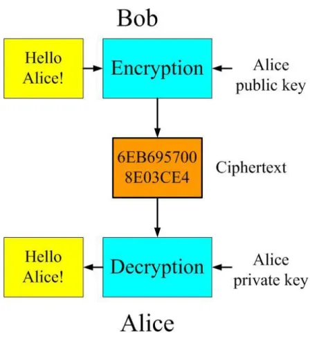
Hellman. This is the first method for sharing secret-key over an unprotected communications channel without prior secure channel, which came to be know as Diffie-Hellman key exchange method. Figure 1.1 shows a scheme of public key system. In an encryption scheme anyone can encrypt using the public key, but only the holder of the private key can decrypt it. People do not need secure channel to exchange secret key anymore.
Figure 1.1: Public key system model
RSA[2] is the popular public-key cryptosystems widely used nowadays. It is based on the high difficulty of factoring large numbers. Rivest, Shamir and Adleman established this method at MIT in 1978. It is widely used to ensure data privacy in many fields. PKCS#1 standards[4] lines out a way of encrypting data or digital signature using the RSA cryptosystem. In recent decades, RSA cryptosystem are applied in the modern information technology.
3
RSA cryptosystem is based on modular exponentiation. It is easy to implement by repeat modular multiplications. Modular multiplication has to be performed a certain number of times depends on the key length to ensure security, but consequence is that the RSA operation has to take much more computational cost for security consideration. In order to include RSA cryptosystem practically for high speed application, it is desired to devise faster encryption and decryption operations.
1.2 Motivation
There are many applications using RSA as authentication for transactions and encryptions or signature for secure messaging, for example, virtual private networks, electronic commerce, and secure Internet access. The precision of operands is getting higher for better security. A major design concern for multiplication units used in cryptography is the large number of operand bits, which causes large fanout of signals, large wire delays, and complex routing.
Word-based method can solve the high fanout problem. The precision of operand is limited only by the memory. Any length less than 2048-bit can be performed in this thesis.
Recent researches showed that power consumption may reveal the secret key. Those attacks, such like SPA and DPA, work based on the statistic analysis of power tracing. It is essentially to design some extra circuits to against the power attack.
4
1.3 Thesis Organization
In this thesis, the scalable RSA cryptosystem is given. In Chapter 2, the preliminary mathematical background of RSA is first introduced. And then we describe the Montgomery multiplication and modular exponentiation algorithms which used in RSA cryptosystem. Third, we introduce power analysis method. In the end of this section, we discuss about random number background knowledge.
In Chapter 3, architecture of word-based Montgomery multiplication over prime field is proposed. Second, we proposed a modified random number generator for high passing rate of test. Finally, we introduced total architecture of RSA cryptosystem which against power attack by adding random number generator.
In Chapter 4, it shows the hardware implementation results and comparison for ASIC and test results for proposed random number generator. Conclusion is given in Chapter 5.
5
Chapter 2
RSA Cryptosystem and Random
Number Generator
2.1 Mathematics Foundation
This chapter introduces the basic arithmetic used in RSA cryptosystem over GF(p). Modular arithmetic such as modular multiplication is especially an important part in the RSA systems.
2.1.1 Number Theory
Congruences
One of the most basic and useful in number theory is modular arithmetic, or congruences. Let a, b, n be integers with n≠0. If a and b differ by a multiple of n, a is congruent to b mod n.
6 It can be rewritten as
a≡b + nk
For some integer k
Primitive Roots
In general, when p is a prime, a primitive root mod p is a number whose powers yield every nonzero class mod p. There are φ (p-1) primitive roots mod p. Let g be a primitive root for the prime p.
.If i is an integer, then gi≡1(mod p) if and only if i≡0(mod p-1). .If j and k are integers, then gi≡ gk
(mod p) if and only if j≡k(mod p-1).
Fermat’s Theorem
Fermat‟s theorem states the follows: If p is prime and a is a positive integer not divisible by p, then
ap−1 ≡ 1 (mod p) (2.1) We know that if all of the elements of Zp, where Zp is the set of integers {0,1,. . . ,p−1}, are multiplied by a, modulo p, the result consists of all of the elements of Zp in some sequence. Furthermore, a × 0 ≡ 0 mod p. Therefore, the (p − 1) numbers
{a mod p, 2a mod p,...,(p−1)a mod p}
are just the numbers {0, 1,. . . , p − 1} in some order. Multiplying the numbers in both sets and taking the result modulo p yields
1 × 2 × ... × (p − 1) ≡ (a mod p) × (2a mod p) × ... × ((p−1)a mod p) (p − 1)! mod p ≡ (p − 1)!ap−1.
We can cancel the (p−1)! term because it is relatively prime to p. This yields Equation 2.1.
7
Euler’s Totient Function
Before presenting Euler‟s theorem, we need to introduce an important quantity in number theory, referred to as Euler‟s totient function and written φ(n), where φ(n) is the number of positive integers less than n and relatively prime to n. It should be clear that for a prime number p, φ(p) = p−1 There are two prime numbers p and q, with p ≠ q. Then, for n = pq,
φ(n) = φ(pq) = φ(p)φ(q) = (p − 1)(q − 1). (2.2)
Euler’s Theorem
Euler‟s theorem states that for every a and n that are relatively prime:
aφ(n) ≡ 1 mod n (2.3) Equation 2.3 is true if n is prime, because in that case φ(n) = (n − 1) and Fermat‟s theorem holds. However, it also holds for any integer n. Recall that φ(n) is the number of positive integers less than n that are relatively prime to n. Consider the set of such integers, labeled as follows:
R = x1,x2,...,xφ(n).
Now multiply each element by a, modulo n:
S = (ax1 mod n),(ax2 mod n),...,(axφ(n)). The set S is a permutation of R, by the following line of reasoning:
1. Because a and xi are relatively prime to n, axi must also be relatively prime to n. Thus, all the elements of S are integers less than n that are relatively prime to n. 2. There are no duplicates in S. If axi mod n = axj mod n, then xi =xj . Therefore,
8 aφ(n) 1 mod n
An alternative form of the theorem is also useful:
akφ(n)+1 ≡ a mod n (2.4)
2.1.2 Montgomery Method
In 1985, P. L. Montgomery introduced an efficient algorithm for computing R =
a*b mod n where a, b, and n are k-bit binary numbers. The algorithm is particularly
suitable for implementation on general-purpose computers which are capable of performing fast arithmetic modulo a power of 2. The Montgomery reduction algorithm computes the resulting k-bit number R without performing a division by the modulus n. Via an ingenious representation of the residue calss modulo n, this algorithm replaces division by n operation with division by a power of 2. This operation is easily accomplished on a computer since the numbers are represented in binary form. Assuming the modulus n is a k-bit number, i.e., 2k-1< n <2k, let r be 2k. The Montgomery reduction algorithm requires that r and n be relatively prime, i.e., gcd(r,n)= gcd(2k,n)=1. This requirement is satisfied if n is odd. The basic idea of the Montgomery reduction algorithm is showed as following.
9
≡ a · r mod n , It is straightforward to show that the set
{i.r mod n|0 i n-1}
is a complete residue system, i.e., it contains all numbers between 0 and n-1. Thus, there is a one-to-one correspondence between the numbers in range 0 and n-1 and the numbers in the above set. The Montgomery reduction algorithm exploits this property by introducing a much faster multiplication routine which computes the n-residue of the product of the two integers whose n-residues are given. Given two n-residues and , the Montgomery product is defined as the n-residue
≡ . .r-1
(mod n)
where r-1 is the inverse of r modulo n, i.e., it is the number with the property
r-1 .r ≡ 1 (mod n)
The resulting number is indeed the n-residue of the product
R ≡ a.b (mod n) Since ≡ . .r-1 (mod n) ≡ a.r.b.r.r-1 (mod n) ≡ a.b.r (mod n)
10
2.2 RSA Algorithm
2.2.1 RSA Scheme
The RSA scheme is the most widely used to ensure data privacy in many fields and applied to the digital signature generation and verification, the RSA DS algorithm, announced in ANSI1 X9.31 [5]. It is a block cipher in which the plaintext and ciphertext are integers between 0 and n−1 for some n which is typically between 2512 and 24096. The more bits provides the higher security. The scheme of RSA is showed as following:
Algorithm 2.1. (RSA Algorithm) Key generation
Select p,q p and q both prime, p≠q Calculate N and φ(N) N =pq, φ(N)=(p−1)(q−1) Select integer E gcd(φ(N),E) = 1; 1 < E < φ(N) Calculate D D ≡ E−1 mod φ(N)
Public key KU = {E,N} Private key KR = {D,N} Encryption Plaintext M M < N Ciphertext C C = ME mod N Decryption Ciphertext C C < N
11
Let p and q be two distinct large random primes. The modulus N is the product of these two primes: N = pq. According to equation(2.2), the Euler‟s totient function of N is given by
φ(N) = (p − 1)(q − 1) Now, select a number 1 < E < φ(N) such that
gcd(φ(N),E) = 1, and compute D with
D ≡ E−1mod φ(N).
Here, {E,N} is the public key and {D,N} is the private key. The value of D and the prime numbers p and q are kept secret. Encryption is performed by computing
C = ME mod N,
where M is the plaintext such that 0 ≤ M < N. The number C is the ciphertext from which the plaintext M can be computed using
M = CD mod N.
The correctness of the RSA algorithm follows from Euler‟s theorem. Let N and a be positive, relatively prime integers. Then a
φ(N) ≡ 1 mod N
Since ED is equal to 1 mod φ(N), it meets that ED is equal to 1+kφ(N) for some integer k. CD ≡(ME)D mod N ≡MED mod N ≡ M1+kφ(N) mod N ≡M×Mφ(N)k mod N ≡ M mod N
12
2.2.2 R-L and L-R Algorithm
In RSA cryptosystem, the modular exponentiation is the basic operation. The simple and direct way to compute ME mod N is multiplying M sequentially for E times. Since all the operation (M, N, E, D) are typically large than 512 bits. It is also too hard to store the result. It is needed to find some efficient methods to compute ME. There are two common algorithms that can be used, the L-R algorithm and the R-L algorithm.
L-R Algorithm
ME mod N ≡ mod N
≡ ×( *( …*( mod N)2 mod N)2 .…)2 mod N
In the L-R algorithm, it computes square and multiplication sequentially. It does mean that both square and multiply operations can be performed in the same hardware multiplier, thus saving on area.
R-L Algorithm
ME mod N ≡ mod N
≡ ( … ( ( mod N) mod N) .…) mod N
In the R-L algorithm, the square and multiply operations are independent, and may be performed in parallel. Thus half latency is need to complete the same exponentiation. However, two physical hardware multipliers are required to achieve this speed up.
13
2.2.3 Montgomery Powering Ladder
In the powering ladder algorithm [7], the square and multiply are parallel, too. There are one difference between powering ladder and R-L algorithm. It process E from right to left, but it does multiplication every iteration. Regular multiplication would help average power consumption between. It can resist the simple power analysis attack. Powering ladder algorithm is shown in algorithm 2.1:
Algorithm 2.1. (Montgomery Powering Ladder)
Input : M,E=(et-1,…,e0)2
Output: Y=ME 1. R0 ← 1; R1←M; 2. for ( j = t-1 to 0 ) if ( ej =0) R1← R0 R1; R0← (R0)2; else R0← R0 R1; R1← (R1)2; 3. return R0 ;
It use Montgomery multipliers instead of normal multipliers. We prefer use
Montgomery method because it is easy to implement in hardware, and we can get the advantages from powering ladder skill in the same time.
14
2.3 Power Analysis
Cryptographers have traditionally analyzed cipher systems by modeling cryptographic algorithms as ideal mathematical objects. Conventional techniques such as differential and linear [9] cryptanalysis are very useful for exploring weaknesses in algorithms. But the physical implementations often result in the leakage of side-channel information.
Attacks have been proposed that use such information as timing measurements [10], power consumption [11], electromagnetic emissions and faulty hardware. In this section we examine the weakness of RSA cryptographic algorithms to power analysis attacks. Specifically, attacks on the modular exponentiation process are described.
Power analysis attacks work by exploiting the differences in power consumption between when a tamper-resistant device processes a logical zero and when it processes a logical one. For example, when the secret data on a smartcard is accessed, the power consumption may be different depending on the Hamming weight of the data. If an attacker knows the Hamming weight of the secret key the attacker could potentially learn the entire secret key. This type of attack, where the adversary directly uses a power consumption signal to obtain information about the secret key is referred to as a Simple Power Analysis (SPA) attack and is described in section 2.3.1. Differential Power Analysis (DPA) is described in section 2.3.2 and it is based on the same underlying principle of an SPA attack, but uses statistical analysis techniques to extract very tiny differences in power consumption signals.
15
2.3.1 Simple Power Attack (SPA)
An SPA attack, as described in [11], involves directly observing a system‟s power consumption. Suppose that the attackers not only have unlimited access, but also have detailed knowledge of the software and hardware of the systems. If an attacker can deter- mine where certain instructions are being executed, it can be relatively simple to extract useful information.
SPA on a single-key cryptographic algorithm, such as DES, could be used to learn the Hamming weight of the key bytes. DES uses only a 56-bit key so learning the Hamming weight information alone makes DES vulnerable to a brute-force attack. In fact, depending on the implementation, there are even stronger SPA attacks. A two-key, public-key cryptosystem, such as an RSA or elliptic curve cryptosystem, might also be vulnerable to an SPA attack on the Hamming weight of the individual key bytes, however it is possible an even stronger attack can be made directly against the square-and-multiply algorithm.
If exponentiation was performed in software using one of the square-and-multiply algorithms, there could be a number of potential vulnerabilities. The main problem with both algorithms is that the outcome of the ”if statement” might be observed in the power signal. This would directly enable the attacker to learn every bit of the secret exponent. A simple fix is to always perform a multiply and to only save the result if the exponent bit is a one. This solution is very costly for performance and still may be vulnerable if the act of saving the result can be observed in the power signal.
16
2.3.2 Differential Power Attack (DPA)
A DPA attack is more powerful than an SPA attack because the attacker does not need to know as many details about how the algorithm was implemented. The technique also gains strength by using statistical analysis to help recover side-channel information.
The problem with an SPA attack is that the information about the secret key is difficult to directly observe. The information about the key was often obscured with noise and modulated by the device‟s clock signal. DPA can be used to reduce the noise and also to ”„demodulate”‟ the data. Any power biases at the time corresponding to the guess bit operation are visible as an obvious spike in the difference signal and much of the noise is eliminated because averaging reduces the noise variance.
Single-Exponent, Multiple-Data (SEMD) Attack
The SEMD attack assumes that the smartcard is willing to exponentiate an arbitrary number of random values with two exponents: the secret exponent and a public exponent. The basic attack is that by comparing the power signal of an exponentiation using a known exponent to a power signal using an unknown exponent, the adversary can learn where the two exponents differ, thus learn the secret exponent. In reality, the comparison is nontrivial because the intermediate data results of the square-and-multiply algorithm cause widely varying changes in the power signals, thereby making direct comparisons unreliable. The solution to this problem is to use averaging and subtraction.
Multiple-Exponent, Single-Data (MESD) Attack
The MESD attack is more powerful than the SEMD attack. The SEMD attack is a very simple attack requiring little sophistication on the part of the adversary, but the resulting DPA bias signal is sometimes difficult to interpret. The Signal-to-Noise
17
Ratio (SNR) can be improved using the MESD attack. The assumption for the MESD attack is that the smartcard will exponentiate a constant value using exponents chosen by the attacker. This value may or may not be known to the attacker.
Zero-Exponent, Multiple-Data (ZEMD) Attack
The ZEMD attack is similar to the MESD attack, but has a different set of assumptions. One assumption for the ZEMD attack is that the smartcard will exponentiate many random messages using the secret exponent. This attack does not require the adversary know any exponents, hence the zero-exponent nomenclature. Instead, the adversary needs to be able to predict the intermediate results of the square-and-multiply algorithm using an off-line simulation. This usually requires that the adversary knows the algorithm being used by the exponentiation hardware and the modulus used for the exponentiation. There are only a few common approaches to implementing modular exponentiation algorithms, so it is likely an adversary can determine this information. It is also likely that
the adversary can learn the modulus because this information is usually public.
2.4 Random Number Sequence
The generation of random numbers is required in several applications, including Montecarlo simulations, testing of digital circuits, telecommunication systems, and cryptography [12]-[14]. Among circuits and algorithms for the generation of random numbers, an important concept is represented by the Pseudo Random Sequence Generators(PRNGs).
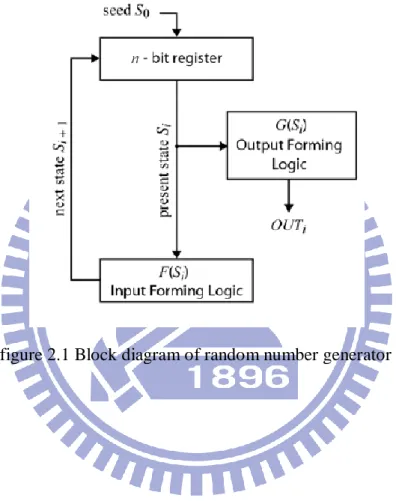
In the last few years, discretized chaotic dynamical systems were also exploited for cryptographic applications, and several works were published on this subject[15]. A digital PRNG is a finite state machine that initialized by an n bit initial seed S0.
18
In figure 2.1, the general structure of a PRNG is shown: the memory block consists on n flip-flop storing the present state Si, the input forming logic defined by logic function F evaluates the next state Si+1, according to the relationship Si+1 = F(Si), the output forming logic defined by the function G decodes the state and determines the current output bit (OUTi=G(Si)).
19
Chapter 3
Proposed RSA Architecture
3.1 Word-based Montgomery Multiplication
Montgomery algorithm computes the modular multiplication without trial division. It turns the modular multiplication into iterations of n-bit addition and shifting and reduces the complexity of modular multiplication to constant time operations. A major design concern for multiplication units used in cryptography is the large number of operand bits, which cause large fanout of signals, large wire delays, and complex routing.
Tenca and Koc proposed a scalable word-based architecture [19] based on radix-2 Montgomery Multiplication. It allows the exploration of several design trade to obtain the best performance in a limited chip area without limiting the operand precision.
Algorithm 3.1 executes a series of operation to generate XYr−1mod N, scanning Y and
N word-by-word and scanning X bit-by-bit. All vecter can be represented as: N = (0,Ne − 1,...,N1,N0),
Y = (0,Ye −1,...,Y1,Y0),
S = (0,Se −1,...,S1,S0),
20
where n is a multiple of word size w, the n-bit operands are split into e words, and e =
n/w. The concatenation of two vectors A and B is represented as (A, B). The bit position i
of the kth word of an operand A is represented as Aki .
Algorithm 3.1. (Word-based Montgomery Multiplication Algorithm)
Input : X,Y ,N Output: S 1. S = 0; 2. for i = 0 to n−1 2.1 (Ca,S0)=xiY0+S0 ; 2.2 if = 1 then; i. (Cb, S0) = S0 + N0 ; ii. for j = 1 to e; A. (Ca, Sj) = Ca + xiYj + Sj ; B. (Cb, Sj) = Cb +Nj +Sj ; C. Sj−1 = ( , ); 2.3 else; i. for j = 1 to e; A. (Ca, Sj) = Ca + xiYj + Sj ; B. Sj−1 = ( , ); 3. return S;
The right-shift operation must wait for the most significant position of Sj−1 of the next
loop. This is a critical limitation of the algorithm. To implement this algorithm, unrolling the for loop to pipelined architecture is a useful skill for increment of parallelism. The dependency on the carry bits within j loop restricts their parallel execution. However, instructions in different i loops may be executed in parallel.
21
3.1.1 Proposed Word-based Montgomery Multiplication
Architecture I
The fundamental problem with Tenca-Koc architecture is the dependency caused by waiting to shift right. We can solve this problem on architecture layer. Every output S of Processing Unit(PU) is w-1 bit because of dependency of right-shift word. The wth bit will be executed at next cycle. We acquire wth bit by forwarding method, which means the wth bit bypass registers. The forwarding bit is represented as:
= (Ca + Cb +oddNj +xiYj + Sj ) mod 2;
Where odd equals S00. If S00 is odd, the summation would include Nj, otherwise there
is no Nj in this summation. Notice that the right part of equal sign are wires in PUi. Left part of equal sign is a wire in PUi+1. It is a combinational circuit, which bypass the registers so it can execute with Sj−iw−1:1 at the same cycle. This method also increase
critical path of PU, so next step is simplifying it. Considering right-shift with S, we can abandon Cb. After right-shift Cb is the wth bit of S, we can directly pass this bit to next PU
so we don‟t need to store it by a register. Second, the operation of “mod 2” also means tell the summation is odd or even. We can use XOR to replace two-level carry save adder. The forwarding bit is represented as:
= Ca odd x ;
Figure 3.1 shows block diagram of forwarding circuits. Arrows are the nets without passing registers.
22
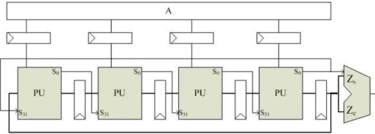
Figure 3.1 Block diagram of proposed word-based Montgomery multiplication I
Figure 3.2 Block diagram of proposed word-based Montgomery multiplication II
3.1.2 Proposed Word-based Montgomery Multiplication
Architecture II
In algorithm 3.1, executing an n-bit multiplication spend n iterations. Considering this
case: if xi is zero and S is even. That means we only to do right-shift without any addition.
Shift is easily to complete by hardware. We can combine right-shift when this case happened in order to reduce n times iteration of multiplier. Algorithm 3.2 is proposed bypass algorithm:
23
Algorithm 3.2. (Proposed Word-based Montgomery Multiplication Algorithm II)
Input : X,Y ,N Output: S
1. S = 0; i = 0; 2. while ( i < n )
2.1 odd=(xiY+S )mod 2;
2.2 case{odd, xi} 2’b00: S’ = S ; 2’b01: S‘ = S + Y; 2’b10: S‘ = S +N; 2’b11: S’ = S +Y + N; endcase 2.3 if (bypass==1) S = S’ / 4; i = i + 2; else S = S’ / 2; i = i + 1; 3. if S>N, then S=S-N; 4. return S;
We want to simplify case {odd,xi} = {0, 0}. If in next iteration we meet previous case, we only to do right-shift. We combine the shift next iteration with this one. Where bypass represented as:
bypass = (S‟.ai+1= = 0).
That means we detect PU computing without addition next cycle. So we could shift 2 bits and jump over i+1th iteration. It also reduces the total multiplication computing time. But
24
this method also produces some problems. First, It increases design complex of delivering xi from memory to PUs. If bypass is active, we will abandon multiplicand ai+1 and get ai+2. Getting x is not in a regular period. Thus, we abandon PUi+1 replace ai+1. Xi+1 is still deliver to PUi+1, but S is passed to PUi+2. So we can also getting x from memory in a regular period. Second problem is that S is not exactly a w-bit value. It represented with two w-bit Ssum and Scarry In order to decrease critical path without w-bit adder in PU. That means when Ssum and Scarry are both even, we can tell S is even. If Ssum and Scarry are both odd, we could not do right-shift because that will delete carry-out bit at LSB. Bypass will represented as:
bypass = (S’sum.S’carry.ai+1= = 0).
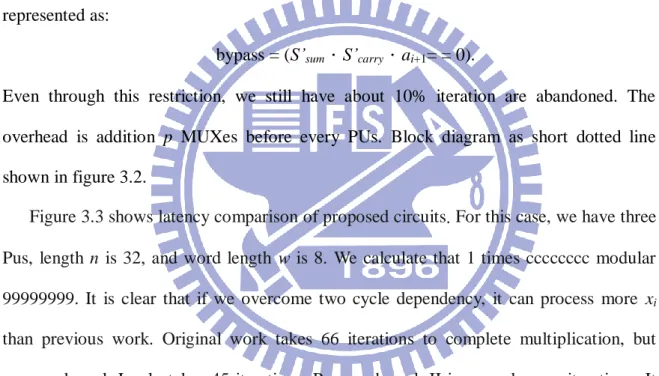
Even through this restriction, we still have about 10% iteration are abandoned. The overhead is addition p MUXes before every PUs. Block diagram as short dotted line shown in figure 3.2.
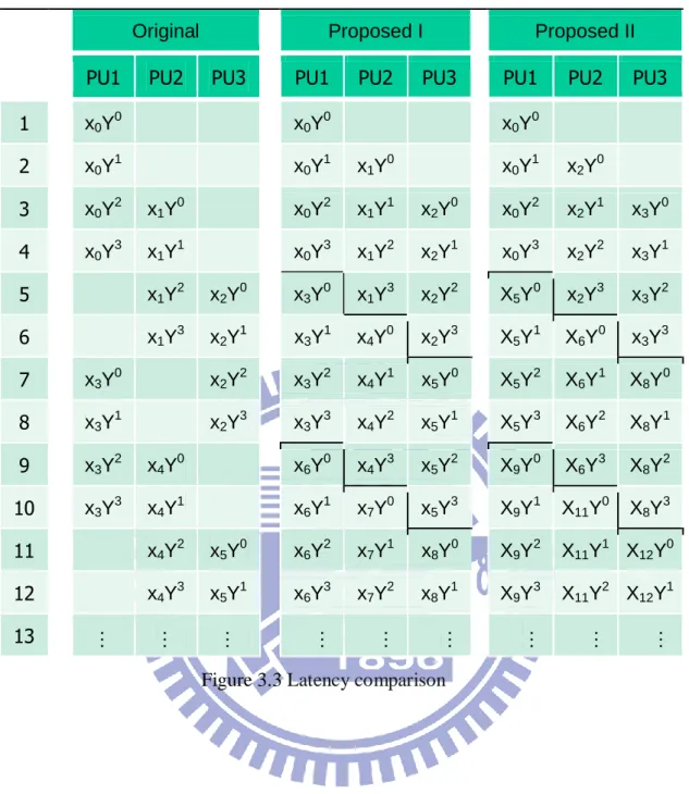
Figure 3.3 shows latency comparison of proposed circuits. For this case, we have three Pus, length n is 32, and word length w is 8. We calculate that 1 times cccccccc modular 99999999. It is clear that if we overcome two cycle dependency, it can process more xi
than previous work. Original work takes 66 iterations to complete multiplication, but proposed work I only takes 45 iterations. Proposed work II ignores dummy iterations. It takes only 32 iterations.
25
Original Proposed I Proposed II
PU1 PU2 PU3 PU1 PU2 PU3 PU1 PU2 PU3
1 x0Y0 x0Y0 x0Y0 2 x0Y1 x0Y1 x1Y0 x0Y1 x2Y0 3 x0Y2 x1Y0 x0Y2 x1Y1 x2Y0 x0Y2 x2Y1 x3Y0 4 x0Y3 x1Y1 x0Y3 x1Y2 x2Y1 x0Y3 x2Y2 x3Y1 5 x1Y2 x2Y0 x3Y0 x1Y3 x2Y2 X5Y0 x2Y3 x3Y2 6 x1Y3 x2Y1 x3Y1 x4Y0 x2Y3 X5Y1 X6Y0 x3Y3 7 x3Y0 x2Y2 x3Y2 x4Y1 x5Y0 X5Y2 X6Y1 X8Y0 8 x3Y1 x2Y3 x3Y3 x4Y2 x5Y1 X5Y3 X6Y2 X8Y1 9 x3Y2 x4Y0 x6Y0 x4Y3 x5Y2 X9Y0 X6Y3 X8Y2 10 x3Y3 x4Y1 x6Y1 x7Y0 x5Y3 X9Y1 X11Y0 X8Y3 11 x4Y2 x5Y0 x6Y2 x7Y1 x8Y0 X9Y2 X11Y1 X12Y0 12 x4Y3 x5Y1 x6Y3 x7Y2 x8Y1 X9Y3 X11Y2 X12Y1 13 … … … …
26
3.2 Architecture of Proposed Montgomery Multiplier
The proposed architecture of the reconfigurable multiplier is presented in this chapter. As mentioned in subsection 3.1, the precision of operands is only limited by the memory size and control subsystems. It is adapted to all precision less than 2048 bits over prime fields. All of main components used in the scalable multiplier are detailed in following subsections.
3.2.1 Processing Unit
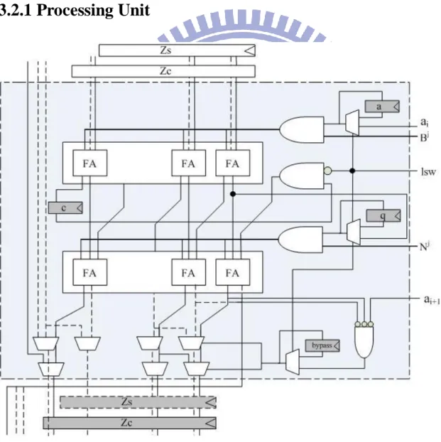
Figure 3.4 Architecture of processing unit
27
adder to do the four-input (Zs, Zc, ai.B, q.N) redundant arithmetic. First carry save adder calculates partial sum of Zs, Zc, and ai.B. The odd parity is determined by the first bit of partial sum when PU processes first word which we call LSW (Least significant word). LSW also determines using original ai or taking ai+1. Last bit of partial sum is stored by the carry-reg. It will be clear when LSW is high.
Output of Zs is 31-bit because of dependency of shift-right word. We will acquire this value by forwarding skill. LSB of two-level CSA sum takes bypass to next PU without passing register. It is the value of 32nd bit of Zs. Although forwarding method increase critical path of PUs, we can easily simplify it. LSB of two-level CSA sum can replace by a five-input XOR gate.
The MUX that below registers select Z or Z divide 2. Value of Z divide 2 is taken from the second PU previous of this one.
3.2.2 Number of Processing Unit Size of Word
The time to compute n bits depends on word number e, word-size w, and number of PUs p. Word number e dominates the kernel cycle (a PU finishes processing one value until next value comes). One PU processes that x times Y spend e cycles. Considering 2-cycle latency because of dependency between Sj and Sj-1, next PU has one cycles stall after previous PU finished. According to early subsection, we used forwarding skill to reduce two-cycle latency. In case, number of words larger than number of PUs, proposed architecture takes e*(e*w/p)+(p-1) cycles finish total multiplication. Tenca-Koc takes 2*e*(e*w/p)+(p-1) cycles . Another case if number of words larger than number of PUs, kernel cycle would not more than p. It is only half of previous work.
28
reduce more redundant iterations. How many iterations are reduced dependent on the number of 0s in intermediate values in data-path. Random sequence generator affects these values, so get key information by observing reduced time is not easy.
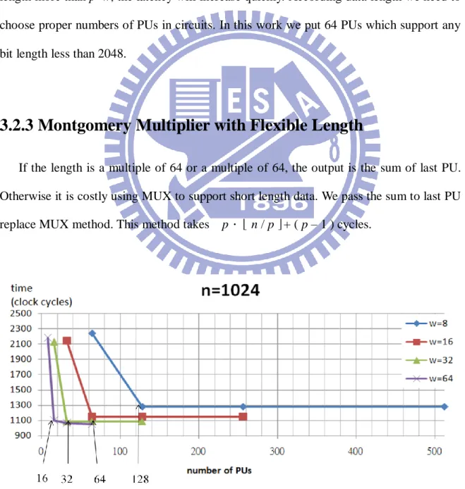
The formula of total Montgomery multiplication time in this work is
e*(e*w/p) + ( p-1 ) for data length > p*w
( e*w ) + ( p–1 ) for data length <=p*w
figure 3.6 shows the relationship between processing time and number of PUs. If data length more than p*w, the latency will increase quickly. According data length we need to choose proper numbers of PUs in circuits. In this work we put 64 PUs which support any bit length less than 2048.
3.2.3 Montgomery Multiplier with Flexible Length
If the length is a multiple of 64 or a multiple of 64, the output is the sum of last PU. Otherwise it is costly using MUX to support short length data. We pass the sum to last PU replace MUX method. This method takes p.⌊ n / p ⌋+ ( p – 1 ) cycles.
29
3.3 Random Bit Generator
3.3.1 Random Bit Generator from Chaotic Map
In 1989, Huertas, Quintana, and Valencia established Chaos discrete maps from digital circuits[16]. As times goes on, Chaotic map had been developed and modified. The PRNG based on the discretization of a chaotic map F is implemented with the input forming logic F(Si) realizing a discretized f ’ of the map f. The map f is defined on a continuous state space I ⊂ R. And f can be approximated with its discretized version f ’. To keep the circuit complexity low, an n-bit fixed-point representation of the discretized state is commonly used with the discretized state x’.
In particular, considering the Chaotic map, defined as:
fs (x) = β ⋅ x mod 1,
where the state space I is the interval [0 1), the discretized state space I’ ⊂ I is assumed in this work to be the set of rational values that can be expressed as
x=(0.b1b2...bn)2 bj ∈{0,1}.
At time i, the fractional part of xi’, ( b1,…, bn ), is stored in the state register as Si. Since different bit strings b1,…, bn identify different discretized states, each xi’ can be unequivocally related to its fractional part, i.e. to a natural number
ki = 2n ⋅xi’ , with 0 ≤ ki ≤ 2n −1.
The generic discretized map fS’ : I’ → I’ has the following expression:
fS’(x’) = [β⋅x’ mod 1]tr ,
30
truncation to the precision 2-n. Accordingly, above equation is equal to
fs’(x’) = ⌊ 2n β⋅x’ mod 2n⋅2-n,
where ⌊x represents the integer part of x. The output forming logic can be represented as:
g(k)=2n fs’ ( k / 2n) = ⌊β⋅k mod 2n.
Moreover, in what follows the finite precision representation of β is taken into account, in particular β is supposed to belong to the set
Β ≡ {q ∈ Q : q = m ⋅ 2 − n ; m ∈ N }.
31
3.3.2 Proposed Dynamic Random Bit Generator
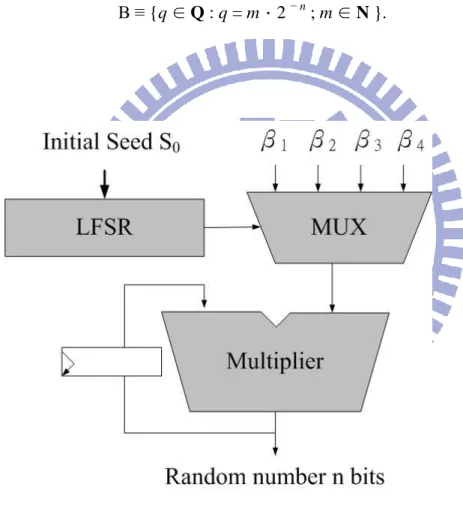
In order to increase the period and rate of passing random sequence test, we have a proposed architecture of RNG of Chaotic map. The fundamental idea is to change dynamically characteristic parameter of chaotic map. According to early subsection, β is a 2n-bit value and taken from set B. As shown in Figure 3.6, where block DCP (Dynamic Characteristic Parameter) includes four different characteristic parameters. The various constants are selected through a decoder driven by a 5 bits LFSR. Obviously, increasing the length of the Liner Feedback Shift Register (LFSR) which drives the decoder makes the period of the overall system increases, but the circuit‟s complexity increases too. Increasing the period also means raise entropy of the random sequence.
As shown in table 3.1, we have four similar β can choose. In order to share resource, any β in the set only has less than two different bits from others. Output forming logic of dynamic chaotic map are represented as:
Out(x) = [ β*.k ] mod 2n,
Where β* means dynamic parameter. Another purpose for this work is to mask β from multi-layer perceptron neural network(MLP-MM). According to statistics
by MLB-MM, it could calculate the parameter we used in circuit in 2n cycle. It would decrease the security of our circuit. There are two methods to solve this problem: one is taking dynamic parameter to mask our true parameter, and another one is taking true random vector as initial seed S0.
32
Table3.1 Four parameters LFSR output Chaos base parameter
00 111…00.11…11
01 011…00.11…11
10 110…00.11…11
11 010…00.11…11
3.4 Proposed RSA Crypto-core with RNG
The modular exponentiation algorithm mentioned in early subsection are three methods: L-R, R-L, and powering ladder. In this work, we choose powering ladder method[28] in order to increase the parallelism and better against SPA and DPA ability.
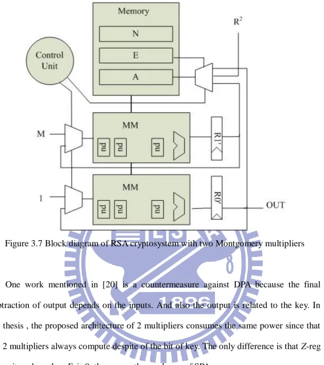
As shown in figure 3.7, we have two sets of multiplier. There are four 2048 bits-bit registers: N for modular, E for key, R2 mod N, and M for plaintext. Register A for storing multiplicand, so R2 store in A at first iteration of multiplication.
The basic security of RSA is based on the difficulty of factoring the product of two primes. But recent research discovered that the information of the key can be estimated by tracing the power consumption. DPA is a powerful tool that allows cryptanalysis to extract secret key and compromise the security of smart cards and other cryptographic devices by analyzing their power consumption. Simple power analysis is a simpler form of the attack that does not require statistical analysis.
33
Figure 3.7 Block diagram of RSA cryptosystem with two Montgomery multipliers
One work mentioned in [20] is a countermeasure against DPA because the final subtraction of output depends on the inputs. And also the output is related to the key. In the thesis , the proposed architecture of 2 multipliers consumes the same power since that the 2 multipliers always compute despite of the bit of key. The only difference is that Z-reg keeps its value when Ei is 0, thus cause the weakness of SPA.
Another work [24] recall the equation Me+rφ(N) ≡ Me (mod n). Where parameter r is
a random number produce by a random number generator. The DPA countermeasure can add r to the original key E as a new key. Therefore, The key guessed by the adversary is randomized thus preventing the ZEMD attack. But this method increase total executing time of modular exponentiation. Take n-bit random number will increase log2n times Montgomery multiplication executing time.
34
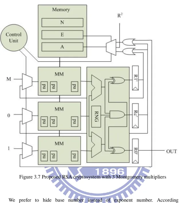
Figure 3.7 Proposed RSA cryptosystem with 3 Montgomery multipliers
We prefer to hide base number instead of exponent number. According to common-multiplicand multiplication[8], two register R0 and R1 can be extract common bit as:
Rcom = (R0 & R1&rand(S0)),
Where rand(S0) is n-bit random sequence. And remainder of R0 and R1 are: R0,c = (R0 Rcom),
R1,c = (R1 Rcom),
It will change two 32-bit registers to three, but we can hide R0 (or R1) to two different number combination. Considering random number in Rcom , this combination has widely
35
chosen. Even if key E has not been hide, it can still preventing the DPA attack because of base number is randomized. Assume this case Ek = 1, follow powering ladder algorithm:
R0←R0.R1
R1←R1.R1 The operation can be replace by this one:
R0← R0,c R1 + RcomR1
R1← R1,c R1 + RcomR1
We can use three Montgomery multiplier to complete this architecture as figure 3.8. The overhead resources are one Montgomery multiplier, one RNG, one register files and some combinational circuits. Because we take Word-base architecture, the extra register and combinational circuits are all 32 bits, not n bits.
36
Chapter 4
Implement Result and Comparison
4.1 RNG Testing
SP800-22[26] is special publication release from National Institute Standards and Technology (NIST). It discusses some aspects of selecting and pseudorandom number generators. Generators use in cryptographic application may need stronger requirements than for other applications. In particular, their outputs must be unpredictable in the absence of knowledge of the inputs.
The NIST test suite[27] is a statistical package consisting of 15 test that developed to test the randomness of binary sequences produced by either hardware or software based cryptographic random or pseudorandom number generators. These tests focus on a variety of different types of non-randomness that could exist in a sequence. Some tests are decomposable into a variety of subtests.
37
Table 4.1: Comparison with RNG passing SP800-22 length Original work[18] Propose work
14 71.9 74.9 15 84.6 87.7 16 94.0 96.9 17 95.7 97.6 18 96.7 98.0 19 97.7 98.7 The 15 tests of SP800-22:
1. The Frequency (Monobit) Test, 2. Frequency Test within a Block, 3. The Runs Test,
4. Tests for the Longest-Run-of-Ones in a Block, 5. The Binary Matrix Rank Test,
6. The Discrete Fourier Transform (Spectral) Test, 7. The Non-overlapping Template Matching Test, 8. The Overlapping Template Matching Test, 9. Maurer's "Universal Statistical" Test, 10. The Linear Complexity Test, 11. The Serial Test,
12. The Approximate Entropy Test, 13. The Cumulative Sums (Cusums) Test, 14. The Random Excursions Test, and 15. The Random Excursions Variant Test.
38
The order of the application of the test in the suite is arbitrary. We try all of input vectors for initial seed and observe how many vectors passing total 15 tests. Passing rate equals vectors of pass over total vectors. Each row of table 4.1 shows the n value and the number of passing rate. Proposed work increases the randomness, which means if we take oscillator or analog to digital device for PRNG input source, there is a higher guarantee for producing random sequence we need.
4.2 Implement with Cell Base Design
Table 4.2: The verification results on ASIC
Design ASIC Technology UMC 90nm Clock frequency 285.7MHz Gate count 467k (3MMs) Key length 1024 2048 4096 Computation time (ms) 3.5 13.7 106.6 Throughput (kb/s) 289.3 149.7 38.42
A word-based RSA scheme is given in this work. This section shows the hardware implementation results. In this thesis, all of the design in hardware is implemented using RTL (Register- Transfer-Level) Verilog HDL (hardware description language) and synthesized on application-specific integrated circuit (ASIC). The technology of ASIC design is using UMC1 90nm CMOS process. The RTL synthesizer uses Synopsys3 Design Compiler for ASIC. The data throughput of RSA is given by
39
The clock frequency is set to 285.7MHz and gatecount is 467k with three Montgomery multipliers. Cycle period is 3.5ns. The cycles of multiplication are about ( n + p)*90% cycles. And The cycles of RSA are about (n+2)*(MM cycles). Where Montgomery method must transport domain between integer and Montgomery domain, So there are two extra MM cycles for transporting. The detail value is shown as table 4.2.
Table 4.3: Comparison with other 1024-bit Modular Multiplier with cell base design
Table 4.3 shows the comparison with other 1024-bit modular multipliers implementations with ASIC design. Our work is not the most outstanding, but our works are scalable designs and [29] is not. Proposed designs can be modify to high radix architecture. The performance would be better than now.
Author [29] [30] Proposed Technology 0.13μ m CMOS 0.13μ m CMOS 90nm CMOS Clock frequency (MHz) 715 781.25 675.68 333.3 Gatecount(k) 105 80 82 115 Throughput (kb/s) 712.22 775.95 663.37 379.26 Note w=64 w=1024 p=257 w=4 p=65 w=16 p=32 w=32
40
Table 4.4: Comparison with other 1024-bit RSA cryptosystem with cell base design
Table 4.4 shows the comparison with other 1024-bit RSA implementations with ASIC design. In contrast to proposed design, the work shows a big area but the throughput is higher. In the nearly future, ROC government will establish 4096 bits RSA for standards. That means high throughput is the first consideration. The area of Mukaida‟s work is much higher than the others, since it is radix-232
and calculates some parameter beforehand. The throughput of proposed work is higher than any others. We add one more Montgomery multiplier to against DPA attack. One Montgomery multiplier‟s gate count is about 130k. And it doesn‟t affect the frequency or throughput. Initial seed of random number generator is given by user.
Author Mukaida [22]
[21] Chen[25] Lin[24] Proposed
Technology 0.18μ m 0.18μ m 0.18μ m 0.18μ m 90nm Methodology CRT Montgomery Montgomery Montgomery
Clock frequency (MHz) 200 235 370 200 285.7 Gatecount(k) 965 2262 138 365 337 467 Throughput (kb/s) 5000 2000 83 162 289.3
Note radix-232 Coprocessor p=16 w=16 p=64 w=32 p=32 w=32 (2MMs) p=32 w=32 (3MMs)
41
Chapter 5
Conclusion
In this thesis, a hardware architecture of word-based scalable RSA cryptosystem in
GF(p) is given. In order to reduce execution time, a Montgomery modular multiplication
algorithm and circuit are proposed. Forwarding circuit solves data dependency hazard of word-based Montgomery multiplication from two cycles to one cycle. Furthermore, bypass algorithm combines redundant shift operation, which shortens latency of processing modular multiplication about 90% of original work. The total cycles of processing multiplication once are about n*90%+(n/p). Proposed Montgomery multiplier architecture is applied in RSA or ECC cryptosystem. This work can be modified to support binary field GF(2n) operation by simply eliminating the carry.
On the other hand, we modify random number generator based on Chaotic map. Higher passing rate RNG may suite for cryptosystem application. The total RSA architecture includes three MMs and one RNG, it against SPA and DPA without extra multiplication. The total cycles of processing modular exponentiation are n+2 times MM processing cycles. According to implementation result, it is synthesized using 90nm CMOS technology with 467k gates. The clock period is 3.5 ns.
42
Bibliography
[1] W. Diffie and M. E. Hellman, “New directions in cryptography,” IEEE Transactions
on Information Theory, vol. IT-22, no. 6, pp. 644-654,1976.
[2] R. L. Rivest, A. Shamir, and L. Adleman, “A method for obtaining digital signatures and public-key cryptosystems,” Commun. ACM, vol. 21, no. 2, pp. 120–126, 1978. [3] T. E. Gamal, “A public key cryptosystem and a signature scheme based on discrete
alogarithms,” in Proceedings of CRYPTO 84 on Advances in cryptology. New York, NY, USA: Springer-Verlag New York, Inc., 1985, pp. 10–18.
[4] PKCS#1: RSA Cryptography, RSA Laboratories Std. 800-57, 2002.
[5] Digital Signatures Using Reversible Public Key Cryptography for the Financial
Services Industry - RSA digital signature technique, ANSI Std. X9.31, 1998.
[6] K. Koc, “High-speed RSA implementation,” tech. rep., RSA Laboratories, 1994. [7] M. Joye, and S-M. Yen, “The Montgomery Powering Ladder”, CHES 2002, LNCS
2523, pp. 291–302, Springer-Verlag, 2003
[8] Sung-Ming Yen and Chi-Sung Laih. Common-multiplicand multiplication and its application to public-key cryptography. Electronics Letters, 29(17):1583–1584, August 1993v
[9] P. Kocher, “Timing attacks on implementations of diffie-hellman, rsa, dss, and other systems,” in Proceedings of Advances in Cryptology-CRYPTO ’96. Springer-Verlag, 1996, pp. 104–113.
43
related attacks,” in http://www.cryptography.com/dpa/technical, 1998.
[11] T. S. Messerges, E. A. Dabbish, and R. H. Sloan, “Power analysis attacks of modular exponentiation in smartcards,” in Proceedings of Workshop on
Cryptographic Hardware and Embedded Systems. Springer-Verlag, August 1999,
pp. 144–157.
[12] S. Tezuka, Uniform random numbers: theory and practice, Kluwer Academic Publishers, 1995
[13] R. David, Random Testing of Digital Circuits: Theory and Application, Dekker Inc., New York, 1998.
[14] Intel Platform Security Division, “The Intel Random Number Generator”, Intel Corporation, 1999.
[15] M. Jessa, “The period of Sequences Generated by Teni-Like Maps,” IEEE Trans. On CAS-part I, vol. 49, no. 1, Jan 2002.
[16] J. Huertas, J. Quintana, M. Valencia, “Chaos from Digital Circuits: Discrete Maps,” Int. Symp. on Networks, Systems and Signal Processing, pp. 391-395, Zagreb, 1989.
[17] R. Mita, G. Palumbo, S. Pennisi, M. Poli, “A Novel Pseudo Random Bit Generator for Cryptography Applications,” ICECS 2001, pp. 489-492, Dubrovnik (croatia),
September 2002.
[18] T. Addabbo, M. Alioto, A. Fort, S. Rocchi, V. Vignoli, “Long Period Pseudo Random Bit Generators Derived from a Discretized Chaotic Maps” Circuits and Systems, 2005. ISCAS 2005. IEEE International Symposium on, Vol. 2, pp 892- 895, 2005.
[19] A. F. Tenca and C¸ etin Kaya Ko¸c, “A scalable architecture for modular multiplication based on Montgomery‟s algorithm,” IEEE Transactions on
44
[20] C. D. Walter, “Precise bounds for montgomery modular multiplication and some potentially insecure rsa moduli,” in Topics in Cryptology-CT-RSA 2002, B.
reneel (editor), Lecture Notes in Computer Science, vol. 2271. San Jose, CA, USA:
Springer Berlin / Heidelberg, 2002, pp. 30–39.
[21] Haixin Wang, Guoqiang Bai, and Hongyi Chen, “Zodiac: System Architecture Implementation for a High-Performance Network Security Processor”, 19th IEEE International Conference on Application-Specific Systems, Architectures and Processors, Leuven BELGIUM, JUL 02-04, 2008, pp. 91-96.
[22] K. Mukaida, M. Takenaka, N. Torii, and S. Masui, “Design of high-speed and areaefficient montgomery modular multiplier for rsa algorithm,” in IEEE Symp.
VLSI Circuits, 2004, pp. 320–323.
[23] C. P. Su, C. H. Wang, K. L. Cheng, C. T. Huang, and C. W. Wu, “Design and test of a scalable security processor,” in Proc. Asia and South Parific Design
Automation Conf. (ASP-DAC), vol. 1, pp. 372-375, Jan 2005.
[24] Y.-C. Lin, “A RSA Crypto-core Baesd on Scalable Montgomery Multiplication with DPA and SPA Resistance,” Master‟s thesis, National Chiao Tung University, 2008. [25] Y.-L. Chen, “Design and implementation of reconfigurable rsa cryptosystems,”
Master‟s thesis, National Chiao Tung University, 2006.
[26] SP800-22, “A Statistical Test Suite for Random and Pseudorandom Number Generators for Cryptographic Applications,” U.S. Department of commerce,
NIST, 2008.
[27] http://csrc.nist.gov/groups/ST/toolkit/rng/documentation_software.html
[28] Sung-Ming Yen and Chi-Sung Laih, "Fast Algorithms for the LUC Digital Signature Computation," IEE Proceedings: Computers and Digital Techniques, Vol.142, No.2, pp.165-169, March 1995.
45
[29] M. D. Shieh, J. H. Chen, H. H. Wu, and W. C. Lin, “A new modular exponentiation architecture for efficient design of rsa cryptosystem,” IEEE Transactions on Very Large Scale Integration (VLSI) Systems archive, vol. 16, no. 9, pp. 1151–1161, September 2008.
[30] M. D. Shieh, and W. C. Lin, “Word-Based Montgomery Modular Multiplication Algorithm for Low-Latency Scalable Architectures,” IEEE Transactions on Computers, vol. 59, no. 8, pp. 1145–1151, August 2010.
46