國
立
交
通
大
學
資訊科學與工程研究所
碩
士
論
文
兩階段比例:一個綜合 802.16e-2005 媒體
存 取 層 的 上 行 和 下 行 頻 寬 分 配 演 算 法
Two-Phase Proportionating (TPP): A Combined Uplink
and Downlink Bandwidth Allocation Algorithm for
802.16e-2005 MAC
研 究 生:簡世昕
指導教授:林盈達 教授
兩 階 段 比 例 : 一 個 綜 合
8 0 2 . 1 6 e - 2 0 0 5
媒 體 存 取 層 的 上 行 和 下 行 頻 寬 分 配 演 算 法
Two-Phase Proportionating (TPP): A Combined Uplink and Downlink
Bandwidth Allocation Algorithm for 802.16e-2005 MAC
研 究 生:簡世昕 Student:Shih-Hsin Chien
指導教授:林盈達 Advisor:Ying-Dar Lin
國 立 交 通 大 學
資 訊 科 學 與 工 程 研 究 所
碩 士 論 文
A ThesisSubmitted to Institute of Computer Science and Engineering College of Computer Science
National Chiao Tung University in partial Fulfillment of the Requirements
for the Degree of Master
in
Computer Science
June 2006
Hsinchu, Taiwan, Republic of China
兩階段比例: 一個綜合 802.16e-2005
媒體存取層的上行和下行頻寬分配演算法
學生: 簡世昕
指導教授: 林盈達
國立交通大學資訊科學與工程研究所
摘要
IEEE 802.16e-2005 宣稱可為無線都會型網路支援高頻寬傳輸。然而通道的 品質非常容易受到長距離、不穩定的無線環境而降低,造成對及時應用程式的損 害。因此,一個合適可行的頻寬分配演算法來充份利用可使用的頻寬並提供差別 式服務是有所需要的。在本論文中提出了一個兩階段比例演算法來解決上述的問 題。在第一階段中,根據用戶台所發出的頻寬要求去動態決定上下行的次訊框, 同時考慮上下行不同的時槽大小。在第兩階段中,則是利用累加的最大可支援速 率當作權重和一新穎的調整係數用來增加權重給頻寬要求較多的佇列,來進一步 去差別各個服務等級。實驗模擬結果証實兩階段比例在頻寬利用上比靜態分配改 善了 20%的效率,並且仍能嚴格地保證差別式服務。此外,針對和其它方法的效 能比較,顯示兩階段比例在頻寬利用率和差別式服務上來的較好。 關鍵字: 頻寬分配,802.16e-2005,媒體存取層,服務品質Two-Phase Proportionating (TPP):
A Combined Uplink and Downlink
Bandwidth Allocation Algorithm for 802.16e-2005 MAC
Student:
Shih-Hsin
Chien
Advisor:
Dr.
Ying-Dar
Lin
Department of Computer Science and Engineering
National Chiao Tung University
Abstract
The IEEE 802.16e-2005 claims to support high bandwidth for the wireless metropolitan area network. However, the link quality is very likely to degrade due to the long-distance and unstable wireless link, bringing ordeals to the real-time applications. Therefore, a feasible bandwidth allocation algorithm is required to utilize the precious bandwidth and to provide service differentiation. This work proposes a Two-Phase Proportionating (TPP) algorithm to tackle the above challenges. Considering different slot sizes for the uplink and downlink whose ratio is 3:2, the first phase dynamically determines the subframe sizes according to the bandwidth requests from subscriber stations. The second phase further differentiates a service class along with a weight which denotes the accumulated maximum sustained rates and with a novel adjustment factor practically reflecting the bandwidth demand of the service class. The simulation results demonstrate that the TPP improves the bandwidth utilization by 20% compared to the static allocation, and the service differentiation are strictly guaranteed. Besides, the performance comparison with other schemes shows TPP has the highest bandwidth utilization and most differentiated for every service class.
Contents
CHAPTER 1 INTRODUCTION...1
CHAPTER 2 BACKGROUND ...4
2.1OVERVIEW OF THE MACPROTOCOL...4
2.1.1 TDD Subframe ...4
2.1.2 Uplink scheduling service classes...5
2.1.3 Detailed Packet Flow in the MAC Layer ...6
2.2RELATED WORKS...7
2.3RESEARCH GOALS...8
CHAPTER 3 TWO-PHASE PROPORTIONATING ...9
3.1OVERVIEW OF THE ALGORITHM...9
3.2DETAILED OPERATIONS OF TPP ...10
3.2.1 Bandwidth Translation and Slot Dispatching ...10
3.2.2 First Phase: Dividing a Frame into Downlink and Uplink Subframes ...11
3.2.2 Second Phase: Dividing Each Subframe for Queues ...12
3.2.3 Per-SS Bandwidth Grant within Each Queue ...13
3.2.4 Example ...15
CHAPTER 4 SIMULATION RESULT...17
4.1SIMULATION ENVIRONMENT...17
4.2NUMERICAL RESULT...18
CHAPTER 5 CONCLUSIONS AND FUTURE WORKS ...25
List of Figures
FIG.1TDD SUBFRAME STRUCTURE. ...4
FIG.2UPLINK/DOWNLINK PACKET FLOW IN THE BSMAC...7
FIG.3ARCHITECTURE OF THE TWO-PHASE PROPORTIONATING (TPP). ...10
FIG.4THE PLACEMENT OF THE SEPARATOR IN THE FIRST PHASE...11
FIG.5PSEUDOCODE OF TPP...14
FIG.6SIMULATION TOPOLOGY FOR 1BS WITH 16SSS AND REMOTE STATIONS...17
FIG.7EFFECTIVENESS OF THE FIRST PHASE PROPORTIONATING.THE TRAFFIC LOAD RATIO FOR DOWNLINK AND UPLINK IS 3:1. ...19
FIG.8EFFECTIVENESS OF USING A-FACTOR.FOUR SCHEMES WITH SIMPLE WEIGHTS ARE INVOLVED FOR COMPARISON. ...20
FIG.9SERVICE DIFFERENTIATION. ...22
List of Tables
TABLE 1CHARACTERISTICS OF THE SCHEDULING SERVICE CLASSES...5
TABLE 2EXAMPLE OF TPP...15
Chapter 1 Introduction
General broadband technologies have been used to provide multimedia applications with stable connectivity. However, for a growing volume of hand-held devices running these applications, those technologies are unable to meet the requirements such as ubiquitous access, low deployment cost, and mobility support. Broadband wireless access (BWA), standardized as 802.16e-20051 [1] and known as WiMAX, has emerged to be a potential candidate to meet these requirements. The standard defines signaling mechanisms [2] between base stations (BSs) and subscriber stations (SSs) considering both fixed and mobile wireless broadband. It supports not only seamless handover even at vehicle speeds but also an extra service class than the previous version, 802.16-2004 [3].
However, the nature of wireless communication makes it difficult to provide stable signal quality, and could lead to bandwidth less than expected. For example, signal gradually fades as the transmitted distance stretches; channels are usually interfered by others. Rather, though 802.16 defines service classes for differentiation, it does not specify any allocation algorithm to fulfill QoS guarantees. Therefore, a feasible algorithm is required to well utilize and fairly allocate the bandwidth along with the following considerations. First, the Grant Per SS (GPSS) scheme specified in the standard needs to be adhered to. In this scheme, the BS grants requested bandwidth to each SS rather than to each connection, so that the SS can flexibly respond to different QoS requirements of connections. Second, in order to make the best use of a channel, the separation between uplink and downlink subframes and how many slots of physical layer are needed to translate from required bytes, have to be
1
carefully arranged.
Similar situations to design allocation algorithm in 802.16 can be seen in protocols such as Wi-Fi [4] and DOCSIS [5] because of the similar point-to-multipoint system architectures. However, Wi-Fi adopts arbitrary contention for transmission opportunities in any time and is thus not appropriate in the WiMAX environment having lengthy round-trip delay. Furthermore, DOCSIS uses the Grant
Per Connection (GPC) scheme [6], which is not flexible for SSs to be adaptive to
connections of real-time applications and is not supported by the standard. Several works [7-10] regarding allocation algorithms over 802.16 are proposed, but again only the GPC scheme is supported. The solution researched by [11] is based on GPSS, but the separation of the uplink and downlink channels is fixed so that bandwidth is usually not properly utilized.
In this work, a novel bandwidth allocation algorithm, Two-Phase
Proportionating (TPP), is proposed to maximize the bandwidth utilization as well as
to meet the QoS requirements under the Time Division Duplexing (TDD) mode. TDD, compared to the Frequency Division Duplexing (FDD), is frequently favored because of the flexibility to divide a time frame into adequate uplink and downlink subframes and thus avoid bandwidth waste. The algorithm consists of four steps: (1) translating data bytes of requests to sizes of physical layer slots and adding the slots to the corresponding scheduling queues; (2) first proportion to determine the separation between the uplink and downlink subframe; (3) secondary proportion to allocate each subframe to queues of different service classes, and (4) allocating slots in each queue to SSs.
The rest of this work is organized as follows. Chapter 2 briefs the IEEE 802.16 MAC and reviews related works to justify our problems. In chapter 3, we propose the TPP algorithm and illustrate the detailed operations with an example. Chapter 4
presents the simulation environment and results. Finally, chapter 5 concludes this work with some future directions.
Chapter 2 Background
Unlike Wi-Fi which is used for small range communications, WiMAX is mainly applied to metropolitan area networks and therefore must master all data transmission decisions to/from SSs to avoid synchronization problems. In this section, we brief the WiMAX frame structure under TDD mode, describe the five service classes whose connections fill up the frame, and elaborate the detailed packet flow in the BS MAC. According to the flow the bandwidth allocation module as well as its input and output is identified. Some related works investigating the allocation problem are discussed, leading to the statement of the research goals.
2.1 Overview of the MAC Protocol
2.1.1 TDD Subframe Co ntrol messa ges Subchan nel Sepa rator (initial pla c em ent) x S x DR UR 3 2 3 2 1 − − + = Sepa rato r (f ina l placeme nt)
Fig. 1 TDD subframe structure.
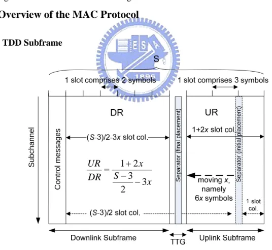
As shown in Fig. 1, the frame structure under TDD includes (1) UL-MAP and DL-MAP for control messages, and (2) downlink and uplink data bursts whose scheduled time is determined by the bandwidth allocation algorithm and is indicated
in the MAP messages. All UL-MAP/DL-MAP and bursts are composed of a number of OFDMA (Orthogonal Frequency Division Multiplexing Access) slots, in which a slot is one subchannel by two OFDMA symbols in uplink and one subchannel by three OFDMA symbols in downlink. This mode is named PUSC (Partial Usage of Subchannels), the mandatory mode in 802.16, and is considered throughout the work.
2.1.2 Uplink scheduling service classes
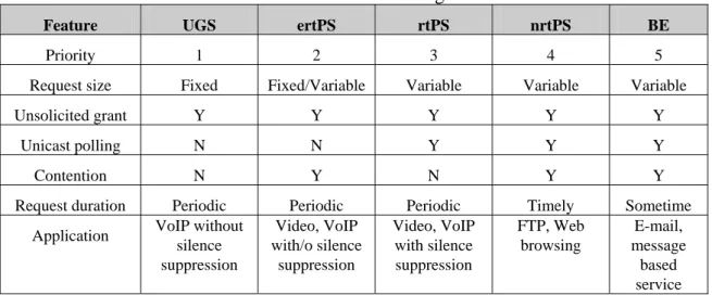
Table 1 summarizes the characteristics of the supported service classes, namely the Unsolicited Grant Service (UGS), Real-time Polling Service (rtPS), Non-real-time polling Service (nrtPS), Best Effort (BE), and the lately proposed Extended Real-time Polling Service (ertPS). Each service class defines different data handling mechanisms to fulfill service differentiation. The UGS has the highest priority and reserves a fixed number of transmission slots at each interval for bandwidth guarantee. rtPS, nrtPS, and BE rely on the periodic polling to gain transmission opportunities from BS, while the ertPS reserves a fixed number of slots as UGS does, and notifies the BS in the contention period for possible request size changes. nrtPS and BE also contend for transmission opportunities if they fail to get enough bandwidth from polling.
Table 1 Characteristics of the scheduling service classes.
Feature UGS ertPS rtPS nrtPS BE
Priority 1 2 3 4 5
Request size Fixed Fixed/Variable Variable Variable Variable
Unsolicited grant Y Y Y Y Y
Unicast polling N N Y Y Y
Contention N Y N Y Y
Request duration Periodic Periodic Periodic Timely Sometime
Application VoIP without
silence suppression Video, VoIP with/o silence suppression Video, VoIP with silence suppression FTP, Web browsing E-mail, message based service
2.1.3 Detailed Packet Flow in the MAC Layer
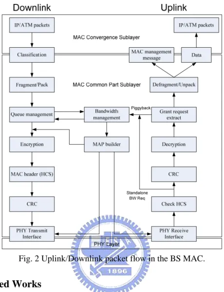
The complete packet flow in the uplink and downlink of a BS MAC is shown in Fig. 2. For the downlink processing flow, both IP and ATM packets from network layer are transformed from/to the MAC Convergence Sublayer (CS) by en/de-capsulating the MAC header. According to the addresses and ports, packets are classified to the corresponding connection ID of a service flow which further determines the QoS parameters. Fragmentation and packing are then performed to form a basic MAC Protocol Data Unit (PDU), whose size frequently adapts to the channel quality, followed by the dispatching of resulting packets into queues. Once the scheduler starts, the bandwidth management unit arranges the data burst transmissions to fill up the frame. The MAP builder then writes the arrangement, namely the allocation results, into the MAP message to notify the PHY interface when to send/receive the scheduled data in the time frame. Encryption, header checksum and frame CRC calculations are carried out to the packets before they are finally sent to the PHY. The uplink processing flow is similar to that of the downlink except the BS receives bandwidth requests which could be either standalone or piggybacked ones. Among the above operations, it is obvious that the bandwidth management, and thus the bandwidth allocation algorithm, are critical and need to be carefully designed in order to improve the performance of the system.
Fig. 2 Uplink/Downlink packet flow in the BS MAC.
2.2 Related Works
A number of works regarding the bandwidth allocation over 802.16 can be found. Hawa and Petr [7] propose a QoS architecture applicable for both DOCSIS and 802.16 and use semi-preemptive priority for scheduling UGS traffic while priority-enhanced WFQ for others. Chu et al. [8] employ the Multi-class Priority Fair
Queuing (MPFQ) for the SS scheduler and the Weighted Round Robin (WRR) for that
of the BS. Though innovative in the architectural design, both of them do not present experiment results validating the architecture. Wongthavarawat and Ganz [9] introduce the Uplink Packet Scheduling (UPS) for service differentiation. It applies the Strict Priority to the selection among service classes, and each service class adopts a certain scheduling algorithm for queues within it. However, this scheme deals with only uplink channel so that overall bandwidth utilization suffers. The Deficient Fair
Priority Queue (DFPQ) [10], which uses the maximum sustained rate as the deficit
counter to specify the transmission quantum, dynamically adjusts the uplink and downlink proportion. Nonetheless, this method is suitable only for GPC rather than GPSS. Maheshwari et al. [11] support GPSS using proportion, though it is not alterable in run-time. Furthermore, the above schemes do not consider the PHY attribute when translating data bytes requested by SSs into OFDMA slots to practically determine the allocation of a time frame.
2.3 Research goals
To solve this problem which could lead to long latency and serious jittering, a well-designed bandwidth allocation algorithm shall possess three merits. First and obviously, the algorithm must implement GPSS to comply with the standard as well as to provide flexible packet scheduling in SSs. Second, service classes should adhere to the corresponding QoS requirements such as Maximum Sustained Traffic Rate (MSTR) and Minimum Reserved Traffic Rate (MRTR) for differentiated guarantees. The former prevents a certain class from consuming too much bandwidth while the latter maintains a service class with least feeds. Third, in order to achieve high throughput, the proportion of the uplink and downlink subframes should be able to be dynamically adjusted. The separator was previously fixed and failed to adapt to situations in which uplink and downlink bandwidth needs vary.
Chapter 3 Two-Phase Proportionating
This chapter details the concept and procedure of the proposed Two-Phase
Proportionating (TPP) algorithm. Each phase manipulates different levels of
allocation to achieve high bandwidth utilization and QoS guarantees. An example is presented finally.
3.1 Overview of the Algorithm
The goal of bandwidth allocation in 802.16 is actually to fill up the whole TDD time frame, in which the proportions of the uplink and downlink subframes can be dynamically adjusted. Every subframe is further allocated to service queues of different QoS requirements. Observing these two characteristics, the Two-Phase
Proportionating (TPP) is proposed in this work to well utilize the bandwidth. The first
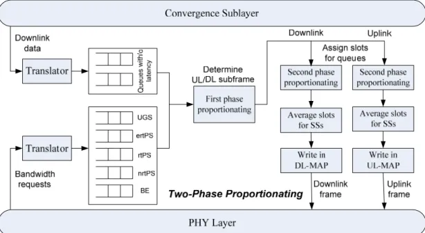
phase decides the subframe sizes according to the requested sizes of both downlink and uplink, while the second phase distributes the bandwidth to each queue based on the corresponding QoS parameter represented as weight, and an adjustment factor reflecting the practical demand. Finally the TPP adheres to the GPSS by granting SSs the allocated bandwidth of each queue. The operations of the algorithm are depicted in Fig. 3 and elaborated in the following subsections.
Fig. 3 Architecture of the Two-Phase Proportionating (TPP).
3.2 Detailed Operations of TPP
3.2.1 Bandwidth Translation and Slot Dispatching
A service flow in an SS issues a bandwidth request whenever necessary. After the BS receives the data traffic from the backbone network and the uplink bandwidth requests from SSs, the TPP translates them from data bytes into the OFDMA slots, which are the basic transmission unit in PHY. This can be done by dividing the data bytes by the OFDMA slot size,
Size Slot OFDMA Bytes Data Slots OFDMA of _ _ _ _ _ _ # = ,
where the OFDMA slot size is derived by multiplying the number of bits that can be depended on the coding rate of SS encoded over a subchannel by the number of symbols in a slot, namely
slot per symbols subchannel per bits Size Slot OFDMA_ _ = _ _ × _ _ .
Notably the number of symbols in a slot is three for UL while two in DL, and the data bytes should include the size of requested bandwidth from a SS, size of the MAC headers, and PHY overhead such as the Forward Error Correction (FEC), preamble,
and guardtime.
These slots are then dispatched to the corresponding service queues comprising the five uplink classes as well as the two downlink classes with/o the latency guarantee. Each queue employs three variables, bandwidth requested slots (BRQ),
Rmax, and Rmin, to accumulate the requested slots, MSTR and MRTR, which are
translated from data rate to number of slots per frame duration, of the service flows. When the total accumulated Rmin is larger than the capacity of frame, TPP denies serving the bandwidth requesting.
3.2.2 First Phase: Dividing a Frame into Downlink and Uplink Subframes
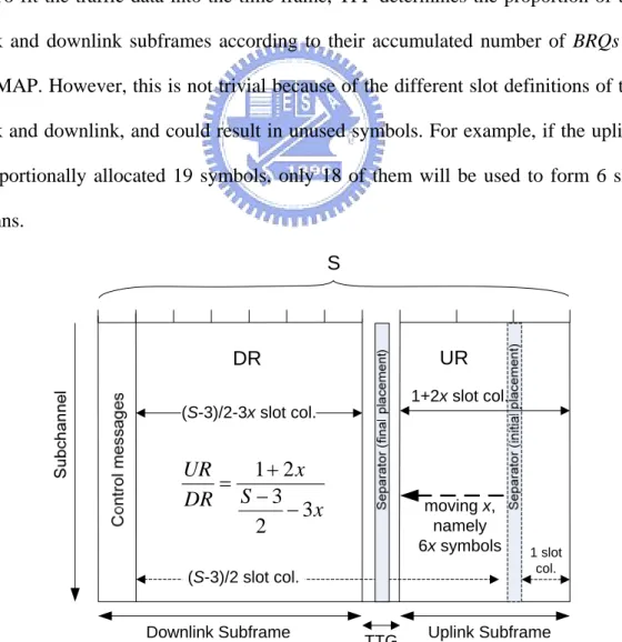
To fit the traffic data into the time frame, TPP determines the proportion of the uplink and downlink subframes according to their accumulated number of BRQs in each MAP. However, this is not trivial because of the different slot definitions of the uplink and downlink, and could result in unused symbols. For example, if the uplink is proportionally allocated 19 symbols, only 18 of them will be used to form 6 slot columns.
Downlink Subframe Uplink Subframe
TTG DR UR S moving x, namely 6x symbols (S-3)/2-3x slot col. 1+2x slot col. x S x DR UR 3 2 3 2 1 − −+ = 1 slot col. (S-3)/2 slot col.
This problem is solved as follows. Depicted in Fig. 4, the most appropriate placement of the separator dividing uplink and downlink subframes is assumed to be x steps from the right, in which one step is considered 6 symbols, the least common
multiple of the uplink and downlink slots. This is to ensure that all symbols are used
up after the division. Two cases need to be discussed here, namely when S, the number of symbols in a frame, is odd and when S is even. If S is odd, the scheme starts with an initial condition in which a slot column exists in the uplink subframe so that the number of remained symbols, S-3, can be divided by 2 in the downlink, leaving no unused symbols. Then the separator moves x steps toward left, which is supposed to be the correct position, resulting in 1+2x slot columns for the uplink
and S 3x
23 − −
slot columns in the downlink, whose ratio should be the same as the ratio of the uplink and downlink requested slots,
x S x DR UR 3 2 3 2 1 − − + = , (1)
where UR and DR represents the total BRQs of the uplink and downlink, respectively. Similar concept can be applied to the case when S is even, except that in the initial condition no slot column exists in the uplink whereas S 2 slot columns are derived in the downlink, x S x DR UR 3 2 2 − = , (2)
The x can be obtained after solving the equation and notably is rounded off if it has a fraction.
3.2.2 Second Phase: Dividing Each Subframe for Queues
After properly dividing the frame into uplink and downlink subframes, we start to allocate them to service queues, respectively, in the second phase. In this phase, the
Rmin of all queues are firstly satisfied for minimum slots guarantee, followed by the
proportionating of the remaining slots to queues except the UGS and ertPS whose requested slots are already served. Since higher service classes typically have higher
Rmax values, we take the Rmax as the weight for proportion. However, that only
referring to Rmax may cause bandwidth waste or starvation of some queues. An
example for the former case is a high class queue having a BRQ very close to Rmin.
The additional number of slots assigned will be more than that of other queues because of the large Rmax, leading to unnecessary bandwidth waste. Similarly, a low
class queue yet having a BRQ close to Rmax may not get enough feed. We use an
adjustment factor, min max min R R R BRQ − −
referred to as A-Factor, for the Rmax of each queue to
fix this problem so that a high class queue requiring less bandwidth (BRQ) will be reflected while a low class queue demanding much will be compensated. The remaining slots are therefore allocated according to the following proportion
min max min min max min min max min : : BE BE BE BE nrtps nrtPS nrtps nrtPS rtPS rtPS rtPS rtPS R R R BRQ R R R BRQ R R R BRQ − − − − − − , (3)
3.2.3 Per-SS Bandwidth Grant within Each Queue
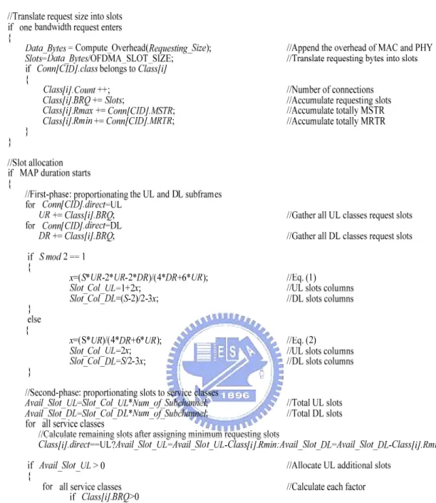
The slots allocated to each queue are further distributed to SSs in the fashion of GPSS. Similar to the second phase, the minimum number of requested slots of each SS is satisfied first. Nevertheless, the remaining slots of each queue are evenly assigned to SSs since there is no priority among them. The pseudocode for the whole procedure is described in Fig. 5 and exemplified in the next subsection.
3.2.4 Example
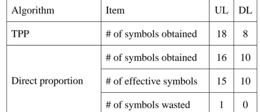
This section elaborates an example of the TPP, in which the parameters and results of the first and second phases are depicted in Table 2(a) and 2(b), respectively. Suppose S is 26, then the separator should be moved toward left with number of steps
x=3 according to Eq. (1), indicating 6x/3=6 slot columns for uplink
while(26− x6 )/2=4 slot columns for downlink. If we use direct proportion,
however, the number of symbols for uplink is 16
40 60 60 26 ≅ + × , in which only 15
symbols are effective.
The uplink is adopted as an example for the second phase. The number of subchannels in a symbol is assumed to be 6 and therefore 6×6=36 slots are allocated to the uplink after the first phase. Rmin, BRQ, and Rmax of the five service
classes are as in Table 2(b). The scheduler allocates the guaranteed minimum number of slots to each queue, and later proportionate the remaining slots to queues of the lower three classes according to Eq. (2) since the UGS and ertPS are already satisfied. As we can see in the table, A-Factor to meet the amount of the requested slots for decreasing the starvation occurrence of low service class and avoiding granting to non demanding service class such as rtPS.
Table 2 Example of TPP.
2(a) Parameters and allocation results of the first phase; UR=60 and DR=40.
Algorithm Item UL DL TPP # of symbols obtained 18 8 # of symbols obtained 16 10 # of effective symbols 15 10 Direct proportion # of symbols wasted 1 0
2(b) Parameters and allocation results of the second phase.
Item UGS ertPS rtPS nrtPS BE
Rmax 8 8 16 8 12
BRQ 8 8 6 8 12
Rmin 8 8 6 4 2
BRQ- Rmin 0 4 10
Rmax with A-Factor 0 2 6
Chapter 4 Simulation Result
Through OPNET simulation we evaluate the TPP algorithm, focusing on the bandwidth utilization and the differentiated guarantee among service classes.
4.1 Simulation Environment
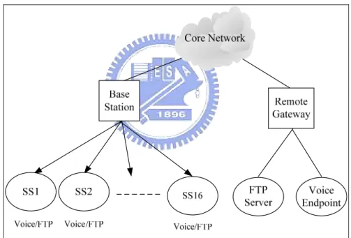
The simulation is implemented based on the DOCSIS module of OPNET. As depicted in Fig. 6, the topology consists of one BS serving 16 SSs, and two remote stations including an FTP server and a voice endpoint. Five service classes are supported and each class involves four SSs.
Fig. 6 Simulation topology for 1 BS with 16 SSs and remote stations.
Table 3(a) summarizes the parameters of the simulation while Table 3(b) defines specific QoS parameters that comprise the number of maximum supported slots and minimum guaranteed slots for each request in different service classes. The total number of slots can be derived as
size slot time MAP rate data num slots _ 8 _ _ _ × × = . (4)
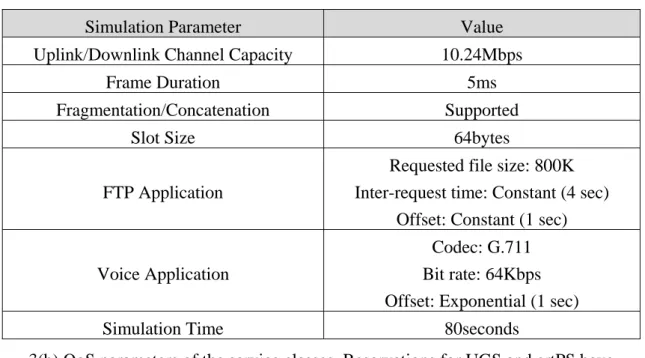
Table 3 Simulation parameters. 3(a) Traffic parameters.
Simulation Parameter Value
Uplink/Downlink Channel Capacity 10.24Mbps
Frame Duration 5ms
Fragmentation/Concatenation Supported
Slot Size 64bytes
FTP Application
Requested file size: 800K Inter-request time: Constant (4 sec)
Offset: Constant (1 sec)
Voice Application
Codec: G.711 Bit rate: 64Kbps Offset: Exponential (1 sec)
Simulation Time 80seconds
3(b) QoS parameters of the service classes. Reservations for UGS and ertPS have been previously made.
Service class UGS ertPS rtPS nrtPS BE
MSTR (slots) N/A N/A 8 6 4
MRTR (slots) N/A N/A 4 2 1
4.2 Numerical Result
Subframe Allocation: Static vs. Dynamic
The first-phase of TPP is advantageous in utilizing the bandwidth when the load of the uplink and downlink are different, as Fig. 7 proves. The FTP traffic load of the downlink is three times of the uplink, and in Fig. 7(a) the downlink utilization is bound to 50% because of the static subframe allocation. However, by stealing the unused uplink slot columns for the downlink, TPP improves the overall link utilization from 75% to 96%. The comparison between static and dynamic allocation of other traffic load ratios is shown in Fig. 7(c).
0 10 20 30 40 50 60 70 80 90 100 0 10 20 30 40 50 60 70 80 Time (sec) B an d iw id th u tiliz at io n ( %
) Total Downlink Uplink
(a) Static subframe allocation. UL:DL = 1:1.
0 10 20 30 40 50 60 70 80 90 100 0 10 20 30 40 50 60 70 80 Time (sec) B andw id th ut il iz at ion ( % ).
Total Downlink Uplink
(b) Dynamic subframe allocation under the traffic load ratio 3:1 for downlink and uplink.
Ratio (Downlink/Total) Static Dynamic
50% 80% 84%
75% 71% 95%
100% 59% 90%
(c) Different traffic load ratio for static and dynamic allocation. Fig. 7 Effectiveness of the first phase proportionating.
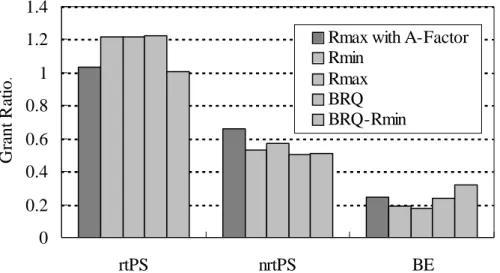
Effectiveness of the A-Factor
As introduced previously, the A-Factor is used in the second phase to adjust the portion of assigned bandwidth to classes, further contributing to better service differentiation. To understand the effectiveness of employing the A-Factor, we compare it with four schemes which simply use a weight such as Rmin, Rmax, BRQ, and
BRQ–Rmin, for each class. To perform the evaluation, a term named Grant Ratio is
defined as the ratio of number of requested slots to the number of allocated ones. A grant ratio larger than 1 means that the service class is allocated more than requested, resulting in bandwidth waste. On the one hand, as presented in Fig. 8, the Grant Ratios of rtPS using Rmin, Rmax and BRQ are about 1.2, implying excessive allocations,
while appropriate amounts are provided when using the A-Factor and BRQ–Rmin. On
the other hand, the nrtPS using Rmax with A-Factor obtains more slots than those in
other schemes. In BE, though the one using BRQ–Rmin has the highest Grant Ratio,
this scheme is not feasible because it tends to favor classes with small Rmin which
oftentimes is the BE, and therefore violates the spirit of service differentiation.
0 0.2 0.4 0.6 0.8 1 1.2 1.4 rtPS nrtPS BE G ra n t R atio .
Rmax with A-Factor Rmin
Rmax BRQ BRQ-Rmin
Fig. 8 Effectiveness of using A-Factor. Four schemes with simple weights are involved for comparison.
Service differentiation
delay for each class under different numbers of SSs. As we can see in Fig. 9(a), the UGS and ertPS sustain the number of reserved slots even when the number of SSs advances 60. For other classes, the system guarantees the differentiated Rmin, namely
4:2:1, until the number of SSs exceeds 50. For the average delay depicted in Fig. 9(b), only minor difference is observed among classes initially until the number of SSs reaches 40, rather than 50. This is because not enough additional slots can be allocated but only the minimum requirement is satisfied. Again, the delay of the UGS and ertPS are always kept under 10ms.
0 2 4 6 8 10 10 20 30 40 50 60
(a) The variation of minimum reserved slots and granted slots of each request under each class.
N umber of SSs N u m ber of al lo cat ed s lot s per r eques
UGS ertPS rtPS-min nrtPS-min BE-min rtPS-total
t
1 10 100 1000 10000 10 20 30 40 50 60 N umber of SSs A v er ag e del ay ( m s) UGSertPS rtPS nrtPS BE
(b) Average delay between service classes. Fig. 9 Service differentiation.
Performance
The performance of the TPP is compared with the Deficit Fair Priority Queue (DFPQ) and Strict Priority (SP) in terms of bandwidth utilization, as depicted in Fig. 10(a). From the figure we can learn that the bandwidth utilizations of the three algorithms increase linearly but start to decrease when hitting a certain level: 85.5% for TPP, 80.6% for DFPQ and 68.4% for SP. The reason why they are not fully utilized is explored by looking into the average Frame occupation of service classes, as presented in Fig. 10(b). Each class has an unused portion, which occurs during the translation from requested bytes to slots. Since the calculation, namely dividing the requested bytes by slot size, always rounds up, the resulted assignment is often larger than expected. For example as shown in Fig. 10(c), assuming 64 bytes in a slot and the requested size by service flow (SF) #1 is 213 bytes, the number of requested slots is thus 4, causing a 256-213=43 bytes waste. However, the TPP alleviates this effect by reserving minimum required slots first, rather than paying up all requested slots at once for an SF. Take Fig. 10(c) for instance and assume that the number of available slots is nine and the MRTR of each SF is three, TPP breadth-firstly allocates every SF three slots which are slightly insufficient but allocated slots are not wasted;
nonetheless, the DFPQ depth-firstly tries to satisfy all SF’s full requested slots but results in the waste for the first two SFs and the starvation of the third SF having lowest priority. The SP has a largest waste also because of its static allocation. Besides, the UGS contributes to the relatively massive amount of unused portion than other classes, revealing the drawback of unnecessary slot reservation. Finally, aside the high efficiency in bandwidth consumption, TPP is advantageous in service differentiation. As depicted in Fig. 10(b), the ratio of allocated bandwidth for rtPS, nrtPS and BE is very close to 4:2:1, compared to other two algorithms.
0 10 20 30 40 50 60 70 80 90 100 5 10 15 20 25 30 35 40 45 50 Number of SSs B an d w id th u tiliz atio n ( % ). TPP DFPQ SP
(a) Bandwidth utilization.
(c) Example of allocation by TPP and DFPQ. The number of slots which are to be allocated to three service flows is 9.
Chapter 5 Conclusions and Future Works
This work aims at proper bandwidth allocation for 802.16 in order to well utilize the precious wireless link and to support service differentiation. The GPSS is adopted not only to comply with the standard but to provide SSs the flexibility of manipulating the assigned bandwidth. The uplink and downlink bandwidth allocations are considered at the same time so that the allocation can be dynamically adjusted according to the demand of both links.
The Two-Phase Proportionating (TPP) is proposed to achieve the above goals. Considering the different slot definitions in uplink and downlink, the first phase proportionates the two links according to their accumulated requested sizes. In the second phase, after assigning the minimum reserved slots, the weights of accumulated QoS parameters for service classes are involved to proportionate the remaining slots of the subframes. An adjustment factor, A-Factor, is further adopted to complement the weight parameter and reflect different requested amount of the classes. Finally, each SS obtains its share from all service classes.
The simulation result indicates that the bandwidth utilization increases 20% by applying the first phase proportionating, compared to static allocation. We also show that the A-Factor outperforms other four schemes in preventing from bandwidth waste and differentiating classes. For service differentiation in terms of minimum reserved slots and delay, it is shown that the UGS and rtPS are guaranteed even when a large number of SSs are present.
Given that the service differentiation is carried out in BS, the SSs should also be able to provide similar support in order to meet the QoS requirement of various applications. Therefore, the future work will be focusing on designing a sophisticated
allocation algorithm for SSs to manipulate the per-SS grant. The ultimate target will be the implementation of the algorithms in real BSs and SSs for performance validation.
References
[1] IEEE 802.16 Working Group, “Air Interface for Fixed and Mobile Broadband Wireless Access Systems - Amendment for Physical and Medium Access Control Layers for Combined Fixed and Mobile Operation in Licensed Bands,” Feb. 2006. [2] G. Nair et al., “IEEE 802.16 Medium Access Control and Service Provisioning,”
Intel Technology Journal, Vol 8, Issue 3, Aug. 2004.
[3] IEEE 802.16 Working Group, “Air Interface for Fixed Broadband Wireless Access Systems,” Oct. 2004.
[4] IEEE 802.11 Working Group, “Wireless LAN Medium Access Control (MAC) and Physical Layer (PHY) Specifications,” Sep. 1999.
[5] Cable Television Laboratories Inc., “Data-Over-Cable Service Interface Specifications - Radio Frequency Interface Specification v1.1,” July 1999.
[6] W. M. Yin, C. J. Wu, Y. D. Lin, “Two-phase Minislot Scheduling Algorithm for HFC QoS Services Provisioning,” GLOBECOM, Nov. 2001.
[7] M. Hawa, D. W. Petr, “Quality of Service Scheduling in Cable and Broadband Wireless Access Systems,” IWQoS, May 2002.
[8] G. S. Chu, D. Wang, S. Mei, “A QoS Architecture for the MAC Protocol of IEEE 802.16 BWA System,” Communications, Circuits and Systems and West Sino Expositions, IEEE, July 2002.
[9] K. Wongthavarawat, A. Ganz, “IEEE 802.16 Based Last Mile Broadband Wireless Military Networks with Quality of Service Support,” MILCOM, Oct. 2003.
[10] J. Chen, W. Jiao, H. Wang, “A Service Flow Management Strategy for IEEE802.16 Broadband Wireless Access Systems in TDD Mode,” ICC, May 2005.
[11] S. Maheshwari, S. lyer, K. Paul, “An Efficient QoS Scheduling Architecture for IEEE 802.16 Wireless MANs,” Asian International Mobile Computing Conference, Jan. 2006.
[12] S. Ramachandran, C. W. Bostian, S. F. Midkiff, “Performance Evaluation of IEEE 802.16 for Broadband Wireless Access,” Proc. of OPNETWORK 2002, Aug. 2002.