行政院國家科學委員會專題研究計畫成果報告
齒輪驅動式機械人機構之系統化設計
計劃編號:87-2212-E-002-047
主持人::陳達仁 國立台灣大學機械系副教授
執行期間:八十六年八月一日至八十七年七月三十日
Abstr actA systematic methodology for the design of geared robotic manipulators has been developed is this project. Based on the kinematic structure of an indi-vidual joint-driven manipulator, geared robotic ma-nipulators are viewed as adding power transmission unit to drive individual articulated joints. By charac-terizing their structural and kinematic characteristics, admissible power transmission units can be systemati-cally enumerated and classified. Thus, a modular design methodology for such mechanisms is estab-lished accordingly.
Key wor ds: geared robotic mechanisms, power transmission unit, modular design
摘要 齒輪驅動式機器人機構之應用日益廣泛,卻因 設計理論未臻理想,使其推廣與應用受到限制。本 計劃對此現象提出一快速、有系統且符合機構設計 習慣的系統化設計方法,以解決此一缺點。此方法 以開放鏈式機器人機構為基礎,對每一旋轉軸分別 加入其動力傳遞裝置,漸次增加系統之複雜度,以 完成齒輪驅動式機器人機構之設計。針對動力傳遞 裝置之設計,計劃中完成了對其機構特性與運動特 徵的分析,建立起動力傳遞裝置之合成理論並加以 分類,進而使得齒輪驅動式機器人機構之模組化設 計理念趨於完整。 關鍵詞:齒輪驅動式機器人機構、動力傳遞裝置、 模組化設計 1. Intr oduction
The kinematic structure of a robotic mechanism often takes the form of an open-loop configuration. An open-loop manipulator is mechanically simple and easy to construct. However, it does require the actua-tors to be located along the joint axes which, in turn, increase the inertia of a manipulator. For this reason, geared robotic mechanisms (GRMs), which use the gear trains as power transmission unit, are commonly
used to permit the actuators to be located as close to the base as possible.
Lin and Tsai [7] enumerated an atlas of bevel-gear-type spherical wrist mechanisms up to eight links based on the results of two degree-of-freedom non fractionated geared kinematic chains. Belfiore and Tsai [2] used the concept of partial separation between structure and function to generate geared robotic wrists with all actuators located on the ground. How-ever, the results of two methods did not come into an agreement. The concept of mechanical transmission line (MTL) was introduced by Chang and Tsai [3] to describe the relations among joint torques and actua-tors. Accordingly, three-dof admissible structure ma-trices were generated to describe the structure cou-pling relationships among MTLs. Based on the con-cept of MTL, Chen and Shiue [4] enumerated admis-sible input and transmission units to construct the MTLs from the developed atlas of non-fractionated geared kinematic chains. With the identified units, up to 9-link GRMs was enumerated. However, this ap-proach did not provide specific apap-proach to harness the developed atlas of admissible mechanisms. Hence, the utilization of the GRMs was still quite restricted.
Various methods for the kinematic analysis of GRMs can be found in the literatures [5, 8, 9, 10, 11]. Among them, the most promising approach is perhaps the systematic method introduced by Tsai [11]. The method utilizes the concept of fundamental circuit of geared mechanisms introduced by Freudenstein [6] and coaxial conditions between coaxial links to form the displacement equations. Then the relative rotation between every two adjacent links in the equivalent open-loop chain is derived by solving the set of dis-placement equations simultaneously. The concepts of fundamental circuit and coaxiality condition are pow-erful tools for the kinematic analysis of GRMs. How-ever, the analysis involves the solution of a set of linear equations for all the kinematic variables. It does not provide much insight into the kinematic structure of a GRM.
In this project, a hierarchic design methodology and a systematic process for the kinematic analysis of GRMs is investigated. These results provide a promising design environment with better comprehen-sion about the insight of the GRMs.
2. Str uctur al Char acter istics of GRM
The Bendix wrist is used to demonstrate the structural characteristics of GRMs with independent joint motion for which the degree of freedom (dof) is equal to the number of joints of the mechanism.
Figs. 1(a) and (b) show the functional and the canonical graph representation of the Bendix wrist respectively. Links 1, 2, 3 and 4 are called primary links while the others are called secondary links. The thin edged path connecting each primary link forms the equivalent open-loop chain (EOLC) [11].
1 2 3 4 a b c 5 6 8 7
(a) functional schematic
b 1 a 2 3 a 4 b c a b 5 6 7 8 (b) graph representation Figure 1:Bendix wrist
The displacement vectors in the joint space, Θ, and the displacement vector in the actuator space, Φ, have the relation as [3]:
Θ =
Φ T
A , (1)
where A is the structure matrix.
The torque vectors in the joint space, τ, and the torque vector in the actuator space, ξ, are related as[3]:
ξ =
τ A . (2)
For the Bendix wrist, Eq.(2) can be applied as:
ξ ξ ξ = τ τ τ 7 5 2 87 48 65 46 87 65 43 32 21 e e e e 0 e e 0 1 1 1 , (3)
where eij represents the gear ratio ±Ni/Nj of the gear
pair composed of links i and j and the sign of the gear ratio is determined according to the positive rotation of link i results in a positive or negative rotation of link j along their pre-defined axes of rotation.
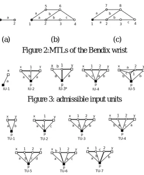
Chang and Tsai [3] pointed out that each column in the structure matrix represents an MTL. An MTL describes a transmission path from the input to those joints which are driven by an input link. Note that the number of dof of an GRM with independent joint motion is equal to the number of MTLs associated with it. Figs. 2(a), (b) and (c) show the three MTLs of the Bendix wrist.
With the concept of decoupling an MTL into an input unit and several transmission units, Chen and Shiue [4] enumerate the atlas of admissible input and transmission units up to five links in graph represen-tation as shown in Figs. 3 and 4 respectively.
a 1 2 b a a b c 5 6 1 2 3 4 b a a b c 7 8 1 2 3 4 (a) (b) (c)
Figure 2:MTLs of the Bendix wrist
IU-1 a x IU-2 p a b x 1 a y IU-3* x a b p 1 a y IU-4 p b c x 1 a 2 y b IU-5 x b c y 1 a 2 p b
Figure 3: admissible input units
TU-1 p x y a b TU-2 p a b x 1 c y TU-3 p a b x 1 a 2 y b TU-4 p a c x 1 a 2 y b TU-5 p a b x 1 c 2 y d TU-6 p a b x 1 a 2 y c TU-7 1 b c p x b 2 y a
Figure 4: admissible transmission units The input and output links of a input unit are co-axial. For transmission units, the input and out links are in different axes.Both the input and transmission units contain a link which acts as the primary link on EOLC when different units are chained together.
Note that the admissible number of links for in-put units are not consecutive. Inin-put units with three links do not exist.
3. Constr uction of GRM
The construction of an GRM is shown in Fig. 5, in which a hierarchical model is used to demonstrate the relations between units, MTLs and the desired mechanism. For an GRM without redundant actuation, the number of MTLs is equal to the number of dof. Similarly, each MTL is formed with input and trans-mission units. The number of transtrans-mission units de-pends on how many joints are driven by the MTL while the number of input unit is always equal to one.
AGM MTL 1 (i joints) MTL 2(j joints) I. U T. U T. U I. U T. U T. U ... ... ... .... MTL n (k joints) ... T. U T. U I. U ... ... System Level Assembly Level Unit Level 1 i-1 1 j-1 1 k-1
Figure 5: Hierarchical model of GRM
4. Speed Ratio of Unit
Let i, j and k be three coaxial links, then the re-lative angular displacements among these three links can be related as:
k ,j j , i k , i q q q = + (4) where qi,j denotes the relative angular
displace-ments of link i with respect to link j.
Let links j and k be a gear pair and i be the car-rier. Then, links i, j and k form a fundamental circuit and a fundamental circuit equation can be written as:
i, k kj i, j q q q = (5)
For units having more than one gear pair, fun-damental circuit equation, such as eq. (5), can be set up according to the number of gear pairs in the unit. For example, the fundamental circuit equations of TU-7 in Fig. 4 can be written as
p , 1 x 1 p , x e q q = (6) 1 , 2 y , 2 1 , y y , 1 q e q q =− =− (7) p , 1 2 p 1 , p 2 p 1 , 2 e q e q q = =− (8)
Since links y, p and 1 are coaxial, from eq. (4), we have p , y y , 1 p , 1 q q q = + (9)
Substituting eq. (8) in eq.(7) yields p , 1 y 2 2 p y , 1 e e q q = (10)
Substituting eq. (10) in eq. (9), we have
p , y y 2 2 p p , 1 q ) e e 1 ( 1 q − = (11)
Let link x be the pre-connecting link and link y be the post-connecting link. By substituting eq. (11) in eq. (6), the angular displacement between the local input x and primary link p, qx,p, can be represented as a
function of the angular displacement between local output y and primary link p, qy,p, as
p , y f p , y y 2 2 p x 1 p , x q G q ) e e 1 ( e q = − = (12)
where Gf is called the forward gain associated with the TU-7 unit.
For the case link y is chosen as the local input and link x as local output, from eq. (12), angular dis-placement between qy,p and qx,p can be represented as
p , x b p , x x 1 y 2 2 p p , y q G q e ) e e 1 ( q = − = (13)
where Gb is called the backward gain associated with
the TU-7 unit.
Note that the number of fundamental circuit equations and coaxial equation(s) associated with the admissible geared units shown in Figs. 3and 4 is fairly limited. Hence, the angular displacement between the connecting links and the primary link of the admissi-ble geared units can be easily derived. Taadmissi-bles 1 and 2 respectively show the forward and backward gains associated with the admissible input and transmission units. Also note that for the two-link input unit, the forward and backward gains are equal to one.
Table 1 Gf Gb IU-1 1 1 IU-2 ey1e1x ex1e1y IU-3 y 1 p1e e -1 1 1y p1e e -1 IU-4 ey2e21e1x ex1e12e2y IU-5 y 2 12 1 pe e e 1 1 − 1-ep1e12e2y Table2 Gf Gb TU-1 eyx exy TU-2 ey1e1x ex1e1y TU-3 ey2e21e1x ex1e12e2y TU-4 ey2e21e1x ex1e12e2y TU-5 ey2e21e1x ex1e12e2y TU-6 12 1 p 2 y e e 1 e − (1-ep1e12)e2y TU-7 y 2 2 p x 1 e e 1 e − ex1(1-ep2e2y) ... Last TU TUs IU i i+1 j j+1 j+2 i+k-1 i+k-2 j+k-2 j+k-1 j+k i+k-3 Figure 6: an MTL 5. Pr opagation between Units
Fig. 6 shows a typical mechanical transmission line with length equal to k. The connecting links are numbered as j, j+1, . . . ,and j+k, and the primary links
are numbered as I, i+1, . . . ,and i+k-1 for the input unit
and transmission units, respectively. The rotation of connecting link j with respect to primary link i, qj,i, is
considered the input angular displacement. For the first unit, the angular displacement between qj,i and
qj+1, i, from eq. (12) and Table 1, can be written as
i, 1 j 1 ,j i, j G q q = + (14)
where Gj,i denotes the forward or backward gain of the
i-th unit of mechanical transmission line with con-necting link j as input link.
For the second unit of the mechanical transmis-sion line (i.e., the first transmistransmis-sion unit), we have
1 i, 2 j 2 ,j 1 i, 1 j G q q+ + = + + (15)
The coaxial condition between the first two units, can be written as
1 i 1 i, 1 j i, 1 i 1 i, 1 j i, 1 j q q q è q+ = + + + + = + + + + (16)
By substituting eq. (15) into (16), the angular dis-placement of the post-connecting link of the first unit, link j+1, with respect to its associated primary link, link i, can be written as
1 i, 2 j 2 ,j 1 i i, 1 j è G q q+ = + + + + (17)
Similarly, the angular displacement of the post-connecting link of the (k-2)-th unit, link j+k-2, with respect to its associated primary link, link i+k-3, can be written as 2 k i, 1 k j 1 k ,j 2 k i 3 k i, 2 k j è G q q+− + − = + − + − + − + − (18) And the angular displacement of the post-connecting link of the (k-1)-th unit, link j+k-1, with respect to its associated primary link, link i+k-2, can be written as
1 k i, k j k ,j 1 k i 2 k i, 1 k j è G q q+− +− = + − + + + − (19)
Note that the post-connecting link j+k of the k-th transmission unit will be assigned as primary link i+k to form the last joint influenced by the mechanical transmission line. Hence,
k i 1 k i, k i 1 k i, k j+ + − =q+ + − =è+ q (20)
Substituting eq. (20) into eq. (19) yields k i k ,j 1 k i 2 k i, 1 k j è G è q+− +− = + −
+
+ (21)By substituting eq. (21) into eq. (18), we have ] è G è [ G è qj+k−2i,+k−3= i+k−2+ ,jk−1 i+k−1+ ,jk i+k ] è ) G ( [ è i k 1 k i m i m 1 k n ,jn m 2 k i + ∑ ∏ = + − + = − − = − + (22)
From eq. (22), it can be shown that angular displace-ment of the post connecting link of the g-th unit, link z, with respect to its primary link, link p, of a MTL with length equal to k, can be written as
] m è ) G ( [ è q p(k g) 1 2 p m ) 1 g p ( m 1 g n ,jn 1 p p , z = + ∑ ∏ + − + + = + − − + = + (23)
From eq. (23), eq. (17) can be rewritten as
] è ) G ( [ 1 i è q i k 2 i m i m 2 n j,n m ,i 1 j = + + ∑ ∏ + + = − = + (24)
By substituting eq. (24) into eq. (14), the input angular displacement, qj,i, of a k-length mechanical
transmis-sion line can be written as function of joint angles:
] è ) G ( [ q i k 1 i m i m 1 n j,n m j,i = ∑ ∏ + + = − = (25)
For the mechanical transmission line corre-sponding to Fig. 2(b), IU-1 is used as input unit and TU-1 is used as the first and the last transmission units. From Tables 1 and 2, we have G5,1 = Gf)IU-1 =1, G5,2 =
Gf)TU-1 = e65 and G5,3 = Gf)TU-1 = e46. Thus, eq. (24) can
be rewritten for the input angular displacement, q5,1, 3 46 65 2 65 1 3 1 m m 1 n 5,n m 1 , 5 [( G )è ] è e è e e è q = ∑ ∏ = + + = = (26) For the mechanical transmission line corresponding to Fig. 2(c), from Tables 1 and 2, we have G7,1 = Gf)IU-1 =
1, G7,2 = Gf)TU-1 = e87 and G7,3 = Gf)TU-1 = e48. Thus, the
input angular displacement, q7,1, from eq. (24), can be
written as 3 48 87 2 87 1 3 1 m m 1 n 7,n m 1 , 7 [( G )è ] e e e q = ∑ ∏ =θ + θ + θ = = (27) For the direct drive mechanical transmission line cor-responding to Fig. 2(a), we have G2,1 = Gf)IU-1 = 1 and
1 è 1 è 1 , 2 G 0 , 1 = = q (28) Let Φ = [q2,1, q5,1, q7,1] T be the displacement
vector associated with the actuator-space and Θ = [θ1, θ2, θ3]
T be the displacement vector associated with the
joint-space. According to eq. (1), we can derive an structural matrix from eqs. (26-28) which is identical with that in eq. (3).
It can be observed that the forward and back-ward gains of the input unit and transmission units provide a better insight of the effects on the torque transmission of each mechanical transmission line. 6. Decomposition of Desir ed Mechanism
In the following, a design methodology for GRM is presented. With the determined number of links assigned to the units, suitable units from Figs 3 and 4 can be selected for further synthesis.
6.1 Decomposition constraints
The following equation must be satisfied by an n-dof, m-link GRM (Chen and Shiue, 1996):
m n mi ni i n = + + − + =
∑
( 1) [ ( 1)] 1 (29) where mi is the number of links of the i-th MTL.In eq.(29), the summation of mi represents the num-ber of links for distribution at the assembly level which can be denoted as Nm. Using the definition of
Nm, eq. (29) can be rearranged as:
Nm m n ni i n = − − + + =
∑
( 1) ( 1) 1 (30) For an l-link k-joint MTL, the following equa-tion must be satisfied (Chen and Shiue, 1996):l liu ltu j k j k = + − − = −
∑
) ( ) 1 1 1 (31)where liu is the number of links of the input unit and
ltu)j is the number of links of the j-th transmission unit.
In eq.(31), the first two terms on the right hand side represents the number of links for distribution at the unit level, Nu. Eq (6) can be rearranged as:
Nu = + −l k 1 (32)
6.2 Composition Polynomial
After deriving the number of links for distribu-tion, the following work is to distribute it into subsys-tems in the succeeding level.A lexicographic method is used by applying the Hindenburg algorithm (An-drew, 1976). The composition polynomial, Cp, is de-rived to show all possible link distributions of the
desired mechanism under the link number specifica-tion.
The composition polynomial is constructed ac-cording to the model in Fig. 5. Acac-cording to Chen and Shiue [4], three kinds of MTL configurations exist for 2-dof GRMs, and ten kinds of MTL configurations exist for 3-dof GRMs. Cp for 3-dof GRMs at the
sys-tem level can be written as:
C a T a T T a T T a T T a T T T a T T a T a T T a T T a T p= + + + + +1 1 + + + + 3 2 1 2 2 1 3 1 2 3 1 4 1 1 2 2 5 1 1 2 1 3 1 6 11 32 7 23 8 22 31 9 21 32 10 33 (35) where Tn denotes an MTL which drives n joints and the superscripts of T represent the number of MTLs which influencing the same number of joints. The coefficient ap represents the total number of
admissi-ble link distributions and it is determined until the unit level is reached.
At the assembly level, the given number of links is to be distributed into each MTL. Applying the same approach to each term in eq.(35), the assembly-level Cp for eight-link GRMs can be derived as:
C a t t t t t t a t t t t t t a t t t t t t a t t t t t t t t t a t t t t t t p= + + + + + + + + + + + 1 121216 121414 2 121524 121425 3 121238 121436 4 122426 122525 142424 5 122437 122536 ( ) ( ) ( ) ( ) ( ) a t t t a t t t a t t t 6 1 2 3 6 3 6 7 242425 8 242436 ( ) ( ) ( ) + + (36)
In the equation above, a9 and a10 terms are
eliminated since the number of links for distribution is not enough for the two kind of MTL configurations.
In turn, the number of links of each MTL is to be distributed into input unit and transmission units. Eq.(36) can be expand to the unit-level Cp as:
C a I I I a I I I S I I I S a I I I S S I S S I S S I S S I I I S S a I I S I S I S I I S p= + + + + + + + + + + 1 2 4 4 2 2 5 2 3 2 4 2 4 3 2 2 2 3 5 2 5 3 2 4 4 4 3 3 2 4 2 3 3 4 2 2 3 2 5 4 3 2 2 4 {[( )( )( )]} {[( )( )( )] [( )( )( )]} {[( )( )( )] [( )( )( )]} {[( )( )( )] [( )( )(I S I I S I S a I I S I S S I S S I I S I S S a I I S S I S S a I S I S I S a I S I S I S S 2 4 4 2 3 2 3 5 2 2 3 2 3 4 2 4 3 2 2 4 2 3 3 6 2 2 3 3 2 3 3 7 2 3 2 3 2 4 8 2 3 2 3 2 3 3 )] [( )( )( )]} {[( )( )( )] [( )( )( )]} {[( )( )( )]} {[( )( )( )]} {[( )( )( )]} + + + + + + + (37)
Eq.(37) reveals all possible units selections to construct the desired mechanism. After replacing Im
and Sn with the corresponding numbers of admissible
units in Figs 3 and 4, the coefficients of Cp for 3-dof,
8-link GRMs are determined as:
a1=9, a2=6, a3=23, a4=15, a5=3, a6=1, a7=3, a8=1.
From the derived Cp, the starting point of the
design is extended from only the link number specifi-cation to the complete unit combinations under the design constraint. These unit combinations show ad-missible mechanisms in symbolic form.
7. Synthesis of the Desir ed Mechanism 7.1 Utilization of Cp
The coefficients of Cp reveals how many
admis-sible mechanisms exist corresponding to each MTL configuration. From the system-level Cp, the designer
can choose what kinds of MTL configurations are to
be used. Note that, an MTL configuration may corre-spond to different structure matrices. However, differ-ent structure matrices which have the same MTL con-figuration will have the same number of correspond-ing admissible mechanisms. With the specification in MTL configuration, the corresponding terms in the unit-level Cpindicate the proper selection of units.
7.2 Enumeration of MTLs
From these given information in the unit-level Cp, the corresponding MTL can be enumerated
ac-cording to the following steps [4]:
Step 1 : Connect the units according to the specified sequence and construct the joints by rearranging the coaxial links.
Step 2 : Assign the last primary link
Fig. 6(a) shows the enumerating process for the MTL in fig. 2(b).
7.3 Enumeration of GRMs
After the MTLs for desired GRMs are gener-ated according to the approach in the previous section, the admissible mechanisms can be constructed ac-cording to the following steps:
Step 1 : Choose the form of structure matrix
The form of structure matrix must be determined first since an MTL configuration may have different types of structure matrices.
Step 2 : Combine MTLs according to the selected structure matrix
Fig. 6(b) shows the combination of MTLs for Ben-dix wrist. a 5 1 b 5 6 2 a b c 6 4 3 a 5 1 b 6 2 a b c 4 3 4
(a) Units combination for an MTL
b a a b c 5 6 4 b a a b c 7 8 1 2 3 4 3 1 1 2 2 b 1 a 2 3 a 4 b c a b 5 6 7 8 (b) MTL assembly for an GRM Figure 7: Synthesis process of GRM 8. Conclusion
1. Efficient Methodology for Kinematic Analysis A systematic methodology for the derivation of kinematic analysis for a general class of geared robot manipulators has been developed. The approach is based on the concept that a geared robot manipulator can be viewed as the integration of an equivalent open-loop chain and several mechanical transmission lines and each mechanical transmission line as an
input unit and several transmission units connected in series. It is shown that forward gains and/or backward gains of admissible input and transmission units can be systematically derived. It is also shown that the angular displacement of the connecting links with respect to its associated primary links can be sys-tematically represented as a function of joint angular displacements and forward and/or backward gains by a unit-by-unit evaluation procedure. This method leads to an automated derivation of the kinematic relations between the actuator-space and joint-space without the need of solving a set of linear equations simultaneously. This unit-by-unit evaluation proce-dure provides a better insight of the effects of the input and transmission units on the torque transmis-sion of each mechanical transmistransmis-sion line.
2. Design Methodology for GRMs
An efficient design methodology for GRMs have been developed. It is shown that the searching for admissible mechanisms can be carried out in sym-bolic form by deriving the composition polynomial. A GRM can be decomposed into the system level, as-sembly level and unit level as a hierarchical model. According to the model, the given link numbers of the desired mechanism are distributed into MTLs in the assembly level and then into units in the unit level. These distributions are recorded in the composition polynomial and thus the configurations of admissible mechanisms are shown. This is much more efficient than enumerating graphs for admissible mechanisms directly. It is also shown that by selecting units from the composition polynomial, the graph enumeration can start exactly for the desired mechanisms.
Refer ence
1. Andrew, George. E., The Theory of Partitions, Addison-Wesley Pub. Co., Reading, Mass., pp. 230-237 (1976).
2. Belfoire, N. P., and Tsai, L. W.,Second National Conference on Applied Mechanisms and Robotics, Paper No. VIB.5,( No. 1) (1991).
3. Chang S. L., and Tsai, L. W., IEEE Trans. On Robotics and Automation, 6, , 97 (1990).
4. Chen, D. Z., and Shiue, S. C.,Proceedings of The 1996 ASME Design Engineering Technical Con-ferences and Computers in Engineering Confer-ence, Paper No. 96-DETE/MECH-1024 (1996). 5. Freudenstein, F., Longman, R. W., and Chen, C.
K., ASME Transaction, Journal of Mechanisms, Transmissions, and Automation in Design, 106, 371 (1984).
6. Freudenstein, F., ASME Journal of Engineering for Industry, 93, Series B, 176 (1971).
7. Lin, C. C., and Tsai, L. W., Proceeding of the First National Conference on Applied Mecha-nisms and Robotics, Paper No. 89-AMR-2A-3(1989).
8. Litvin, F. L. and Yi, Z., The international Journal of Robotics Research, 5, 75 (1986).
9. Ma, R., and Gupta, K. C., Journal of Robotic Systems, 6, 509 (1989).
10. Ma, R., and Gupta, K. C., ASME Journal of Mechanical Design, 116, 326 (1994).
11. Tsai, L. W., IEEE J. of Robotics and Automation, 4, 150 (1988).