國
立
交
通
大
學
資訊科學與工程研究所
碩
士
論
文
應用於 VANET 環境下
以車輛密度為基礎之緊急訊息廣播
A Vehicle-density-based Forwarding Scheme for Emergency
Message Broadcast in VANETs
研 究 生:曾宇田
指導教授:簡榮宏 教授
中 華 民 國 九 十 九 年 三 月
ii
應用於 VANET 環境下以車輛密度為基礎之緊急訊息廣播
A Vehicle-density-based Forwarding Scheme
for Emergency Message Broadcast in VANETs
研 究 生:曾宇田 Student:Yu-Tian Tseng
指導教授:簡榮宏 Advisor:Rong-Hong Jan
國 立 交 通 大 學
資 訊 科 學 與 工 程 研 究 所
碩 士 論 文
A Thesis
Submitted to Institute of Computer Science and Engineering College of Computer Science
National Chiao Tung University in partial Fulfillment of the Requirements
for the Degree of Master
in
Computer Science
March 2010
Hsinchu, Taiwan, Republic of China
應用於 VANET 環境下以車輛密度為基礎之緊急訊息廣播
研究生:曾宇田 指導教授:簡榮宏 博士
國立交通大學資訊科學與工程研究所
摘
要
車載隨意網路(Vehicular Ad Hoc NETwork, VANET)主要提供車輛意外緊急 警告服務與一般性的資料傳送。為了讓駕駛者免於遭受緊急事故的波及,快速的 緊急訊息傳遞為目前車載隨意網路上炙手可熱的研究議題。在緊急訊息多站廣播 (Multi-hop broadcast)的方法中,下一轉送站點(Next hop forwarder)的選擇模 式主要分為兩種:(1)傳送者導向轉送法藉由獲得鄰居資訊由傳送者選擇最佳的 下一轉送站點;(2)接收者導向轉送法採用分散式的方法,由各轉送者自行決定 何時將訊息送出,讓最早轉送出訊息者成為下一轉送站點。本論文提出一個植基 於車輛密度的緊急訊息廣播法(Vehicle-Density-based Emergency Broadcast,簡稱 VDEB)來解決傳輸者導向方法中的高額外負載(Overhead)問題,以及接收者 導向方法中可能發生長延遲時間問題。實驗結果顯示,我們提出的 VDEB 只需 非常低的額外負載便可達成相當不錯的延遲時間狀況。
ii
A Vehicle-density-based Forwarding
Scheme for Emergency Message
Broadcast in VANETs
Student:Yu-Tian Tseng Advisor:Dr. Rong-Hong Jan
I
NSTITUTE OF
C
OMPUTER
S
CIENCE AND
E
NGINEERING
N
ATIONAL
C
HIAO
T
UNG
U
NIVERSITY
Abstract
The extension of wireless technology, vehicular ad hoc network (VANET), provides emergency warning services and general data transmission services. To rescue more drivers from being involved in an emergency event on the road, fast emergency message propagation is an important issue in VANET studies. There are two types of multi-hop broadcasting forwarder selection scheme for emergency broadcasting, known as sender-oriented schemes and receiver-oriented schemes. The sender-oriented schemes maintain the neighbor information to choose the best forwarder before broadcasting the message while the receiver-oriented schemes distributedly elect the forwarders. In this thesis, we proposed a vehicle-density-based emergency broadcast (VDEB) scheme to solve the problem of high overhead in sender-oriented schemes and long delay in receiver-oriented schemes. The simulation results show that our VDEB scheme can achieve a better performance with low delay and little overhead.
致謝
在此,我要感謝這兩年裡,指導我進行研究的簡榮宏老師,感謝老師不厭其 煩的教導我學術研究的進行方式與研究方法的探討。藉由不斷研究方向分析與方 法改進,終於能夠提出此一完整的方法。 除了指導教授之外,實驗室的夥伴也是我研究生活重要的推手。感謝實驗室 學長姐(世昌、安凱、嘉泰、蕙如、文彬、家瑋、鈺翔、奇育、宇翔、允琳、俊 傑、佑笙、敬之、子興、志賢、淑盈)、同學(嘉瑋)以及學弟妹(欣雅、良叡、冠 傑)的共同努力,以及生活上的協助與陪伴。學業上的共同作業以及許多的情感 交流讓我研究生涯留下許多深刻的印象。 最後我要感謝家人以及眾多支持我走過研究生活的朋友們,感謝你們一路上 的鼓勵與支持,讓我能夠堅持到最後,完成人生重要的里程碑。在此,本文獻要 獻給關懷勉勵我的家人與友人們。iv
Contents
Chapter 1 Introduction ···1
1.1 Standards for VANET and the ITS ···1
1.2 Multi-hop broadcast and its challenges ···3
Chapter 2 Related Works ···7
2.1 Sender-oriented relay selection ··· 12
2.2 Receiver-oriented relay selection ··· 14
Chapter 3 Vehicle-Density-based Emergency Broadcast ……….17
3.1 System Model and Assumptions ··· 17
3.2 Neighbor Table and Hello Message ··· 18
3.3 Emergency Message Format ··· 20
3.4 Vehicle-Density-based Emergency Broadcast ··· 21
3.4.1 DBS scheme··· 21
3.4.2 VDEB scheme ··· 22
3.4.2.1 Vehicle-density measurement ··· 23
3.4.2.2 Emergency message broadcast ··· 24
3.4.2.3 Receiver-waiting process ··· 27
Chapter 4 Simulation Results and Analysis………..28
4.2 Results Analysis··· 29 Chapter 5 Conclusion ··· 38 References ··· 39
vi
List of Figures
Figure 1. The transmission range of the sender (the red car) with the risk zone ···2
Figure 2. Vehicle distribution in a dense network ···5
Figure 3. Vehicle distribution in a sparse network ···5
Figure 4. State machine of EEBL message forwarders ···9
Figure 5. Emergency packets and their accompanying priopulses ··· 10
Figure 6. The LRBT protocol ··· 11
Figure 7. Backbone and the relative factors··· 13
Figure 8. The distance between the sender, the receiver, and the common neighbors15 Figure 9. Hello message format ··· 18
Figure 10. Emergency message format ··· 21
Figure 11. Sender’s transmission range is partitioned into multiple rings ··· 23
Figure 12. Vehicle density measurement procedure ··· 24
Figure 13. Emergency message broadcast procedure ··· 25
Figure 14. The case of maximum ring width ··· 26
Figure 15. The case of minimum ring width ··· 26
Figure 16. Average delay of MCDS··· 30
Figure 17. Farthest end-to-end delay of MCDS ··· 30
Figure 18. Average delay of VDEB ··· 31
Figure 20. Average delay comparison ··· 33
Figure 21. Average farthest end-to-end delay comparison ··· 33
Figure 22. Average Retransmissions comparison ··· 35
Figure 23. Delay percentiles comparison··· 36
viii
List of Tables
Table 1. Neighbor table of vehicle 17 when the time is 200 ··· 19
Table 2. Simulation parameters ··· 29
Table 3. Average retransmissions of VDEB··· 32
Chapter 1
Introduction
As the growing up of wireless technology, the application of wireless technology, such as the IEEE 802.11 families, has been extended to the road network providing various useful services for drivers. The wireless technology used in the road situation, called vehicular ad hoc networks (VANET), is an extension of mobile ad hoc networks (MANET) based on the IEEE 802.11. The differences between VANET and MANET are that the moving speed of mobile nodes in VANET is higher than those in MANET and the moving trajectory of mobile nodes in VANET is limited on the road not random as in MANET. The former causes high dynamic topology changes in VANET and the latter makes the mobility of mobile nodes predictable.
1.1 Standards for VANET and the ITS
The IEEE 802.11p is a draft amendment to the standard IEEE 802.11 to add the wireless access in vehicular environments (WAVE). The IEEE 802.11p defines enhancement to 802.11 providing intelligent transportation systems (ITS) applications. The IEEE 802.11p will be used as the groundwork for Dedicated Short Range Communications (DSRC) [1] to provide data exchange between high-speed vehicles (called inter-vehicle communications, IVC) and between the vehicle and the roadside infrastructures (called roadside-to-vehicle communications, RVC).
2
The applications of VANET can be classified into two main categories: the safety applications and the general data routing services. The safety applications provide one-to-all emergency message broadcasting for receivers in a predefined region, such as electronic break light, lane changing assist, and road condition reports. These applications are usually life critical. Therefore, the data should not only be successfully received by the receivers but be received in a very short time to provide the driver more reaction time. The general data routing provides one-to-one data routing or one-to-all data broadcasting for services, such as entertainments, route planning, and communications. The data transmission requirement of this type of services is reliability, namely the packets should be successfully received by the receivers.
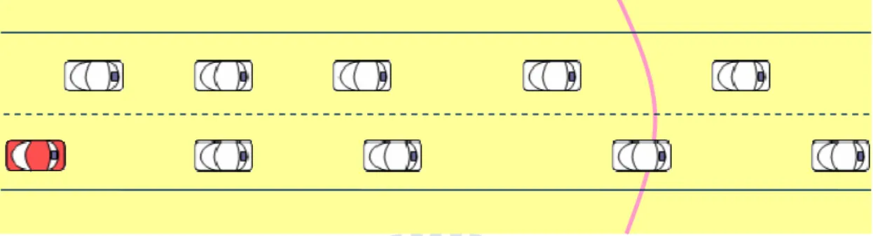
In this thesis, we focus on broadcast of emergency message. When an emergency event occurs, an emergency message (may be multiple) will be generated by an observer vehicle and be broadcasted. The emergency message is broadcasted in a risk zone (usually several kilometers). Generally the one-hop broadcast range is just several hundred of meters and can not cover the entire risk zone, as showed in Figure 1. Therefore, multi-hop broadcast is required to broadcast the message to all the vehicles in the whole risk zone. In fact, the IEEE 802.11 does not support multi-hop broadcast. Hence many schemes for multi-hop broadcast are proposed to disseminate the emergency message an efficiently and reliably.
Figure 1. The transmission range of the sender (the red car) with the risk zone One-hop broadcast range
R
For the most emergent situation, e.g. vehicle collisions, the limit of propagation time of emergency message is extremely low. Some researches focus on Cooperative Collision Avoidance (CCA) [2, 3] to broadcast collision avoidance message in a very short latency in order to save as many as victim vehicles if possible. In order to ensure all the victim vehicles in the risk zone can receive the emergency message in time, we consider two important means to reduce the message propagation latency. The key point is to reduce the hop counts needed to propagate the message to the entire risk zone. This can be done by choosing the forwarders such that the hop distance is maximized. Moreover, the additional waiting time before rebroadcasting the message should be as small as possible to ensure the low latency.
1.2 Multi-hop broadcast and its challenges
The main challenge of multi-hop broadcast is the broadcast storm problem. Without appropriate relay node selection, there will be many nodes rebroadcasting the message. Broadcasting in IEEE 802.11 is unreliable due to no handshaking process before transmission. Large amount of receiving nodes broadcasting the same message will make the problems of contention for channel and serious packet collisions. Rebroadcasting due to transmission fail makes the problem worse further.
To reduce the transmission overhead and meet the requirement of emergency broadcast, there are two categories of relay node selection methods: sender-oriented relay selection and receiver-oriented relay selection. Sender-oriented methods [4-12] use accurate neighbor positions to select the best relay node (usually the farthest node from the sender) claiming the minimum hop count and no additional waiting time. High frequency beacon messages are used to construct virtual structures to achieve such task. Receiver-oriented methods [13-16] use contention to automatically elect the forwarder(s). All the one hop receivers concerning about the emergency event enter
4
the contention phase after receiving the message. They calculate a backoff time and back off this time before rebroadcasting the message. The node with shortest backoff time will rebroadcast the message first. All the other nodes overhearing this broadcast will cancel their broadcasting process due to the election of the forwarder. The parameters for backoff time calculation can be the distance, vehicle velocity, vehicle’s moving direction, number of nodes, and so on. The forwarders of receiver-oriented methods could be multiple when there are multiple vehicles having similar backoff time.
Both of the existing schemes of these two types of relay node selection methods have their drawbacks. In a dense network, for a given region, there will be more vehicles than in a sparse network. Sender-oriented schemes mainly rely on the accurate position data (or something else) to select the relay node. To maintain the accurate data, the broadcasting period of beacon messages should be very short. The inaccurate data may cause the sender to select a relay node outside the transmission range and thus the forwarding process will fail. Restarting the broadcast process after the failed forwarding will cost additional time, and the failure of forwarding process downs the performance of sender-oriented schemes.
On the other hand, the latency of the receiver-oriented schemes usually gets much longer than in a sparse network. The backoff time is usually reversely proportional to the distance between the sender and the receiver. The forwarders in a sparse network have higher chance to be far from the border of sender’s transmission range because the inter-vehicle spaces between vehicles are larger than in a dense network. Also the receivers do not know each other in receiver-oriented schemes. Hence the forwarders in a sparse network sometimes have to wait for a long time before rebroadcasting. In Figure 2, the farthest vehicle within the red vehicle’s transmission range is almost at the transmission border, and it has a minimum backoff time. However, in Figure 3, the
position of the farthest vehicle in the red vehicle’s transmission range is just half of the maximum transmission range, it will backoff a long period of time before forwarding the message. The number of vehicles which have similar backoff time grows up as the density of vehicles gets higher. This makes the contention and collision problem more serious in a dense network.
Figure 2. Vehicle distribution in a dense network
Figure 3. Vehicle distribution in a sparse network
To solve the problem of receiver-oriented schemes, this thesis proposes a vehicle-density-based emergency broadcast (VDEB) protocol for broadcasting emergency messages in VANET. We calculate the backoff time of receiving vehicles based on the estimated vehicle density. To reduce the overhead, the beacon messages are broadcasted with long broadcasting period to construct the neighbor table. This is a novel receiver-oriented scheme with slight overhead. Simulation results show that the broadcasting latency and the number of rebroadcasts for each emergency message are improved. Especially, the VDEB can achieve a very low latency close to the sender-oriented schemes without exhausting the network.
6
The rest of this thesis is organized as follows. In chapter 2, we review the related works about multi-hop broadcast. Then, our VDEB protocol will be introduced in chapter 3. Chapter 4 shows our simulation results and analysis. Finally, this thesis is concluded in chapter 5.
Chapter 2
Related Works
Broadcast storm problem is the first problem that we have to solve for designing a multi-hop broadcast protocol. Without any mechanism to control the traffic caused by the multi-hop broadcasting, simple flooding [17] just lets all the receivers in the message propagation direction rebroadcast the emergency message once till whole nodes are noticed. It is easy to be implemented in VANETs but the high packet redundancy causes serious packet loss rate and wastes bandwidth. Not only safety services are influenced but general services.
Some studies have been proposed to reduce redundant transmissions to suppress the broadcast storm problem of simple flooding.
(1) Counter-based: In counter-based schemes [17], the nodes wait a period of time before rebroadcasting the message. During this time period, the waiting node continuously overhears the channel for other nodes’ forwarding of the same message waiting in its waiting process. If the number of forwarding nodes which rebroadcast the same message reaches a predefined threshold when the timer of waiting node expires, the waiting node will cancel its rebroadcast process. This mechanism can control the traffic caused by the emergency message but the latency requirement is not fulfilled.
8
scheme with probability forwarding mechanism. Every node has a probability to rebroadcast the message. The probability is usually a preconfigured value. The performance cannot be guaranteed in any vehicle density situation. In addition, like counter-based schemes, the latency is usually not considered as well.
(3) Location-based: Location-based schemes [13-16] make rebroadcast decisions based on the position of the mobile node. The farther node within the transmission range is distributedly chosen as the forwarder by using the positioning data of the previous-hop node and the receiving node its own. This type of schemes generally does not know other receivers’ states, the forwarder has to defer to forward the message. This increases the broadcasting delay. (4) Neighbor knowledge-based: Different from the three types of methods
mentioned above, neighbor knowledge-based schemes [4-9] collect neighbor knowledge frequently to maintain accurate neighbor information. With the accurate neighbor information, usually positioning information, the farthest relay node can be chosen by the sender before broadcasting the emergency message. Although the best relay can be quickly chosen while no additional time should be taken, the overhead to disseminate node information is frequently awful.
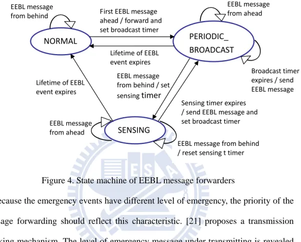
Beside the broadcast storm problem, reliability and priority are also the concerned issues. Broadcasting region or abiding geocast are introduced in some papers [18-20]. Continuously broadcasting emergency messages in a predefined region will encounter the problem of redundant transmission. [18] and [19] adopt the state machine, as shown in Figure 4, to mark each of the vehicles in the broadcast region a state. Whether to rebroadcast the message or not is according to the role of the vehicle. Thus, the number of broadcasting vehicles can be minimized by benefiting from state
Broadcast timer expires / send EEBL message
machine. In [20], the concept of safety line is described. The message should be delivered to the vehicles in time before they pass the safety line. There are at most two broadcasting vehicles in the broadcast zone, one for each direction.
Figure 4. State machine of EEBL message forwarders
Because the emergency events have different level of emergency, the priority of the message forwarding should reflect this characteristic. [21] proposes a transmission blocking mechanism. The level of emergency message under transmitting is revealed by a pulse transmitted in the control channel (the emergency message is transmitted in the data channel). Figure 5 shows emergency packets and their accompanying priopulses. The higher level emergency messages have longer active part of the pulse. The random pause part of the pause provides the chance for higher level emergency messages to block the under transmitting lower level message.
Sensing timer expires / send EEBL message and set broadcast timer EEBL message from behind / set sensing timer First EEBL message ahead / forward and set broadcast timer Lifetime of EEBL event expires Lifetime of EEBL event expires EEBL message from behind / reset sensing t timer EEBL message from ahead EEBL message from ahead EEBL message from behind NORMAL SENSING PERIODIC_ BROADCAST
10
Figure 5. Emergency packets and their accompanying priopulses. A is the message source, B is one of A’s neighbors, and C is a hidden terminal to A [21].
The higher level messages have smaller contention window for transmitting active part of the pulse. The message with smallest contention window has higher chance to snatch the power to use the data channel. If the transmitting node senses an active pulse in its random pause part of pulse, it will stop transmitting its emergency message. In [22], message piggybacking is used to bundle multiple emergency messages into a single packet. The message selection problem is encounter due to the limit message number of one single packet, which has the purpose to limit the packet size. Large packet size will consume more channel capacity. To select the piggybacked messages, two principles are considered: deadline and distance. The former usually has relevance with the emergency level of the emergency message.
EMDOR [23] has the goal to ensure all of the victims receiving the emergency message. The acknowledgement message is not only received by the sender, but also received by the potential receivers who overhear this message. Then the potential receivers check whether the acknowledged emergency message has received before. If the acknowledged emergency message has not been received, it can send a request to the designated relay node for retransmitting the message once.
Because the broadcast scheme of 802.11 is not reliable owing to no handshaking process is done before broadcasting the data packet, the hidden terminal problem
A
B
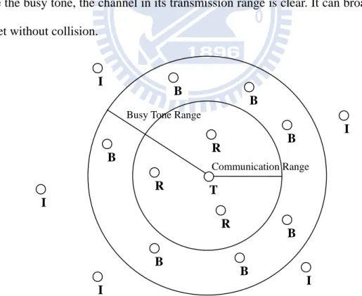
arises and has big impact in dense network. This problem causes packet collisions and retransmission makes the delay longer. This has the influence on the requirement of latency of emergency messages. A two-channel scheme is proposed in [21]. The emergency messages are transmitted in the data channel. Meanwhile, a pulse is transmitted in the control channel to block other node from transmitting. No mobile node is allowed to transmit a packet whenever it senses the active pulse in the control channel. The pulse also provides the function of priority as mentioned before. Busy tone [24] is used to inform other vehicles that “a node is broadcasting a message”. The tone is a signal which is not interfered with data packets. In addition, to let other vehicles “sense” the transmission of such a signal, the transmission range can be large than the one for transmitting data packets, as shown in Figure 6. Whenever a node wants to broadcast a packet, it first checks the existence of busy tone. If it does not sense the busy tone, the channel in its transmission range is clear. It can broadcast the packet without collision.
Figure 6. The LRBT protocol. T, R, B, and I refer to nodes in the transmitting, receiving, blocked and idle states, respectively
However, the most important issue of sending emergency message is how to
T
Communication Range Busy Tone Range
I R R R B B B B B B B I I I I
12
broadcast the message with a shortest delay, and how to avoid the broadcast storm problem while reducing the delay. Studies about these issues mainly focus on how to select the relay nodes on each hop. Schemes of relay node selection can be categorized based on who makes the decision. In sender-oriented schemes, the sender selects the next hop relay node before rebroadcasting the message; in receiver-oriented schemes, the relay node is elected by receivers distributedly after the message is received by the one hop receivers.
2.1 Sender-oriented relay selection
Sender-oriented schemes use high frequently transmitted beacon messages or handshaking mechanisms to choose a single node as the relay node.
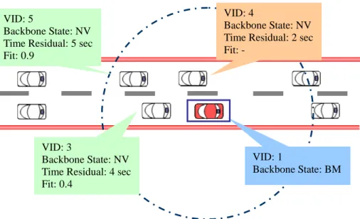
[4-6] are cluster-based schemes. [4] creates cells (or clusters) according to the first node in the network. The position of “the first node” is exchanged by periodic hello messages sent by all the vehicles. All the vehicles can calculate their cell number according to its position and the position of the first node. Each cell distributed elects a cell reflector to forward the packets. [5] creates and maintains clusters (or virtual backbones) considering the current distance between candidate backbone vehicles and the estimated lifetime of the wireless connection among neighbor backbone members. Figure 7 shows a part of the backbone structure. The purpose of this thesis is to maintain a stable backbone and reduce the overhead of backbone structure maintenance. [6] clusters the vehicles which are not keep safety distances with its neighbor vehicles. Vehicles in this system are required to equip with a device to measure the distance with the front and back vehicles. Emergency messages are rebroadcasted by the farthest vehicle of each sub-cluster head. [4] and [5] have bad channel utilization while the vehicle density gets larger. [6] requires the special device for inter-vehicle distance measurement and periodic beacon messages for maintaining
the structure. All of them are not realistic.
Figure 7. Backbone and the relative factors
[7-9] are MCDS-like (minimum connected dominating set like) schemes. [7] uses periodic beacon messages to acquire the vehicle ID of farthest vehicle in the transmission range of each vehicle. The failure of cluster mode is backed up by a receiver-oriented scheme. [8] not only assigns a relay node in the message but also assigns a secondary relay node to back up the failure of primary relay node. If the secondary relay node also fails, retransmission is triggered by the sender. [9] selects the relay node considering the prediction holding time (PHT) to prevent the inexistence of relay node when the message is broadcasted. This type of methods also encounters the problem of high overhead.
[10-12] try to select the farthest vehicle in the broadcast direction as relay node with at least 2-way handshakes every hop. Before the sender broadcasts the message, it sends a RTB (request to broadcast) message and waits for the CTB message. All the vehicles in the broadcast direction receiving the RTB message continuously send a jamming signal for a period of time. The length of the time period is proportional to the distance between the receiver and the sender of the RTB message. If the channel is
VID: 1
Backbone State: BM VID: 4
Backbone State: NV Time Residual: 2 sec Fit: -
VID: 3
Backbone State: NV Time Residual: 4 sec Fit: 0.4
VID: 5
Backbone State: NV Time Residual: 5 sec Fit: 0.9
14
over, it sends a CTB (clear to broadcast) message to the sender and suppresses other nodes’ transmission of the CTB message. Then the sender assigns the relay node according to the CTB message and broadcasts the message. Although the overhead of additional control packets is low, the additional time spent to select the relay node makes the delay longer. The CTB messages also have the problem of simultaneously transmission. This causes packet collision and the handshaking will restart again.
2.2 Receiver-oriented relay selection
Different from sender-oriented schemes, receiver-oriented schemes use contention to elect the relay node(s). The sender does not assign the relay node in the broadcasted message.
In [13], beacon messages are used to estimate the number of common neighbors in the transmission range with the sender. When a sender sends an emergency message, the neighbors list in the broadcast direction is attached in the message. Upon a receiver receives the message, it calculates the number of common neighbors between the nodes in the message and the nodes in the coming direction of the emergency message as showed in Figure 8. The node with the least number of common neighbors (it also means the farthest node) will have smallest differ time. If the farthest node has many common neighbors with the sender, the backoff time will be long. The overhead of beacon messages is the same as in the sender-oriented schemes.
Figure 8. The distance among the sender, the receiver, and the common neighbors In [14], the sender puts its position information acquired from the GPS device in the emergency message. Receivers adjust the contention window based on the distance between the receiver and the sender of the message. The farther the receiving node, the smaller the contention window. This gives the farther receiving node higher chance to forward the message. But, in a sparse network, the relay vehicle could be far from the border of the sender’s transmission range and has a large contention window. This will make the delay become higher than that in a dense network. [15] employs the opposite direction vehicles to relay the emergency messages. The backoff time is calculated based on the distance, the relative speed, and the direction. The higher relative speed vehicles have the chance to expand more coverage area than the lower ones. But the speed factor is almost negligible because the time during broadcasting is very short.
Vehicle density is employed in [16] to make the forwarding decision. Beacon messages are used to count the number of vehicles in one- or two-hop region. The number of vehicles is used to determine the rebroadcast probability, and the backoff time is calculated using the probability to differentiate the transmission. But how the
(a) Case 1: 1 common neighbor
(b) Case 2: 2 common neighbors
(c) Case 3: 4 common neighbors
A B
A
A
B
16
density information is used to calculate the backoff time is still an unresolved issue. The sender-oriented schemes are unrealistic because of its heavy overhead. Therefore, in this thesis, we proposed a vehicle-density-based protocol (VDEB) to solve the problem of long latency in receiver-oriented schemes. The performance is improved at the expense of little overhead.
Chapter 3
Vehicle-Density-based Emergency
Broadcast
In this chapter, we introduce our vehicle-density-based emergency broadcast (VDEB) scheme. In section 3.1, the system model of the simulation scenario and assumptions are described. Similar to the sender-oriented schemes, the beacon message is adopted by VDEB scheme. Section 3.2 will give the details of the beacon message format and its functions. The format of emergency message is described in section 3.3, and section 3.4 is the whole view of our VDEB scheme.
3.1 System Model and Assumptions
In the system model, we suppose the scenario of the road environment is a highway with 3-lanes considering single direction. Different from the urban situation, the speed limit in highway is higher, and there is no traffic light controlling the movement of vehicles. For simplicity, we only consider one single direction with 3-lanes, double direction, and the number of lanes can be easily extended according to the application requirement.
18
devices such as GPSs to acquire their own positions. In addition, to detect the emergency event, the vehicles should equip with several sensors for vehicle velocity or other else. For the transmission of packets, each vehicle is equipped with the WAVE DSRC device and the transmission range is set to 250 meters.
3.2 Neighbor Table and Hello Message
In sender-oriented schemes, beacon messages are periodically broadcasted to maintain the accurate position information of neighbor tables. In our system, the purpose of beacon messages is to inform other neighboring vehicles the presence of the beacon sender. In addition, the beacon messages provide some information for neighboring vehicles to roughly estimate the future positions of vehicles. Therefore, it can be used to count the number of neighboring vehicles around one vehicle (called vehicle density in this thesis). The beacon messages are called as hello messages in this thesis as their functionality.
The format of hello message is given in Figure 9. The first field of hello message denotes the vehicle’s identity. The second field is the position of vehicle when the message is generated. The third field is the vehicle’s velocity when the message is generated. The final field is the time stamp. With the position information, velocity, and the time stamp, the receivers can roughly estimated the current position of the hello sender by Velocity Timestamp e CurrentTim Position ition CurrentPos ( )* .
Vehicle ID Position Velocity Timestamp
Figure 9. Hello message format
The hello messages in sender-oriented schemes usually have position information and the timestamp but not velocity. In this type of schemes, vehicles only care about
the presence of neighbor vehicles. The accuracy of position information is reached by frequently transmitting the hello message. The validity of neighbor information is verified by checking the neighbor information in neighbor table to see if its lifetime expires or not. In other words, if the same vehicle information is received, the position information and the timestamp will be updated; otherwise the entry of this vehicle will just be removed.
Because the broadcast time of hello message of each vehicle is not synchronized, if we want to count the number of vehicles in transmission range, the broadcasting interval of hello messages needs to be small enough. Without the knowledge of velocity of other vehicles, one cannot know whether the vehicle is in its transmission range between two hello messages. This is why the broadcasting interval should be small to keep the position data fresh. By employing the velocity of neighboring vehicle to estimate its position after a period of time, every vehicle can roughly estimate the number of neighboring vehicles in its transmission range. If the current position of a vehicle is found not in its transmission range, the vehicle will not be a neighboring vehicle.
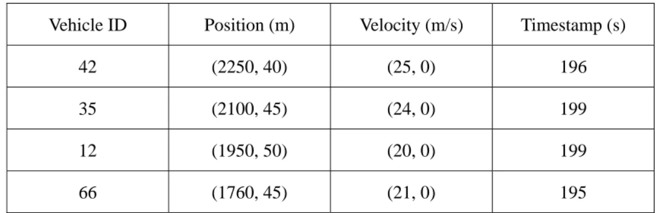
For example, suppose that the current time is 200. Assume no lane changing during the time period. The neighbor table of vehicle 17 is given in Table 1.
Table 1. Neighbor table of vehicle 17 when the time is 200
Vehicle ID Position (m) Velocity (m/s) Timestamp (s)
42 (2250, 40) (25, 0) 196
35 (2100, 45) (24, 0) 199
12 (1950, 50) (20, 0) 199
66 (1760, 45) (21, 0) 195
20
neighbors can be computed as follows.
CurrentPositionX(42) = 2250 + (200 – 196) * 25 = 2350 CurrentPositionX(35) = 2100 + (200 – 199) * 24 = 2124 CurrentPositionX(12) = 1950 + (200 – 199) * 20 = 1980 CurrentPositionX(66) = 1760 + (200 – 195) * 21 = 1865 255 ) 40 45 ( ) 2120 1865 ( ) 17 , 66 ( 4 . 140 ) 40 50 ( ) 2120 1980 ( ) 17 , 12 ( 4 . 6 ) 40 45 ( ) 2120 2124 ( ) 17 , 35 ( 230 ) 40 40 ( ) 2120 2350 ( ) 17 , 42 ( 2 2 2 2 2 2 2 2 Dist Dist Dist Dist
If the transmission range of vehicle 17 is 250 meters, the vehicle 66 is out of vehicle 17’s transmission range. That is, vehicle 66 is not a neighbor of vehicle 17.
Vehicle velocity and hello message broadcast interval influence the performance of our system. The impact of these factors will investigate in Chapter 4.
3.3 Emergency Message Format
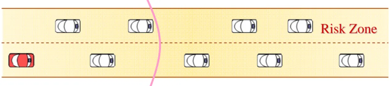
Generally, an emergency message has the information about the event, such as the position of the event, the event description, the event emergency level, the time period of event, the risk zone size of event, and the propagation direction of emergency message. In this thesis, we only consider the event position and the risk zone for simplicity. The propagation direction is a designated single direction according to our system model. The life time of emergency message is not presented as hop count or time period in our scheme. To reflect the characteristic of emergency event, we consider that the emergency message should be rebroadcasted until it reaches the end of the risk zone.
Beside the above information, we also add the ID of the source and the sender, the position of sender, and the ring width to the emergency message. We use ring-based method to divide the transmission range of the sender and the ring width is
determined by the relay node of message each hop. Therefore, the ring width is included in the message for receivers to calculate their backoff time. The position of relay node for receivers to determine which ring they are located at is included in the message. To differentiate the emergency event, the source ID of the emergency message is included and used with the event position to identify the event. Sender ID can be used for ACK-overhearing. ACK-overhearing is introduced in the next section. Figure 10 shows the emergency message format.
Source ID Event Position RZ Length Sender ID Sender Position Ring Width Figure 10. Emergency message format
3.4 Vehicle-Density-based Emergency Broadcast
In our system, vehicle-density-based emergency broadcast (VDEB), one-hop receivers of the emergency message distributedly elect the message forwarder(s). It is an evolution of distance based scheme (DBS) which will be compared with our scheme in Chapter 4.
Before introducing our VDEB scheme, we briefly describe the DBS scheme, and then explain why our VDEB scheme has better performance than DBS scheme.
3.4.1 DBS scheme
Whenever a vehicle wants to send or forward an emergency message, the position of sender or forwarder is included in the message for calculation of distance. Upon a vehicle receiving an emergency message, it computes the distance between itself and the message sender (or forwarder) according to the position information included in the message. Then the receivers will backoff a period of time before rebroadcasting the message. Any vehicle waiting in the backoff process overhearing the same message will cancel its own forwarding because the forwarder has been successfully elected. The backoff time is presented as contention window. The receiver adjusts its
22 contention window by min min max ) ( * ) , ( CW CW CW R s r dis R backoffCW , (1)
where R is the transmission range, dis(r,s) is the distance between the sender and the receiver, CWmax and CWmin are the maximum and minimum size of contention window,
respectively.
The function of contention window is to backoff the transmission a random period of time between 0 and CW (contention window size) SIFS (short interframe space, referred to the IEEE 802.11 standard) time. Hence the vehicle with larger contention window does not mean it will rebroadcast the message first. Statistically the farther node from the sender will have the higher chance to rebroadcast the emergency message first. But in a sparse network, the backoff time still has high chance to be long. Moreover, several vehicles may have similar contention window size. As the vehicle density grows up, the situation of multiple rebroadcast gets high. This might cause the network congestion and collisions.
3.4.2 VDEB scheme
To overcome the problem of long backoff time in a sparse network and many multiple retransmissions in a dense network in DBS scheme, we propose a backoff scheme not based on contention window adjustment. Messages will backoff a period of time then be sent to the MAC layer for contenting the wireless channel. The size of contention window is always the minimum size.
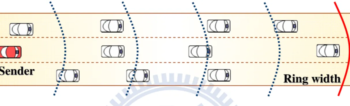
In the VDEB scheme, the transmission range of the message sender is partitioned into multiple of rings based on the ring width information provided by the sender. As shown in Figure 11, each ring is assigned a timeslot. The length of backoff time is increased in ring number. The vehicles in the most outer ring, says ring 0, have the shortest backoff time. If no successful transmissions are done by the vehicles in ring 0,
the vehicles in ring 1 will forward the message. If any vehicle successfully broadcasts the message, other vehicles will cancel their backoff process since the forwarding is done without collisions. Different from the DBS scheme, forwarders in VDEB are always the vehicles far from the sender. Usually, if there are vehicles in ring i, the vehicles in ring i+1 will not rebroadcast the message. In VDEB, the elected forwarders each hop is often less or equal to the number of lanes.
Figure 11. Sender’s transmission range is partitioned into multiple rings
In our VDEB scheme, the ring width is determined by the vehicle density and the neighbor information. And thus the backoff time can be adapted according to the traffic condition. Details of the VDEB scheme are given as follows:
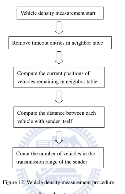
3.4.2.1 Vehicle-density-measurement
Each vehicle periodically broadcasts hello messages to inform others about its identity, position, and velocity. Whenever a vehicle wants to broadcast an emergency message, it has to calculate the ring width based on the vehicle density. The vehicle density measurement procedure is shown in Figure 12.
R
R
i
i
n
n
g
g
w
w
i
i
d
d
t
t
h
h
S
24
Figure 12. Vehicle density measurement procedure
3.4.2.2 Emergency message broadcast
Figure 13 is the flow chart of the emergency message broadcasting process. Before entering the broadcast-related part, if the vehicle is the message’s source, the event-related information is provided and attached to the message. After the relative information is ready, the vehicle density is measured for ring width calculation use.
Vehicle density measurement start
Remove timeout entries in neighbor table
Compute the current positions of vehicles remaining in neighbor table
Compute the distance between each vehicle with sender itself
Count the number of vehicles in the transmission range of the sender
Figure 13. Emergency message broadcast procedure
Basically, ring width in our scheme is the distance between the farthest vehicle and the border of transmission range. To avoid the estimated distance becoming unrealistic, we set the upper bound and lower bound for ring width. We assume that the vehicles have identical inter-vehicle distance with its immediate front and back
Emergency message broadcast
Is the vehicle the source of EM
Add event-related
information to the message
Vehicle density measurement
1. Compute the upper bound and lower bound of ring width. 2. Compute the rough ring width.
Yes
No
Compare ring width with ring_width_max and ring_width_min.
If ring_width > ring_width_max Then ring_width = ring_width_max If ring_width < ring_width_min Then ring_width = ring_width_min
Add ring_width to message then broadcast message
26
vehicles. Under this assumption, we determine the maximum ring width and minimum ring width as follows.
The needed maximum ring width appears in the case that all the vehicles drive side by side (see Figure 14). Hence the maximum ring width can be calculated by
N l R th
MaxRingWid *2* , (2) Where R is the transmission range radius, l is the number of lanes, and N is the number of vehicles in the transmission range.
Considering the same case of inter-vehicle distance, the needed minimum ring width appears when the vehicle distribution is as shown in Figure 15. The vehicles in the second and third lanes partition the inter-vehicle distance of the first lane into three equal parts. The minimum ring width can be calculated by:
N R th
MinRingWid *2. (3)
Figure 14. The case of maximum ring width
Figure 15. The case of minimum ring width
R
R
i
i
n
n
g
g
w
w
i
i
d
d
t
t
h
h
R
3.4.2.3 Receiver-waiting process
When a vehicle receives an emergency message, it first calculates its ring number based on the ring width and the position of the sender (or forwarder) given in the message. The backoff time of ring 0 is 0 SIFS time. Backoff time of other rings is proportional to their ring number as follows
RingNumber SlotTime
e
BackoffTim * (4) When a vehicle waiting in the backoff process overhears any vehicle forwarding the message in its backoff process, the backoff process is canceled.
28
Chapter 4
Simulation Results and Analysis
4.1 Simulation Environment and Parameters
In this chapter, we show the simulation results of our VDEB scheme and analysis its performance. We conduct the simulation using the ns-2 simulator [25]. As mentioned in Chapter 3, the simulation scenario is in an 8 km highway with 3 lanes considering single direction. The risk zone of emergency event is 1 km. To evaluate our VDEB scheme, we also simulate the MCDS scheme and DBS scheme for comparison.
To show the tradeoff between overhead and efficiency of MCDS, we vary the hello interval from 0.2s to 3.2s. The VDEB is also simulated with the hello interval from 3.2s to 25.6s (consider that the required hello interval for VDEB is longer than that for MCDS). The impact of mobility is evaluated by two speed scenarios: low speed scenario has a speed in [20km/h, 70km/h]; high speed scenario has a speed in [70km/h, 120km/h]. Table 2 shows the details of simulation parameters.
There are five metrics we observe to compare our VDEB scheme with other schemes:
(1) Average delay: The average of delay time of all the receivers of all the emergency messages.
(2) Farthest end-to-end delay: The average of delay time that the emergency message reaches the farthest receiver for the emergency message.
(3) Average retransmissions: The average number of transmissions for the emergency message.
(4) Delay percentiles: The cumulative distribution function of delay of all the receivers during the message forwarding for the emergency message.
(5) Overhead: The total number of broadcasted hello messages throughout the simulation.
Table 2. Simulation parameters
Simulation Scenario Highway
Simulation Area 8 km * 3 lanes
Risk Zone 1 km
Transmission Range 250 m
MCDS Hello Interval [0.2, 0.4, 0.8, 1.6, 3.2] s
VDEB Hello Interval [3.2, 6.4, 12.8, 25.6] s
Simulation Time 150 s
Vehicle Density [20, 100] vehicles/km
Vehicle Speed [20, 70], [70, 120] km/h
Contention Window CWmin (32 SIFS)
Slot Time 64 SIFS
4.2 Results Analysis
Before comparing our scheme with the MCDS and DBS schemes, we first observe the performance of MCDS with different hello intervals to conclude its tradeoff.
30 0 2 4 6 8 20 30 40 50 60 70 80 90 100 Vehicle Density (vehicles/km)
A vera ge D el ay (m s) HI=0.2 HI=0.4 HI=0.8 HI=1.6 HI=3.2 0 2 4 6 8 20 30 40 50 60 70 80 90 100 Vehicle Density (vehicles/km)
Av era ge De la y (m s) HI=0.2 HI=0.4 HI=0.8 HI=1.6 HI=3.2
(a) High speed (b) Low speed
Figure 16. Average delay of MCDS
0 2 4 6 8 10 12 14 20 30 40 50 60 70 80 90 100 Vehicle Density (vehicles/km)
Fa rt he st D el ay (m s) HI=0.2 HI=0.4 HI=0.8 HI=1.6 HI=3.2 0 2 4 6 8 10 12 20 30 40 50 60 70 80 90 100 Vehicle Density (vehicles/km)
Fa rt he st D el ay (ms ) HI=0.2 HI=0.4 HI=0.8 HI=1.6 HI=3.2
(a) High speed (b) Low speed
Figure 17. Farthest end-to-end delay of MCDS
Figure 16 shows the average delay of the MCDS scheme with different hello intervals. Clearly, the longer hello interval we set, the lower average delay we have. In the MCDS scheme, the success of virtual backbone is based on the successful forwarding of the designated forwarder. If the selected forwarder is not the best one, the delay might get longer because the hop count of the message reaching the end of the risk zone will arise. But in the worst case, the designated forwarder might, in fact, not in the transmission range of the sender. This results in the retransmission of the sender. The additional time spent for this failure includes the sender’s ACK timeout and the sender’s and the forwarders’ contention time. This might cause even longer delay than simply choosing a non-best forwarder. The impact of different hello intervals on farthest end-to-end delay is also shown in Figure 17. The mobility of vehicles does not influence the performance of delay as shown in Figures 16 and 17.
To achieve better performance, the MCDS scheme selects a shorter hello interval. As the vehicle density getting higher, the amounts of hello messages getting larger. Large amounts of hello exhaust the network. Large numbers of broadcastings also influence the general services. This makes the backbone maintenance too costly. The schemes which construct the virtual backbone structures are not reality considering that the network still provides services for other types of applications not only emergency applications.
Our VDEB scheme also adopts the hello message, so we observe the influence of the hello interval on the performance. Since the forwarder in VDEB is not designated, the accuracy of position of neighbor vehicles is not so strict. Vehicle density is measured with long interval hello messages. We use the vehicle velocity and the position provided in the hello message to estimate the current location of the vehicle. As shown in Figure 18, the interval of hello message has little impact on the average delay. The reason is that the velocity of vehicle in fact does not change violently; relative speed of vehicles is small. The inaccuracy of vehicle density measurement is small though the hello interval is large.
2 2.5 3 3.5 4 20 30 40 50 60 70 80 90 100 Vehicle Density (vehicles/km)
Av era ge D el ay (m s) HI=3.2 HI=6.4 HI=12.8 HI=25.6 2 2.2 2.4 2.6 2.8 3 3.2 3.4 20 30 40 50 60 70 80 90 100 Vehicle Density (vehicles/km)
Av era ge D el ay (m s) HI=3.2 HI=6.4 HI=12.8 HI=25.6
(a) High speed (b) Low speed
Figure 18. Average delay of VDEB
The average end-to-end delay of VDEB gets larger as the hello interval grows up. Figure 19 shows such variations. We conclude that the hello interval is not so critical
32
for our VDEB scheme. The impact of hello interval in VDEB scheme is so small that it can be neglected. To achieve the similar delay performance to the MCDS scheme, we can use larger hello interval in our VDEB scheme. VDEB scheme gives the network few overhead.
5 5.5 6 6.5 7 20 30 40 50 60 70 80 90 100 Vehicle Density (vehicles/km)
Fa rt he st Del ay (m s) HI=3.2 HI=6.4 HI=12.8 HI=25.6 5 5.5 6 6.5 7 20 30 40 50 60 70 80 90 100 Vehicle Density (vehicles/km)
Fa rt he st D el ay (m s) HI=3.2 HI=6.4 HI=12.8 HI=25.6
(a) High speed (b) Low speed
Figure 19. Farthest end-to-end delay of VDEB
Table 3. Average retransmissions of VDEB VDEB retransmissions Hello Interval (s) Vehicle Density (vehicle/km) 3.2 6.4 12.8 25.6 20 13 12 11 14 30 12 12 13 14 40 11 12 12 14 50 12 12 14 15 60 11 12 13 13 70 11 11 13 15 80 12 13 14 15 90 12 15 13 16 100 14 14 15 17
Table 3 presents the average retransmissions of VDEB scheme. Because the ring width is bounded by the estimated vehicle density, the performance does not get worse as the hello interval grows up. As the hello interval grows up, the average
retransmission only slightly increases due to the misestimated ring width. Ring width that is larger than needed ring width results in more vehicles rebroadcasting the emergency messages. 0 1 2 3 4 5 6 7 20 30 40 50 60 70 80 90 100 Vehicle Density (vehicles/km)
Ave ra ge D ela y (m s) MCDS(0.4s) MCDS(3.2s) VDEB(3.2s) VDEB(6.4s) DBS 0 1 2 3 4 5 6 7 20 30 40 50 60 70 80 90 100 Vehicle Density (vehicles/km)
Av er ag e D ela y (m s) MCDS(0.4s) MCDS(3.2s) VDEB(3.2s) VDEB(6.4s) DBS
(a) High speed (b) Low speed
Figure 20. Average delay comparison
0 2 4 6 8 10 12 14 20 30 40 50 60 70 80 90 100 Vehicle Density (vehicles/km)
Fa rt he st Del ay (m s) MCDS(0.4s) MCDS(3.2s) VDEB(3.2s) VDEB(6.4s) DBS 0 2 4 6 8 10 12 14 20 30 40 50 60 70 80 90 100 Vehicle Density (vehicles/km)
Fa rt he st Del ay (m s) MCDS(0.4s) MCDS(3.2s) VDEB(3.2s) VDEB(6.4s) DBS
(a) High speed (b) Low speed
Figure 21. Average farthest end-to-end delay comparison
Figures 20 to 22, and Table 6 compare the performance among MCDS scheme, VDEB scheme, and DBS scheme. We first compare MCDS with VDEB under the equal hello interval. When the hello interval is 3.2 seconds, Figure 20 and 21 show the difference of delay time for MCDS, VDEB, and DBS schemes. The average delay of MCDS is even larger than the DBS scheme. This claims that if we want to get the good performance of MCDS, the high frequently broadcasted hello message is needed.
34
If we want to reach the delay as VDEB scheme with hello interval 6.4 seconds, the hello interval of MCDS should be about 0.4 seconds. The overhead of MCDS with hello interval 0.4 seconds is 16 times that of VDEB with hello interval 6.4 seconds. If the hello interval of MCDS is short enough, the delay of MCDS and VDEB are both shorter than that of DBS. The difference of delay among these schemes results from the longer backoff time of DBS.
As shown in Table 4, the standard deviation of DBS’s average delay is highest among these schemes. The reason is that when the vehicle density is low, the average delay gets obviously high. The standard deviation of average delay of MCDS is slightly higher than VDEB. This is caused by the failure of forwarding in which case the chosen forwarder is not in the transmission range of the sender. Therefore, we claim that VDEB scheme has the most stable delay performance regardless of vehicle density.
Table 4. Standard Deviation of average delay Standard deviation (SD) of average delay
MCDS VDEB DBS
Hello Period (s) SD Hello Period (s) SD SD
0.2 0.2718 3.2 0.1749 0.4 0.2767 6.4 0.1228 0.8 0.307 12.8 0.0688 1.6 0.1608 25.6 0.1507 3.2 0.4141 - - 0.5297
In addition, DBS also performs badly in the number of retransmission. As shown in Figure 22, the number of retransmission of DBS increases when the vehicle density
gets higher. This is because that there are more vehicles with familiar backoff time if the vehicle density gets higher. In the MCDS scheme, because the next forwarder is chosen before broadcasting the message, it will not cause multiple forwarders. Our VDEB scheme is a receiver-oriented method, so the multiple-forwarder problem will occur. With the help of vehicle density information, we can reduce the number of vehicles which have the similar backoff time. In other words, the number of vehicles broadcasting the message is not proportional to the vehicle density. Figure 22 shows such results. Regardless of the vehicle density, the number of average retransmissions is not greater than 15 for both MCDS and VDEB schemes. The number of average retransmissions of VDEB is almost the minimum number of DBS.
0 5 10 15 20 25 30 20 30 40 50 60 70 80 90 100 Vehicle Density (vehicles/km)
Re tr an sm issi on MCDS(0.4s) VDEB(6.4s) DBS 0 5 10 15 20 25 30 35 20 30 40 50 60 70 80 90 100 Vehicle Density (vehicles/km)
Re tr an sm issi on MCDS(0.4s) VDAEB(6.4s) DBS
(a) High speed (b) Low speed
Figure 22. Average Retransmissions comparison
Besides the average delay, the delay percentile is also an important measure to evaluate the performance of a protocol. Consider the high speed situation. Two vehicle densities 30 and 80 are compared. The hello intervals of MCDS and VDEB are set to 0.4 seconds and 6.4 seconds, respectively. As we can see in Figure 23, the percentiles of delay under 4 milliseconds are 85% for MCDS (Vehicle density is 30), 74% for VDEB, 65% for MCDS (Vehicle density is 80), 47% for DBS (Vehicle density is 80), and 44% for DBS (Vehicle density is 30). In the low mobility case, the
36
rate of forwarding failure in MCDS is less than that in high mobility case. Therefore, the delay percentile of MCDS with low vehicle density is larger than that with high vehicle density. Delay percentiles of VDEB are not influenced by the vehicle density. DBS has the worst performance among these schemes due to its random nature. For the delay under 7 milliseconds; delay percentiles of VDEB outperform both MCDS and DBS schemes. Almost all the receivers in VDEB receive the emergency message within 8 milliseconds. Clearly VDEB broadcasts the emergency message with smaller delay for all the vehicles in the risk zone.
0% 20% 40% 60% 80% 100% 0 2 4 6 8 10 12 14 16 18 20 Delay (ms) Pe rce nt iles (% ) MCDS(HI=0.4, VD=30) VDEB(HI=6.4, VD=30) DBS(VD=30) MCDS(HI=0.4, VD=80) VDEB(HI=6.4, VD=80) DBS(VD=80) Figure 23. Delay percentiles comparison
Throughout the simulation, the number of total transmitted hello messages is summarized in Figure 24. When the vehicle density is 100 vehicles per kilometers, the number of total transmitted hello messages in MCDS (hello interval is 0.4 seconds) is three hundred thousands. That is, there are 250 hello messages transmitted per kilometers per second in MCDS while in VDEB (hello interval is 6.4 seconds), there
are only 16 hello messages transmitted per kilometers per second for the similar delay performance. VDEB consumes very low overhead to obtain the even better performance than MCDS at the expense of a little more retransmissions (see Figure 20). 0 50000 100000 150000 200000 250000 300000 350000 20 30 40 50 60 70 80 90 100 Vehicle Density (vehicles/km)
He llo Pa ck et s MCDS(0.4s) VDEB(6.4s) Figure 24. Overhead of MCDS and VDEB
38
Chapter 5
Conclusion
In this thesis, we proposed a vehicle-density-based multi-hop broadcast scheme, called VDEB, for emergency message forwarding. Because the sender-oriented schemes have the drawback of high overhead and the receiver-oriented schemes causes longer delay, our VDEB scheme resolves both of these problems and provides lower delay and lower overhead for emergency message broadcasting. In the VDEB scheme, receiver-oriented contention mechanism is adopted with the vehicle density measurement component. Vehicle density can help to reduce the number of retransmissions of message and avoid the situation that the delay time gets larger if the forwarder is not far enough. In addition, the number of forwarders is limited by the ring width which is estimated by the vehicle density and neighbor information. In the VDEB scheme, the number of retransmissions is not proportional to the vehicle density. The simulation results show that our VDEB scheme provides a good delay performance with reasonable overhead that do not hurt the general data services in VANETs.
References
[1] L. Armstrong, “Dedicated Short Range Communications (DSRC),” [Online]. Available: http://www.leearmstrong.com/dsrc/DSRCHome.htm
[2] K. V. N. Kavitha, A. Bagubali, and L. Shalini, “V2V wireless communication protocol for rear-end collision avoidance on highways with stringent propagation delay,” In Proceedings of the International Conference on Advances in Recent
Technologies in Communication and Computing (ARTCom 2009), pp. 661-663,
2009.
[3] S. Biswas, R. Tatchikou, and F. Dion, “Vehicle-to-vehicle wireless communication protocols for enhancing highway traffic safety,” IEEE
Communications Magazine, vol. 44, no. 1, pp. 74-82, 2006.
[4] M. Durresi, A. Durresi, and L. Barolli, “Emergency broadcast protocol for inter-vehicle communications,” In Proceedings of the 11th International Conference on Parallel and Distributed Systems, vol. 2, pp. 402-406, 2005.
[5] L. Bononi and M. D. Felice, “A cross layered MAC and clustering scheme for efficient broadcast in VANETs,” In Proceedings of the IEEE International
Conference on Mobile Adhoc and Sensor Systems (MASS 2007), pp. 1-8, 2007.
[6] T. Taleb, K. Ooi, and K. Hashimoto, “An efficient collision avoidance strategy for ITS systems,” In Proceedings of the IEEE Wireless Communications and
Networking Conference (WCNC 2008), pp. 2212-2217, 2008.
40
International Conference on Innovations in Information Technology (IIT 2008),
pp. 534-538, 2008.
[8] Z. Shi, F. Liu, and S. Xu, “Novel relay scheme based on traffic type in vehicular networks,” In Proceedings of the International Conference on Intelligent
Computation Technology and Automation (ICICTA 2008), vol. 2, pp. 392-397,
2008.
[9] P. Lai, X. Wang, N. Lu, and F. Liu, “A reliable broadcast routing scheme based on mobility prediction for VANET,” In Proceedings of the IEEE Intelligent
Vehicles Symposium, pp. 1083-1087, 2009.
[10] G. Korkmaz, E. Ekici, and F. Ozguner, “An efficient fully ad-hoc multi-hop broadcast protocol for inter-vehicular communication systems,” In Proceedings
of the IEEE International Conference on Communications (ICC 2006), vol. 1, pp.
423-428, 2006.
[11] M. M. I. Taha and Y. M. Y. Hasan, “VANET-DSRC protocol for reliable broadcasting of life safety messages,” In Proceedings of the IEEE International
Symposium on Signal Processing and Information Technology, pp. 104-109,
2007.
[12] M. M. I. Taha and Y. M. Y. Hasan, “A novel headway-based vehicle-to-vehicle multi-mode broadcasting protocol,” In Proceedings of the IEEE Vehicular
Technology Conference (VTC 2008-Fall), pp. 1-5, 2008.
[13] S. Yu and G. Cho, “A selective flooding method for propagating emergency messages in vehicle safety communications,” In Proceedings of the International
Conference on Hybrid Information Technology (ICHIT 2006), vol. 2, pp.
556-561, 2006.
[14] C. Chiasserini, R. Gaeta, M. Garetto, M. Gribaudo, and M. Sereno, “Efficient broadcasting of safety messages in multihop vehicular networks,” In
Proceedings of the 20th International Parallel and Distributed Processing Symposium (IPDPS 2006), pp. 8, 2006.
[15] Y. T. Yang and L. D. Chou, “Position-based adaptive broadcast for inter-vehicle communications,” In Proceedings of the IEEE International Conference on
Communications (ICC 2008), pp. 410-414, 2008.
[16] H. Alshaer and E. Horlait, “An optimized adaptive broadcast scheme for inter-vehicle communication,” In Proceedings of the IEEE Vehicular Technology
Conference (VTC 2005-Spring), vol. 5, pp. 2840-2844, 2005.
[17] S. Oh, J. Kang, and M. Gruteser, “Location-based flooding techniques for vehicular emergency messaging,” In Proceedings of the 3rd Annual International
Conference on Mobile and Ubiquitous Systems, pp. 1-9, 2006.
[18] X. Yang, L. Liu, N. H. Vaidya, and F. Zhao, “A vehicle-to-vehicle communication protocol for cooperative collision warning,” In Proceedings of
the First Annual International Conference on Mobile and Ubiquitous Systems: Networking and Services (MOBIQUITOUS 2004), pp. 114-123, 2004.
[19] Y. Zang, L. Stibor, H. Reumerman, and H. Chen, “Wireless local danger warning using inter-vehicle communications in highway scenarios,” In Proceedings of the
14th European Wireless Conference (EW 2008), pp. 1-7, 2008.
[20] Q. Yu and G. Heijenk, “Abiding geocast for warning message dissemination in vehicular ad hoc networks,” In Proceedings of the IEEE International
Conference on Communications (ICC 2008), pp. 400-404, 2008.
[21] J. Peng and L. Cheng, “A distributed MAC scheme for emergency message dissemination in vehicular ad hoc networks,” IEEE Transactions on Vehicular
Technology, vol. 56, no. 6, pp. 3300-3308, 2007.
42
Consumer Communications and Networking Conference (CCNC 2009), pp. 1-5,
2009.
[23] D. Shin, H. Yoo, and D. Kim, “EMDOR: Emergency message dissemination with ACK-overhearing based retransmission,” In Proceedings of the First
International Conference on Ubiquitous and Future Networks (ICUFN 2009), pp.
230-234, 2009.
[24] T. Toyserkani, E. G. Strom, and A. Svensson, “An efficient broadcast MAC scheme for traffic safety applications in automotive networks,” In Proceedings of
the IEEE Wireless Communications and Networking Conference (WCNC 2006),
vol. 4, pp. 2100-2105, 2006.
[25] “The network simulator: NS-2,” [Online]. Available: http://www.isi.edu/nsnam/ns
![Figure 5. Emergency packets and their accompanying priopulses. A is the message source, B is one of A’s neighbors, and C is a hidden terminal to A [21]](https://thumb-ap.123doks.com/thumbv2/9libinfo/8463878.183289/20.892.208.724.124.312/figure-emergency-packets-accompanying-priopulses-message-neighbors-terminal.webp)
![Figure 8. The distance among the sender, the receiver, and the common neighbors In [14], the sender puts its position information acquired from the GPS device in the emergency message](https://thumb-ap.123doks.com/thumbv2/9libinfo/8463878.183289/25.892.157.743.115.454/figure-distance-receiver-neighbors-position-information-acquired-emergency.webp)