DESIGN OF AN OFDM RECEIVER FOR HIGH-SPEED WIRELESS LAN
Chien-Fang Hsu, Yuan-Hao Huarig arid
Tzi-Dnr
Clziueh
Department of Electrical Engineering and
Graduate Institute of Electronic Engineering
National Taiwan University, Taipei, Taiwan 106 17
chiueh@cc.ee.ntu.edu.tw
ABSTRACT
In this paper. we propose a baseband OFDM receiver for high- speed wireless local area network defined in IEEE 802.1 la phys- ical layer. Algorithms for channel estimation/equalization. tim- ing recovery, carrier frequency acquisition/tracking, and sampling clock tracking are individually designed and later integrated into a receiver architecture. Simulation results show that the proposed OFDM receiver architecture is capable of high-rate data transmis- sion in indoor multi-path fading channels.
1. INTRODUCTION
With a rapidly growing demand for wireless communication. there have been many research efforts on providing efficient and reliable high-data-rate wireless services. IEEE 803. I 1 standard for wire- less LAN is first established in 1997. and it supports data rates of
1 Mbps and 2 Mbps in indoor wireless environments. Compnring with a wired network. such as 100-Mbps Ethernet. 2-Mbps data rate is relatively slow and is not sufficient for most multimedia applications. Recently. the IEEE 802.1 1 WLAN standard group finalized the IEEE Standard 802.1 In. which is an orthogonal fre- quency division multiplexing (OFDM) physical layer for indoor wireless data communications [ I ] . The data rates of IEEE 802.1 l a
range from 6 up to 54 Mbps and therefore this new standard is ca- pable of providing almost all multimedia communication services in indoor wireless environments.
The paper first introduces the basic idea of OFDM and some important parameters defined in the IEEE 803. I l a standard. Next. demodulation algorithms designed for IEEE 801.1 la packet for- mat and the entire receiver architecture will be described. All the impairments in typical indoor wireless channels are properly dealt with to minimize the degradation they may bring to system per- formance. A system made up of a standard-compatible transmitter model, an indoor channel model, and the proposed receiver model is designed and simulated. Whole system performance is evaluated by packet error rate (PER), as specified in the standard.
1.
OFDM
OVERVIEWRecently. OFDM has received a great deal of attention and has been adopted in many new-generation wideband data communi- cation systems, such as digital audio broadcasting (DAB), digital video broadcasting (DVB), high-speed wireless LAN. and digital subscribe lines (DSL). The basic principle of OFDM is to split the transmission binary data into several parallel data streams and transmit each of them on a separate subchannel. By making all
subchannels narrowband. each subchannel experiences almost flat fading. which mnkes equalization manageably simple. Besides, an OFDM symbol usually lasts longer than channel RMS delay spread. therefore inter-symbol interference (1%) can be dealt with by inserting a guard interval between two consecutive OFDM sym- bols.
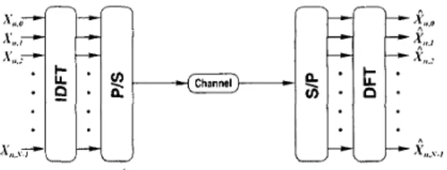
Figure I shows a discrete-time baseband model of an OFDM communication system. where the inverse DIT and the DFT are used in the transmitter and the receiver, respectively
[?I.
In real implementation. the DIT is always replaced by a properly-sized FFT to reduce computation complexity. A mathematical model of the discrete-time OFDM system without channel distortion can be written asX,, = DFT(IDFT(X,,)). ( 1 )
where X,, are the :\- transmitted complex signals that encode the bit stream in the uth symbol and Xl, are the 1Yreceived corn- plex signals. With perfect channel. X,, can be mapped to the orig- inal bit stream. In reality. channel impairments make more signal processing necessary in both the transmitter and the receiver.
Figure 1 : Simplified discrete-time OFDM system model.
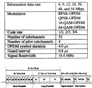
Table I lists several key parameters in the IEEE 802. I I a stan- dard. Figure 2 shows the fundamental frame format of an IEEE
802. I la packet [ I ] . The guard interval duration is 800 ns. which is long enough to cover IS1 in any indoor environment. In the begin- ning of each packet, there are short preamble and long preamble. The receiver exploits these predetermined sequences to conduct channel estimation and achieve proper initialization of several re- ceiver blocks. Among the 5 2 used subchannels, there are 4 pilot subchannels used to assist timinglcarrier tracking tasks during data symbols after the two preambles.
0-7803-6685-9/01/$10.0002001
IEEE
Table 1: Parameters in the lEEE 802.1 l a standard. QPSK-OFDM 16-QAM-OFDM 64-QAh4-OFDM Code
rate
Number of subchannelsI
52Number of pilot subchannels
I
4OFDM svmbol duration
I
4.0 usSignal Bandwidth
I
16.6MHz8+8.18UI
Figure 2: Structure of the IEEE 802.11a packet.
3. RECEIVER DESIGN
In
an
OFDM receiver, in addition to FlT for transforming sig-nals from time domain to frequency domain, channel impairments caused by wireless multi-path fading channels must also be esti- mated and removed or compensated. In the following, several such signal processing techniques used in the proposed receiver will be described.
3.1. Packet Detection
Since a packet starts with the short preamble consisting of 10 iden- tical symbols, a correlator is employed to detect the presence of a packet. This correlator correlates the received signal with itself delayed by 0.8 ps, the length of a short-preamble symbol. This correlation is formulated as
I=O n=O
where z ; are the received signal samples, N is the number of sam- ples in 0.8 /is, and L is the number of symbols in the short pream- ble. Once the correlation value is above a pre-defined threshold for some duration, the receiver announces detection of a packet.
3.2. Coarse Carrier Frequency Acquisition
The carrier frequency offset estimation is again achieved during the short preamble and it is based on a maximum-likelihood esti- mation [3]. The estimated phase drift in a symbol is
L - I A'-1
3.3. Timing Recovery
The IEEE 802.11~1 short preamble has the characteristic of a PN sequence, so timing recovery can be achieved using a matched fil- ter [4]. However, unlike a direct sequence spread spectrum (DSSS) signal, the optimum timing boundary is not where the matched fil- ter output has its maximum. If the timing boundary is chosen at
the position of the
maximum
peakas
shown in Figure 3, an OFDM symbol will suffer from IS1 introduced by the succeeding symbol. Therefore, foran
OFDM symbol with a cyclic prefix, the optimal timing is the interval maximizing the SIR (signal to interference (ISI+ICI) ratio) that is given by [2]where
( 5 ) h ( t ) is the channel impulse response; TO
+
Tg is the chosen start- ing point of the signal interval for FFT, and T9 is the length of the guard interval. However, this method requires a sliding integrator with a maximum-finding circuit after the matched filter, thus a sub- optimal timing location algorithm is proposed. In this algorithm, the largest three peaks of the matched filter outputs are found and the earliest peak is identified. Then, TO is set to the point that precedes this earliest peak by a pre-defined number of samples. Simulation results show that the simplified method recovers the correct timing in most cases.IS1 from the next symbol
t t
1
I ,
a * - -
.
c,
i .2.
Figure 3: Illustration of IS1 from the next symbol when the symbol boundary is set to the maximum peak. The three bars in the bottom illustrates three multi-path signals with different arrival times.
3.4. Channel Estimation
One of the advantages of OFDM is that it is not necessary to use a complicated equalizer to compensate fading caused by the chan- nel. Instead of performing equalization in the time domain, an OFDM receiver usually compensates the channel response in the frequency domain, which requires less computation.
In an IEEE 802.1 l a packet, long preamble carries BPSK mod- ulated signals on the 52 subchannels, which can be used for esti- mating the channel frequency response. Channel estimation and correction can be modeled as [ 5 ]
where X L ~ ~ ~ , is the known kth subchannel signal of the long preamble; 17bng, I: is the received kth subchannel signal during the long preamble. HA. is the channel frequency response on the I = O n = O
kth subchannel; and 11. is AWGN noise on the kth subchannel. Then, the channel frequency response estimation on subchannel
k
is given by(7) In an indoor channel, since the channel impulse response is as- sumed stationary throughout a packet, channel estimation derived in the long preamble can be used to correct the following data sym- bols in the same packet, i.e.,
I i o n g , A HA = -.
-TiLong A
where 1 i . k and f i L , k are the receiver signals before and after chan- nel correction, respectively.
3.5. Tracking
After initial canierhiming synchronization using preambles, there are still two tasks left: to track the remaining carrier frequency drift and sampling clock drift. Figure 4 shows the block diagram of tracking processing in the proposed receiver.
Figure 4: Block diagram of tracking processing.
3.5.1. Carrier Freqiieiicy Tracking
There are four pilot subchannels containing known signals. These pilots can provide information about the phase drift caused by the carrier frequency offset. Since the initial carrier frequency offset has already been acquired during the short preamble, inter-channel interference (ICI) can be neglected. Thus, complex-valued signals on a pilot subchannel rotate with an angular velocity equal to the remaining carrier frequency offset. The pilot subchannel signal phase difference between two consecutive symbols can be used to estimate the carrier frequency offset. The estimated phase error is given by
e f ( ? / ) =
LA?,,
1. - L.?t1-1, A , ( 9 ) Awhere k = -21, -7, 7, and 21. The phase error e r ( " ) is then fed to a phase-locked loop, which consists of four components: a phase-error detector, a loop filter, a numerically controlled oscilla- tor (NCO). and a complex multiplier for phase de-rotation.
3.5.2. Sanlipliiig Clock Tracking
Both carrier frequency offset and sampling clock offset result in phase shift of subchannel signals. Although the phase shift caused by the sampling clock offset is tiny, its influence can not be ne- glected, especially for long packets, high-center-frequency sub- channels, or high-order QAM modulation.
To recover sampling clock offset, interpolation based timing recovery is adopted in the proposed receiver and the timing error is estimated by [6]
et(.) =
([-en,
h -[.en,
1 ) - ( L k n - l + I , - L k n - 1 , I ) , k , 1 k#1(10) where k , 1 = -21, -7, 7, and 21. With four pilot subchan- nels, there exists on the total six terms in the summation. The timing tracking is again performed by a phase-locked loop with a timing-error detector, a loop filter, a timing controller, and
a
digital interpolator.3.5.3. Tracking Consideration
The frequency response of the indoor channel is not always flat. The tracking mechanism has to guarantee that the receiver can cope with drifts in carrier frequency and sampling clock. So the loop parameters in the two tracking phase-locked loops need to be tuned carefully. Moreover, it is likely that pilot subchannels are faded severely by the channel frequency response, especially in channels with long delay spread. In this case, robustness of the pilot subchannels becomes crucial. Fortunately, the channel esti- mation results derived during the long preamble can tell whether a pilot subchannel is robust or not. So, we use the magnitude of a pi- lot subchannel as a robustness indicator when phasehiming errors are calculated.
4. SIMULATION RESULTS
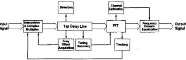
A system made up of an IEEE 802.1 l a transmitter model, an in- door channel model, and the receiver model is built. Whole system performance is evaluated by packet error rate (PER) under differ- ent noise levels and multi-path fading channels with two different delay spreads. Figure 5 shows the complete receiver block diagram and Figure 6 illustrates the simulation model. Note that both car- rier frequency offset and sampling clock offset are set at 20 ppm of the RF frequency and the sampling clock frequency, respectively. The impulse response of the wireless indoor channel model is com-
posed of complex samples whose phase is uniformly distributed and whose magnitude is Rayleigh distributed with exponentially- decaying means [2,7].
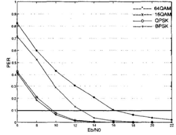
Figure 5 : Block diagram of the proposed receiver. Each transmitted packet consists of IO00 bytes, and the max- imum allowable PER specified in the IEEE 802.1 l a standard is 10%. Figure 7 and 8 show the packet error rates versus Eo/IVO using four data transmission rates and the delay spread of the chan- nel is set to 100 and 150 ns, respectively. The convolutional code used in all cases has a code rate of 1/2. Note that in a typical of- fice environment, the channel delay spread is less than 100 ns. In this case, the proposed receiver can reliably communicate with a
_ _ _ _ _ _ _ _ _ _ _ _ _ _ _ _ _ _ _ _ _ _ _ _ _ _ _ )
Figure 6: Model used in functional simulation.
bit rate up to 36 Mbps (64-QAM). In a larger indoor environment, such as factories, the receiver works best at
a
bit rate up to 12 Mbps (QPSK).Note that for all modulations, the performance is sensitive to the channel delay spread. This is due to the following hvo reasons: First, larger delay spread entails more variations in the channel fre- quency response and more frequency bands with degradation be- yond error correction. Secondly, IS1 increases as the channel delay spread grows, and therefore, it is more likely that the guard inter- val can not cover the multi-path interference. In addition, for the higher-order QAM, more signal energy is needed to achieve the same PER as the channel delay spread increases. In other words, the higher-order QAM is more vulnerable to the increase in chan- nel delay spread.
0 6
~’h\
0 3 0 2 . ._ _.__
EbNOFigure 7: PER performance of the proposed receiver. The channel delay spread is 100 ns.
5. CIRCUIT DESIGN
Digital circuit for the proposed baseband receiver is currently be- ing designed. At first. all processing must be converted to fixed- point arithmetic operations. To minimize the hardware complexity, minimum word length for all signals must be adopted. However. reducing the number of bits used to represent a signal adds quan- tization noise and degrades receiver performance. Therefore, a tradeoff must be made to ensure that the fixed-point-arithmetic re- ceiver architecture causes acceptable PER degradation. With the architecture converted. we must then address the speed and power issues of the receiver circuit.
Figure 8: PER performance of the proposed receiver. The channel delay spread is 150 ns.
6. CONCLUSION
In this paper, an OFDM receiver architecture for high-speed wire- less LAN is proposed. Many techniques, such as channel coding, channel estimation, interpolation, and carrierhming recovery, are adopted to ensure functionality of the proposed receiver in various indoor environments. The system performance is verified and meet the PER specification in the IEEE 802.1 1 a standard using reason- able signal power levels. Future ASIC implementation of IEEE 802. I l a compatible WLAN baseband receivers can be based on the work proposed in this paper.
7. REFERENCES
IEEE 802.1 1, IEEE Staridnrd for Wireless LAN Medium Ac-
cess Control arid Physical Lnyer Specijications, Nov. 1999. van Nee, R. and Prasad, R., OFDM Wireless Multimedia Com- inunications. Artech House. Boston, 2000.
Moose, P. H., “A Technique for Orthogonal Frequency Divi- sion Multiplexing Frequency Offset Correction,” IEEE Trans. Schmidl, T. M. and Cox, D. C., ”Robust Frequency and Tim- ing Synchronization for OFDM,” IEEE Truiu. Corninun., Vol.
45, No. 12,pp. 613-1621, Dec. 1997.
Toso, D., Combelles, P., Galbrun, J., Lauer, L., Penard, P., Roberston, P., Scalise, F., Senn, P. and Soyer, L., ”0.5-
p m CMOS Circuits for Demodulation and Decoding of an OFDM-Based Digital TV Signal Conforming to the European DVB-T Standard,” IEEE J. Solid-state Circuit, Vol. 33, No.
1 I , Nov. 1998.
Gardner E M., ”Interpolation in Digital Modems
-
Part I: Fundamentals.” IEEE Trara. C0171i~1UI?., Vol. 41. No. 3, pp. COITII~ZWZ., Vol. 42, NO. 10, pp. 2908-2914, Oct. 1994.501-507, Mar. 1993.
Saleh, A. A. M. and Valenzuela. R. A., ”A Statistical Model for Indoor Multipath Propagation.” IEEE J. Selected Areas. in
Cortiinui?.. Vol. SAC-5, No. 2, pp.128-137. Feb. 1987.