200 IEEE TRANSACTIONS ON CIRCUITS AND SYSTEMS FOR VIDEO TECHNOLOGY, VOL 6, NO. 2, APRIL 1996
pectrum Multiple-Access
with
and Diversity for Image Transmission
001-
Radio
ultipath Fading Channels
%or-Chin Wang and Po-Rong Chang, Member, IEEE
Abstract- As demand for networked multimedia applications is increasing rapidly, it is important to provide the ubiquitous accessibility for these services in wireless communication envi- ronment. Such access allows users to share novel multimedia applications without any geographical restrictions. In this paper, we investigate the application of the well-known antimultipath spread spectrum code-division multiple access (SS-CDMA) tech- niques to image transmission related to the development of next-generation multimedia wireless local area networks within
a building. SS-CDMA is particularly well suited to a subband coding scheme that divides the image information into multiple parallel data streams using an analysis filter bank, each of which
is multiplied by its unique spreading code. All the product signals are then transmitted at the same time in the same radio channel, even though the total bandwidth of all the signals may exceed the channel bandwidth. Each received signal is independently recovered at the decoder by multiplying its spreading code and all the recovered subbands are then reassembled by a synthesis filter bank into a close reproduction to the original image. A forward error correction (FEC) scheme based on convolutional codes with interleaving is proposed to minimize the effect of bursty channel errors on the picture quality degradation. Better image quality can be achieved by using the predetection diversity combining in order to combat the indoor multipath distortion. In this paper, the image quality of subband image transmission via SS-CDMA in- door fading channels with differential phase shift keying (DPSK)
modulation is evaluated and examined. Simulation results show
that the image peak signal-to-noise (PSNR) ratio is inversely related to a logarithmic function of bit error rate when each subband employs equal protection channel coding.
I . INTRODUCTION
HE future generation of wireless local area networks (WLAN) [ 11-[4] will provide multimedia transport capa- bilities qualitatively similar to those offered by ISDN wireline networks within homes, offices, and intelligent buildings. The concept of wireless indoor communication networks sug- gests itself as a replacement for wired multimedia commu- nication networks in order to avoid expensive installation and relocation cost and to provide portability to various pieces of equipment. Furthermore, the use of radio for indoor multimedia communication in home and office automation systems is an attractive proposition. It would free the users Manuscript received July 14, 1995; revised December 11, 1995. This paper was recommended by Associate Editor H. Gharavi. This work was supported in part by the National Science Council, Taiwan, R.O.C. under contract NSC 85-2221-E009-034.
The authors. are with the Department of Communication Engineering, National Chiao-Tung University, Hsin-Chu, Taiwan, R.O.C.
Publisher Item Identifier S l051-8215(96)03018-2.
from the cords or optical fibers tying them to particular locations within the buildings, thus offering true mobility which is convenient and sometimes even necessary. The deployment of multimedia terminals will support the ever- growing demand for mixed data, voice, and image applications and will be used to connect the portable pen pad and lap-top devices to backbone information resources and computational facilities. The possibility of multimedia service will allow services such as dial-up personal videoconference to any location, image-on-demand services, and portable PC-based applications incorporating with image/voice/data transfer. Im-
age transmission is one of the future potential multimedia services which should be supported with a high wireless transmission bit-rate within a wider allowable bandwidth. Due
to limited radio spectrum, however, only a finite number of radio communication channels can be shared by mobile users. As a result, image data should be compressed before transmission in order to efficiently use each radio channel. C C I l T recommends the international standard H.261 for video transmission at p x 64 kb/s ( p = 1 , 2 , .
.
. ,30), where the intended applications are videophone and videoconference. Recently, transmission of compressed video signal coded by H.261 over a digital cordless telephone system has been experimented with byN.
MacDonald [6]. More recently, transmissions of differential pulse code modulation- (DPCM)- coded and layered images via radio multipath fading channels with TDMA QAM or quatemary differential phase shift key- ing (QDPSK) modulation have been investigated by several researchers [I], [2], [7]-[lo]. However, to the authors’ best knowledge, little work has been done for image transmission by employing the well-known antimultipath spread spectrum techniques except for that reported in [35].In the existing systems, the spread spectrum is used for packet radio to improve the performance in multipath, to make possible coexistence with other systems, and to provide resistance to intentional interference [ 3 ] , [4]. In an in-building environment, the use of spread spectrum can reduce the effects of multipath caused by reflections from the walls and, conse- quently, can increase the mobility of the multimedia terminals within the office or home environment. To further attain the maximum image quality and spectrum efficiency, coded division multiple access (CDMA) techniques incorporating the spread spectrum [E], [16], 1271 are used, where a splitting process is required to divide the image information into a large number of independent data streams, each of which is 1051-8215/96$05.00 0 1996 IEEE
WANG AND CHANG: SPREAD SPECTRUM MULTIPLE-ACCESS WITH DPSK MODULATION AND DIVERSITY
Optical
-
CDMA-
coder OpUCal Optical star
C O d W coupler
-
CDMA-
* -201?5
1 ~N base stationm i
base starion ,-Wireless CDMA- NetworkI
NFiber-optic CDMA Wireless C D M L
Network
-
Networkt
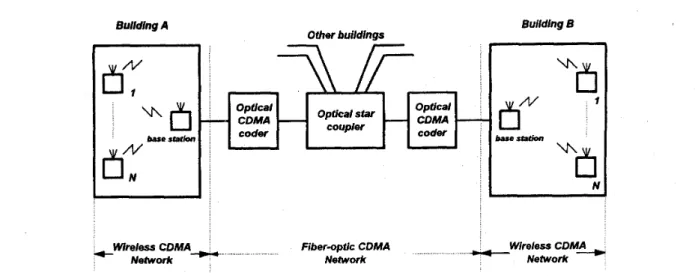
Fig. 1. Overall schematics of wireless CDMA networks internetworking with fiber-optic CDMA networks
transmitted using one of signature (spireading) codes in the CDMA system, and is then spread to full channel bandwidth. In other words, higher data rates are achieved by allocating more than one code to a single image. Moreover, CDMA allows more than one image to be transmitted and be accessed simultaneously and dynamically with no waiting time at the same limited channel bandwidth. This scheme is termed as a multiple code transmission. Wyrwas et al. [l 11 proposed an alternative approach called the multirate CDMA system to increase the transmission data rates. Meanwhile, in this paper, we are only interested in the multiple code CDMA systems.
Another advantage of the image transmission via CDMA indoor fading channels is that the CDMA systems can be in combination with the well-known asynchronous transfer mode (ATM) networks for multimedia services [14]. Each CDMA signature code represents an ATM virtual connection for each image data stream over the air interface.
The image splitting process adopted here is based on sub- band coding [15]-[18], which is one of the less complex encoding algorithms. The principle of subband coding is based on the decomposition of the input image into a number of narrow bands using an analysis filter bank where each band is then decimated, coded, and assigned to its unique signature code separately. In addition to achieving the highest possible image quality within the narrow radio channel bandwidth and maximum spectrum utilization, the input image should be decomposed into a sufficient number of subbands where each band is spread to full channel bandwidth. After transmission, each signal sample is then independently recovered at the receiver by multiplying its code, each with a fixed spreading factor. These recovered subbands are reassembled by the synthesis filter bank into a close approximation to the input image. For dividing the image into subbands, the symmetric short kernel filters [16]-[18] (SSKF’s) are used for filtering. These filters require a very small number of coefficients and are necessary to keep the implementation complexity at a
low level. Moreover, since the synchronous carrier recovery
of conventional SS-CDMA system with coherent phase-shift keying (CPSK) modulation is a difficult task in a multipath
fading environment, it is natural to consider noncoherent differential PSK (DPSK) as a modulation scheme in the SS- CDMA systems [24], [25]. In addition, predetection diversity is employed to combat the multipath fading.
In Section IV, we will discuss the transmission error effects in the subband image via SS-CDMA indoor fading channels. Bit errors in an individual subband will generate error con- tributions at the receiver output within that frequency band. Since the channel error contributions in different subbands are expected to be uncorrelated, the total channel error variance in the recovered image equals the sum of these errors. Moreover, we will show that the total channel error variance is in proportion to the bit error rate when the bit error rate is sufficiently small. This would lead to the image signal-to-noise ratio (SNR) being inversely related to a logarithmic function of the bit error rate. Section V shows computer simulations used to evaluate the image SNR performance of subband image transmission by CDMA systems with perfect power control and without power control.
11. TRANSMISSION OF SUBBAND-CODED IMAGES
OVER IN-BUILDING WIRELESS CDMA LAN’s
Indoor wireless LAN’s are drawing a lot of attention be- cause of their lower cost layout and indoor mobility. A wireless LAN that is compatible to ethernet has been achieved [1]-[3]. More broad-band and multimedia wireless LAN’s that are compatible to ATM-based fiber-optic LAN’s will be developed
[ll], [34]. In the near future, high mobility portable terminals in the wireless LAN’s will be integrated and connected to the broad-band wireline fiber-optic networks. Fig. 1 shows this concept.
One current trend is to build the main links to the home automation system of an intelligent building by using the optical fiber-based ISDN network as a high-speed backbone LAN at 155.5 MB/s x n (n: integer). Branch lines are created using the wireless LAN. From Fig. 1, the portable terminals communicate with the base station via an indoor radio channel. Associated with each base station is a cell or a coverage area, which is the region in the building in which a portable terminal
202 IEEE TRANSACTIONS ON CIRCUITS AND SYSTEMS FOR VIDEO TECHNOLOGY, VOL 6, NO 2, APRIL 1996 $"
p
am pf f f f
I
9
IndoorMobileunits b Reverse LInk a- Base station
or O f
Mobile units
Ease station b Forward Link
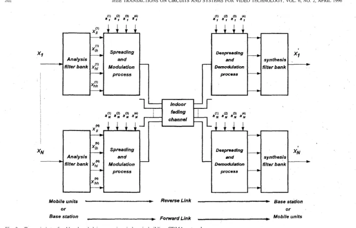
Fig. 2 Transmission of subband coded images via wireless in-building CDMA networks can maintain a dependable link with that base station. In the
multiple-access system for image transmission of interest, the system is assumed to multiplex a set of video signals by applying the CDMA techniques to both wireless and wireline networks. For the wireline backbone fiber optic network, optical CDMA allows more than one image from the base stations of their associated buildings, which technically collide with one another, to transmit and be accessed simultaneously and dynamically with no waiting time at the same wavelength [12], [13]. This fiber optic CDMA image multiple access network can provide system throughput exceeding well over
1 Gb/s, which is much greater than that of a traditional spread spectrum CDMA system via a limited and narrow radio channel. Thus, the total performance of a combination of both wireline and wireless CDMA systems will severely deteriorate as their throughput difference increases.
To overcome this difficulty, a multi-code CDMA technique
is applied to the image transmission in order to increase
its transmission bit rate via the limited radio channels and then reduce the throughput difference. In other words, higher transmission bit rates are achieved by allocating more than one spreading code to each image in order to create more than one virtual transmission channel for that image.
In Fig. 2, there are two possible transmission modes over the indoor radio channel, e.g., forward- and reverse-link trans- missions. The forward-link connection represents the base- to-mobile transmission used to support the video-on-demand (VOD) service, and the reverse-link connection is used to provide the call-in or interactive video program and video
dial tone (VDT) from each portable terminal to the base station. As shown in Figs. 2 and 3, each field in a video se- quence is decomposed into several components (four in Figs. 2 and 3) using a bank of filters (i.e., H ~ ~ ( x I , x ~ ) , H i h ( ~ 1 , ~ 2 ) ,
Hhl(z1, z z ) , H h h ( ~ 1 , ~ 2 ) ) called the analysis filter bank. The lowest frequency component is a lower resolution version of the original scene, and the high frequency components mostly cany information about the contours, edges, and other finer details. These filtered signals are then downsampled to
yield the subband signals. The downsampling following the analysis filter bank reduces the sampling rate of each of the M subband signals to
$
times the input signal sampling rate.As a result, these filters decompose the signal into
M
equally spaced subbands at the same time. For the transmission ofthese subbands at the same time in the same channel, the SS-CDMA multiplexing scheme is particularly well suited to subband coding that divides the image information into multiple parallel data streams, each of which has assigned to it a spreading code in the SS-CDMA system.
Each active subband in the system depicted in Fig. 2 has a unique spreading code which is used for communication to the base station. The base station contains a bank of spread-spectrum transceivers, one for each active subband. For wireless networks, it is possible to use the multi-code CDMA scheme to support higher bit rate video services by increasing the number of spreading codes and their associated decomposed subbands. With a sufficient number of decom- posed subbands or streams, a large spreading factor can be used and yet the total signal can fit within the narrow wireless
WANG AND CHANG: SPREAD SPECTRUM MULTIPLE-ACCESS WITH DPSK MODULATION AND DIVERSITY 203
downsampling subband spreading ai codes
I
-
a1 upsampling a..I
\
U I Synthesis filters If,
-
Despreading process -+ Fig. 3. frequency and M = 4.Transmission of subband-coded images via SS-CDMA indoor fading channels where a t ' s denote the spreading codes, f C denotes the carrier
channel bandwidth and also provide the high transmission rate for the fiber optic CDMA network. In other words, an image of rate M T b is disassembled (de-multiplexed) into M subsequences each of rate T b . Each subsequence is transmitted using one of M spreading codes with a fixed relatively large spreading factor. Thus, the M subsequences can be transmitted at the same time in the same channel, without crosstalk. Each subsequence is independently recovered at the receiver by multiplying by its unique spreading code and integrating over the sequence length. At the receiver, the M received subsequences are then decoded, upsampled, and reassembled (multiplexed) by the synthesis filter bank into a close approximation to the input scene.
In this paper, the focus is on intra-field subband coding, and the exploitation of temporal correlation can be carried out by a 3-D subband system [20], which consists of temporal, horizontal, and vertical filterings. Undoubtedly, the SS-CDMA system can be applied to the 3-D subband system directly. However, the use of intra-field coding is motivated by the goal to keep the decoder cost low. The implementation is relatively simple since frame stores and motion detectiodestimation hardware is not required. Each field in the video sequence is represented by using 2-D subband coding ['l5].
A. Spread Spectrum CDMA Model with DPSK Modulation
The spread spectrum CDMA technique is able to achieve the high transmission bit-rate services of more than one image via the same limited radio band within a building simultaneously. However, the synchronous carrier recovery of the SS-CDMA with BPSK modulation is a difficult task in a multipath fading channel. To resolve the phase ambiguity in the recovery, a differentially encoded PSK (DPSK) is used to encode the binary digit not by the absolute phase of the carrier but by the phase change between successive bits. For N images
transmitted at N different positions, each of them is divided
into M subband images which have their own spreading P N codes. The transmitting DPSK signal s k l
( t )
of the j t h subbandof the kth image is expressed as
s k l ( t ) = f i a t ) ( t ) @ ) ( t ) cos(w,t
+
g k g ) (1) wherea t ' ( t )
andb t ) ( t )
denote a spreading code and a differentially encoded data signal for the jth subband of the kth image, respectively, P is the signal power, Okl is arandom phase, uniformly distributed between 0 and 27r, and
1 5
j5
M , 15
k5
Na = - - 0 0
M
( 3 )
a = - m
where b t l E {+1, -1} denotes the differentially encoded bit of subband j of image k in the ith time interval, $'(t) is an infinite random signature code sequence assigned to the j t h subband of image
IC
with each chipa t !
independent and equiprobably distributed on {+1, -l}, and IIT(.) is the unit pulse function of duration T , defined by(4) The duration of each data bit is T , while the duration of each chip in the spreading code signal is T,. As a result, the number of chips per bit is N , =
E,
where N , is an integer and usually called the length of the spreading sequence. In mathematical sense, the DPSK encoding scheme selects the current encoded bit b k j based on the information bit d t ! and the previous encoded bit b t ! - l according to the logic functionb(') k,a = &) k,a b ( 3 ) k , a - l ( 5 ) where @ represents the exclusive OR operation.
204 IEEE TRANSACTIONS ON CIRCUITS AND SYSTEMS FOR VIDEO TECHNOLOGY, VOL. 6, NO. 2, APRIL 1996
RF
to IF Matched DPSK Diversity Hard outputDecision
-
Filter
-
&mod-
Circuit---
-
B. Statistical Channel Impulse Response Models for Indoor Radio Channels
The multipath fading indoor channels are assumed to be discrete and time-invariant with channel impulse response for the gth subband of the kth image given by 131,
1-51, [191, 1241
L k )
h k j ( t ) P Z k j S ( t - T l k j ) e 3 4 ’ k 3 (6) 1=1
where p l k j is the Zth Rayleigh distributed random path gain, 4 l k j is the Zth random path phase, uniformly distributed between zero and 27r, and 71k3 is the lth uniformly distributed
random delay ranging from zero to one data bit period, T . S ( t ) represents the unit impulse function. LkJ denotes the
number of multipaths for subband J of image k which may
be either fixed or a random variable. Note that the channel parameters / 3 1 k j , 7 Z k J , and $i51kj are actually randomly time-
varying functions. However, the rate of their variations in an indoor radio environment is very slow compared to usual signaling rates. Thus, these parameters can be treated as virtually time-invariant random variables which do not vary significantly over two consecutive bit intervals. In addition, it should be mentioned that these channel parameters vary with the transmitter-receiver distance. For example, the mean amplitude of each path gain is generated from a log-normal distribution which depends on the distance. Therefore, it could be concluded that P l k j = P l k l = p l k , 7 1 k 3 = 7 l k l = 7 & ,
$ l k j = h k l = ( P l k , L k j = L k l = L k and h k j ( t ) = hk(t) for 1
5
j5
M
and 15
k5
N since all the subbands in the same image are transmitted over the same propagation environment between the transmitter and receiver, and then would have identical channel characteristics.In addition, Kavehrad and McLane [3], [24] showed that the maximum value of L k can be derived based on the minimum
resolution of discrete-sequence spread-spectrum signals. The maximum number of resolved paths for a maximum multipath delay spread of
Tk
seconds is found by(7) where
I
.
I
is the function which returns the largest integer less than or equal to its argument. Moreover, TA should beless than T , the data bit interval, in order to avoid intersymbol interference. In a typical indoor radio channel, utilizing the FEC allocated 25 MHz bandwidth (T, = 40 ns), the number of paths for different multipath delay spreads are L y = 1
for TA = 25 ns or Lrax = 4 for T$ = 150 ns. Generally, the number of paths, L k is a random variable which varies
uniformly between unity and the maximum value given in
(7). Recently, a ray cluster model of the indoor radio channel, which fits measurements well, has been suggested [19]. In this model, the received signals arrive in cluster.
C. DPSK Demodulation with Predetection Diversity
The effect of transmitting M x N subbands is as if there
were M N users to be transmitted. A receiver consisting of
M DPSK SS-CDMA demodulators may be used to recover
a desired image where each demodulator is trying to match its corresponding subband belonging to that image. The M recovered subbands are then upsampled and reassembled by synthesis filters into a close approximation to the desired image. However, to combat the multipath fading distortion and achieve better performance, a receiver with diversity combining is needed [241, [251, [291.
The commonly-used diversity combining techniques are selection diversity and predetection diversity. In this paper, we consider the predetection diversity. Predetection diversity for coherent PSK reception is called the maximal ratio combining (MRC). However, it should have perfect knowledge of the path gains and phases in the indoor radio channels. Unlike coherent PSK with MRC, DPSK with predetection combining can be implemented without estimation of the path gains and delays; it is required only that the phases of the Rayleigh-fading components do not change over the duration of two adjacent bits (slow fading). The predetection diversity for DPSK is also called equal gain combining (EGC). The predetection diversity is obtained either by using multiple antennas, or by resolving multipath, or both. Diversity obtained from resolving multipath is called spread-spectrum diversity or inherent diversity, while that obtained from multiple antennas is called antenna or external diversity. Fig. 4 for predetection combining shows only spread-spectrum diversity since this is the simplest to implement. The receiver contains a filter matched to the spreading code waveform of the reference user, followed by a DPSK demodulator and an integrator acting as an EGC diversity circuit The demodulated signal is integrated prior to detection over a time interval whose length depends on the delay spread.
The received signal at the input to the matched-filter in the receiver is given by
WANG AND CHANG: SPREAD SPECTRUM MULTIPLE-ACCESS WITH DPSK MODULATION AND DIVERSITY 205 N M L k j =
mx
c
C P 1 k l a f ) ( t - 7 1 k 3 ) b k ) ( t - 7 1 k l ) k=l J=I 1=1 x cos(wct+
( P 1 k l )+
n ( t ) ( P l k J = --WC7lkJ+
4 l k J+
e l k 3 (8)where s”k3
( t )
is the complex envelope of s k l ( t ) , Re{.} denotes the real part of complex number, andn(t)
is a white Gaussian noise with two-sided power spectral density No/2.For simplified analysis, the first subband of the first image is chosen as the reference user for calculating the probability of error of its data symbol biti. The receiver is able to coherently recover the carrier phase pZll and 7,11 locking
to the ith path as a reference path between the transmitter
of reference subband and its corresponding receiver [24]. All other paths constitute interference. That is, we assume without loss of generality that yzll = 0 and T , ~ ~ = 0. According to the concept of Kavehred and Ramamurthi [24], the complex envelope of the matched-filter output at the sampling instant
(t
= T ) is denoted by zo and can be expressed as a form in terms ofb t L l
and bt,b ZO = P ( b k , - l ? ( 3 ) bk,$ ( 3 ) 1I
jI
M , 1I
k5
N )+
(710+
jvo) k = 2 j=l 1=1 x Rkj, 11 ( T l k l )+
b$hl, 11 ( T l k lI]
+
j P l k , 4 l l t l k l ) x [bgLIRklrll(~lkl)+
b g & , l l ( T l k J ) ] }+
(ro
+
j.0) (9)where
b t L 1
and are the previous and current data bit for the j t h subband of the kth image, respectively, and F ( . ) denotes the first four terms of (9) and is a function of a set of data bits, bf), andbtb,
15
j5
M , 15
k 5 N .In (9), &,,11(~) and & j , 1 1 ( ~ ) are the well known continu-
ous time partial cross-correlation functions of the regenerated code, a y ) ( t ) , and a delayed version of the interfering codes, a F ) ( t - 7 ) . They are defined as
T
& j , l l ( T ) =
s,
a p ( t
- T).!”(t) d t . (10) The noise samples ~0 and vo are independent, zero-meanGaussian random variables with identical variances U’ (= N O T ) and given as
where nc(t) and
n,(t)
are the in-phase and the quadrature components of n(t), respectively.Since the fading of indoor radio channel is slow compared to the data rate, the corresponding complex envelope at the previous sampling instant, denoted by 2-1, differs from zo
only in the data bits, and in the additive Gaussian noise samples. Hence, x-1 has the same expression as that of zo
but involves a set of data bits and Gaussian noise samples at the previous sampling point and is given by
z-1 = F ( b t L 2 ,
bt),;
15
j5
M , 15
k5
N )+
(rl-1+
jv-1). (12)Therefore, the output of the DPSK demodulator at the sampling instant is written as
<
= R e { z d l } (13) where*
denotes complex conjugate. When there is no diver- sity, [ is the decision variable. The estimate;!:?
of the databit bit; is determined based on the hard decision value
A bit error occurs if
6iti
#
b i t i .In (9), the first term represents the desired subband to be detected and it has average power, (/3,211PT2/2), for a fixed PZ1l. The second term is called the interpath interference or self-interference induced by the desired subband on itself because of multipath and the sidelobes of the autocorrelation function of the spreading code of reference subband. The interuser interference for the desired subband can be divided into two parts. The third term in (9) is the first part, called‘ the intra-image interference, which is generated from the (L1,
+
LI3+
. . .+
L 1 ~ ) inter-subbands in the same image corresponding to the desired subband. The fourth term in (9) is the second part, called the inter-image interference, which is generated from the ( L z l + .. .
+
L Z M+
L31+ .. .
+
L ~ M+
...
+
L N M ) subbands in the ( N - 1) inter-images. Finally, vo + j m is an additive complexed-valued Gaussian noise with-206 IEEE TRANSACTIONS ON CIRCUITS AND SYSTEMS FOR VIDEO TECHNOLOGY, VOL. 6, NO. 2, APRIL 1996
zero mean and variance
y.
Note that all the interference terms can also come from the preceding bit,btL1,
in addition to the current bit, b$.From the above discussion, it is clear that each additional path adds extra interference to the reference user. If there are ( K - 1) interfering users, each of whose signals arrive via L
paths, the effect is as if there were ( K - l ) L interfering users. However, the total number of interference terms should be
NI
= ( K - l ) L+
L - 1 when the reference user is alsotransmitted via L paths to create ( L - 1) self-interference
terms. For the subband coded images, the total number of interference terms to a reference subband is N I = M N L - 1
when L k , = L for 1
5
k5
N and 15
j5
M .With predetection combining diversity of order h f d , the new decision variable is the weighted sum of i b f d DPSK demodulator outputs resulted from the Md diversity chan- nels or combined paths. We refer to the i b f d paths involved
in the combining as the combined paths. The weights are taken equal to the corresponding complexed-valued channel gain /3lk, exp(--jqk,). The effect of this multiplication is
to compensate for the phase shift in the channel and to weigh the signal by a factor that is proportional to the signal strength. A reason for using DPSK is that the time variations in the channel parameters are sufficiently slow so that the channel phase shifts (7&) do not change appreciably over
two consecutive signaling intervals (DPSK detection). Hence, the channel parameters {,& exp(-j7lk,)} are assumed to
remain constant over two successive signaling intervals. Under that condition, the DPSK with predetection combining can be implemented without estimation of the channel parameters. This predetection combining scheme is also called the equal gain combining (EGC). In practice, its decision variable, &GC,
is obtained by sampling the DPSK demodulated signal at the appropriate instants within a specific time interval and adding the samples. The EGC decision variable, &GC, is thus written
as
~ E G C
m=l m = l
(15) where
tm
is the DPSK demodulated signal at the mth sam- pling instant corresponding to the mth diversity channel or combined path, 1 0 , ~ and 1 - 1 , ~ denote the total interferences to the desired data bits and bit?, at the mth sampling point respectively, and(vzm
+
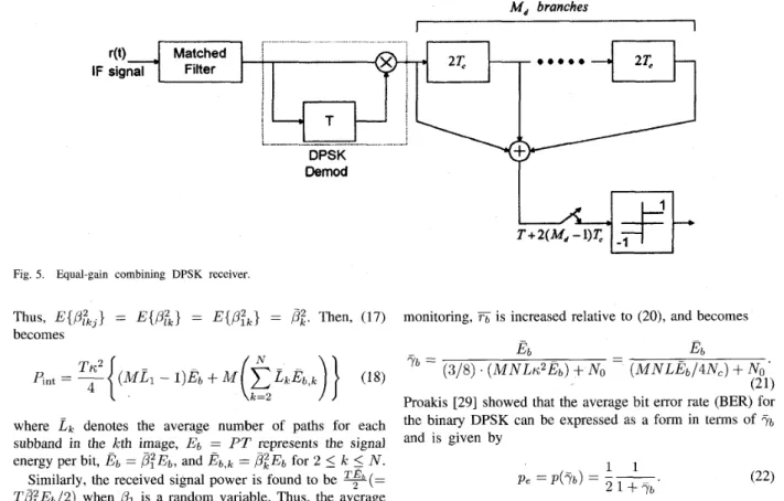
-juEm) are the complex-valued additive white Gaussian noise (AWGN) noises at the mth sampling point for bit?, i = - 1 , O . The above diversity scheme is termed as an EGC time diversity where each time slot represents a diversity channel. The structure of an equal- gain combining DPSK receiver i s shown in Fig. 5, where thenumber of branches (or the number of combined paths), Md, is a parameter less than or equal to (L11/2).
Eng and Milstein [25] showed that the branch spacing of diversity i s 2T, (instead of T, as for the coherent PSK
receiver) because the matched filter response to adjacent paths are correlated and are uncorrelated for nonadjacent paths. Therefore, to maximize the benefits of diversity for a given number of branches, only every other path is combined. In (15),
tm
corresponds to the mth branch of the receiver. The sampling times of the receiver are (i+
l)T+
2(Md - l)Tc where i represents the time index of data bits. For example, to detect the zeroth data bit bit;, the sampling time would be T+
2(Md - l)Tc; the “T’ term is the usually matchedfilter sampling time and the “ 2 ( i b f d - i)T,” term is from the
combining of (Md - 1) additional combined paths. By using multiple antennas, the highest possible order of diversity can be increased to ( h f d ) m a x = Lant
.
(L11/2) where Lant is the number of antennas. Moreover, in a practical implementation, the decision variable &GC is approximated by integrating theDPSK demodulator output over an interval with a duration of
(a(&&
- l)Tc), thereby replacinga
sum of samples by a continuous-time integration. This approximation avoids the need for the time-synchronization to each of the different path signals of the reference subband (user). A hard decision is made on &GC in order to detect bit;.D. Average Bit Error Probability
For the simplified derivation of the bit error probability, the Gaussian assumption is to take all the self-interference, intra-image interference, and inter-image interference terms as Gaussian noise. To calculate the total power of the interference terms, one should evaluate a term like
where b t Y 1 and b k b are independent bipolar random vari-
ables. Pursley [26] showed that lc2 is a constant which has
the value 2/3Nc. Since the interference terms in (9) are all mutually independent, the total interference power becomes p. Int - - interference . power = Re{1*1)
(17)
where I is the total interference to the desired bit bit; and contains the second, third, and fourth terms of (9). It is shown
1 5 j
5
M and 15
k 5N.
Furthermore, assume that the path gains for all the subbands in the same image are independently identically distributed (i.i.d.) random variables. in 11-B that p l k , = p l k l = p l k and L k , = L k l = L k forWANG AND CHANG: SPREAD SPECTRUM MULTIPLE-ACCESS WITH DPSK MODULATION AND DIVERSITY - 207 Md branches
I
I
DemodFig. 5. Equal-gain combining DPSK receiver.
Thus, becomes
= E{P&} = E { p f k } =
pz.
Then, (17)where L k denotes the average number of paths for each subband in the kth image, Eb = PT represents the signal energy per bit, E 6 = ,@E,,, and &,k = P ~ E I , for 2
5
k5
N .Similarly, the received signal power is found to be ?(= T,@E6/2) when
,& is a random variable. Thus, the average
value of half the signal-to-noise plus interference power ratio becomes* (19) E 6
K 2
[(ME1
- 1)E6+
hf(xc=2 z k E 6 , k ) ]+
NO76
=At a reference receiver, the received power from the nearer transmitter can be much bigger than that of the farther trans- mitter. This is called the near-far problem. Ideally, the re- ceived signals are intended to be received with equal power but actually have different power when received. A number of power control mechanisms [27], [28] are trying to compensate for the difference and then keep the received average powers almost equal. This is equivalent to placing all the images
on an equidistance contour around the reference receiver. Thus, all the path gains p k ’ s become i.i.d. random variables. Therefore, after applying a perfect power control to the SS- CDMA system, each image would contribute the identical received energy per bit, i.e., E b , k = E 6 for 1
5 IC 5
N .Moreover, L k , 1
5
kL:
N are assumed to be identical andequal to L. Thus, for a large MNL,Tb would become
monitoring, 6 is increased relative to (20), and becomes
Proakis [29] showed that the average bit error rate (BER) for the binary DPSK can be expressed as a form in terms of
7 b
and is given by
When predetection diversity of order
A&
is used, it can be shown [29] that the bit error rate for the DPSK with EGC combining is written as where 1 b ; = -i!
M d - l - i n = OIn (23), the quantity Fy.= is the average signal-to-noise ratio per combined path, with the sum of interference and Gaussian noise. It can be shown that the value of
rc
may be identical to either (20) or (21) and is given byE b
(2cuMNLE313N,)+Nu
,
for general video applicationsfor video telephone
(25)
( M N L E b / 4 N c )+No
’
r c =
where a is a video activity factor of a specific video appli- cation. For
approximated by the expression
>>
1, the bit error probability in (23) can be Moreover, for the application of video telephone, the interfer-ence term can be reduced by a factor of 8/3 because the video activity factor of video telephone would be often equal to its telephone conversations. Thus with video and voice activity
208 IEEE TRANSACTIONS ON CIRCUITS AND SYSTEMS FOR VIDEO TECHNOLOGY, VOL 6, NO 2, APRIL 1996
111. LOW-COMPLEXITY SUBBAND CODING USING
SEPARABLE EXACT RECONSTRUCTION FILTER BANKS
The most computationally efficient approach to splitting and merging subband images results from using separable filters. The separable subband decomposition is performed in two stages using l-D filters that process the data along the rows and columns of the image data array. The input signal z is
first applied to horizontal filters Hl(z1) (lowpass) and Hh(zl) (highpass), and horizontally downsampled to get the signals zz
and x h , respectively. In the second stage of the decomposition, each of the signals zl and xh is applied to the two vertical filters Hl(z2) (lowpass) and Hh (z2) (highpass), and vertically downsampled to get the subband signals 211, xlh, z h l , and z h h .
For the purpose of reconstruction, the signals are merged by
upsampling and filtering using the synthesis filters. The vertical synthesis filters are denoted by G ( ( z 2 ) (lowpass) and Gh(z2)
(highpass), and the horizontal synthesis filters are denoted by Gl(z1) (lowpass) and Gh(z1) (highpass).
According to the separability characteristics of HZy(zl, 2 2 )
and G,,(zl, z2), the 2-D filtering can be implemented as a product of l-D filtering operations [15]
Hz,(z1,z2) = Hz(z1)Hy(z2) (27) Gzy(%Z2) = Gr(Zl)Gy(Z2) (28)
where x and y denote 1 (lowpass) or h (highpass).
Moreover, it is shown that the 2-D exact reconstruction filters for Hzy(zl, z2) and G,,(xl, x2) can be developed in
terms of 1-D exact reconstruction filters. In designing l-D exact reconstruction filters, we should focus on an analysis into a two-channel system. The analysis filter bank splits the input signal into two-channel signals by processing it with a lowpass filter H l ( z ) in one path and with a highpass filter H h ( z ) in
the other. The filtered signals uo and u1 are downsampled by a factor of two to obtain the subband signals z1 and zh.
In a back-to-back connection, these signals are upsampled and processed by the synthesis filters with transfer functions Gl(z) and G h ( z ) . In other words, every second sample has been
discarded by the downsampling and has been reinserted as a zero-valued sample by the upsampling. The aliasing distortion in the reconstruction can be removed if the synthesis filters are defined as
G i ( z ) = H h ( - z )
(29) Quadrature mirror filters [21] (QMF’s) have been proposed and widely used as analysis and synthesis filters in subband coding of images. However, [lX] showed that QMF’s do not permit reconstruction to be exact, although the reconstruction error can be made very small by using long tap filters. For video and digital image applications, use of such long tap filters, while not providing any significant coding gain, may increase the hardware complexity. Since the processing of video signals in wireless channels involves high sampling rates, it is very desirable to keep the filter bank complexity low. SSKF’s have been considered as the low-complexity subband decomposition and reconstruction filter pairs because of the simplicity in implementation [17]. The SSKF’s are
{
G ~ ( x ) = -Hi(-%).the symmetric short filters which are obtained by factoring a product filter, P ( z ) = H l ( z ) H h ( - z ) into linear phase
components. Le Gall et al. [17] showed an example of the
lowpass and highpass analysis filters given by
H[(Z) = 4(-1+ 1 32-1
+
3z-2 - 2 - 3 )I&(%)
= i(1- 32-1 f 3 K 2 - z - 3 ) . (30){
The four-tap filters of (30) are implementable using a small
number of shift and add operations. The use of general multi- pliers is avoided. This leads to a simple and computationally efficient subband coding implementation. These filters are able to decompose the signal into two equally spaced subbands at a time, and produce visually pleasant and smooth outputs. Note that the decomposition of the input image can be extended to more than four bands by repeating the separability process to each subband image in a tree-structured manner. An alternative method of dividing a signal into a number of equally spaced subbands is the generalized quadrature mirror filters (GQMF’s)
PI.
A. PCM/DPCM Coding of Subband Signals
To achieve maximum compression with high image fidelity, the subbands have to be encoded on a perceptual basis by following proper coding strategy. The subband signal carrying the lowest frequency information usually has a high degree of spatial correlation that is suitable for coding using either predictive techniques such as DPCM or transform coding using discrete cosine transform [16], [22]. Since the baseband contains the most information, this band is quantized as accurately as possible. The high frequkncy subbands contain edge and contour information. These subband signals can be directly quantized by coarse quantizers since the noise produced by quantizing higher bands with a few levels can easily be tolerated by the human eye and then PCM encoded in the spatial domain. A large fraction of the quantized data in the high frequency band signals consists of zero samples and these signals are therefore well suited for runlength encoding. The baseband has a histogram that is similar to the original image with high pixel-to-pixel correlation. Due to this high correlation, the DPCM encoder is chosen to code the subband. The pixel configuration for the 2-D prediction is shown in Fig. 5. The predicted value is given by
?A = b X B f C X c f d X D (3 1) where X B , X C , and are previously reconstructed pixels, and 2~ is the prediction of the present pixel. The weighting factors, b , c, and d are chosen to be 0.5, 0.25, and 0.25, respectively. The prediction error signal is quantized by a symmetric nonuniform quantizer.
An optimal approach in the minimum mean square sense is to design a quantizer which matches the probability density function of the input signals (close to generalized Gaussian or Laplacian probability density function). This optimal quantizer is known as Lloyd-Max quantizer. However, Gharavi and Tabatabai [16] showed that such a quantizer is not suitable for encoding the higher frequency band signals. This is mainly due to the existence of picture noise which manifests itself as a
WANG AND CHANG SPREAD SPECTRUM MULTIPLE-ACCESS WITH DPSK MODULATION AND DIVERSITY 209 C D
v
\/ Previous linev
\/ B A Present line/\
Present pixelFig. 6 . Configuration of pixels used for prediction.
low level signal within these bands, and would result in a fine quantization of the noise. To circumvent this problem, they proposed a highly efficient nonuniform symmetric quantizers with a center dead zone, d, to quantize the high bands. The dead zone is used to eliminate the picture noise. The input values in the active region are then uniformly quantized to L
levels. Moreover, it contains a saturation value, Y , for signals whose magnitude are above a given threshold, t. Meanwhile, the quantized high bands are observed to have a large number of connected areas of zeros. Therefore, run-length coding techniques are implemented as 1-D codes for this purpose. In order to achieve a higher compression ratio, Le Gall et al. [17] extended the above method by using arithmetic coding in combination with DPCM coding of lower band and PCM coding of higher band signals.
When aiming for a constant bit rate for each subband via the SS-CDMA system, it is convenient to assume that each subband is encoded into a constant number of bits and its output rate is monitored on a line-by-line basis. The instantaneous bit rate of the specific line being encoded is compared against its targeted rate, and its dead zone is appropriately increased, decreased, or maintained. In addition, a buffer is used to smooth out the variations in the rate. Then the bit rate is kept constant for each subband. More details about the bit rate control can be found in [22].
B. Error Protection Strategies
Among various forward error correction (FEC) schemes, the convolutional code with interleaving is one of the useful codes for correcting both bursty and random errors in the SS- CDMA multipath fading channels. Decoding algorithms play an essential role in the performance of a convolutional code. The well-known Viterbi algorithm is an effective maximum likelihood decoding algorithm for convolutional codes. We consider a SS-CDMA system in which a convolutional en- coder with a code rate Re is used in conjunction with hard decision Viterbi decoding. Although it is possible to obtain better performance with soft-decisions, hard-decision decoding is commonly used in wireless communications because it is simpler to implement. Moreover, Lin and Costello [ 2 3 ] addressed the problem of constructing good codes for use with the Viterbi algorithm. Once the desired code rate has been selected, the bit error probability is minimized when the free distance of the code, dfree, is chosen as large as possible. One of the good codes is a binary (2, 1, 6) code which has
Re
=f ,
dfree = 10 and asymptotic coding gain of 3.98 dB.In this paper, we used the convolutional codes to improve the BER performance shown in (23). Reference [29] indicated that there is no exact closed form for the BER of the DPSK receiver with convolutional codes and equal-gain combining diversity for Rayleigh fading channels. However, its BER is upperbounded by the expression
Pe
5
@(Ycode, dfree) (32)where =
R,Tc.
Note that the expression of @(.) depends on the types of diversity combining decoding, i.e., hard- decision or soft-decision decoding.IV. IMAGE QUALITY EVALUATION FOR CDMA SUBBAND
IMAGE mANSMISSION VIA INDOOR FADING CHANNELS
As discussed in Section 111, there are two encoding tech- niques for subband images. The baseband is encoded using DPCM, and higher bands are PCM encoded. Usually the reconstructed output signal y ( n ) includes an input signal, x(n), and the effects of both quantization error, q(n), and total CDMA interference and noise, e(.). The total reconstruction error variance for the PCM encoding is defined by
(33) where x is the input signal and y is the reconstructed output signal.
R. Steele et al. [9] showed that the o:,PCM can be written as
d , P C M = O;,PCM
+
&,PCM f c2,PCM (34) where a%,pCM represents the quantization error variance,oz,pCM is the mean-square error contribution due solely to channel errors, and finally, the quantity & P C M represents a mutual error term. They also found that the transmission error variance in companded PCM over Rayleigh fading channels when the PCM bit stream is scrambled (or interleaved) prior to its transmission can be expressed in terms of the bit error probability, p,, and is given by
R
2 , P C M = CTJP3, (35)
J = 1
where R is the number of bits used to represent the quantizer output. The term T3 is
210 IEEE TRANSACTIONS ON CIRCUITS AND SYSTEMS FOR VIDEO TECHNOLOGY, VOL 6, NO. 2 , APRIL 1996
and the quantity
S,
is given in[9].
Note that by the process of interleaving, the burst errors that occurs in Rayleigh fading channels are randomized because bursty bit errors are much more difficult to correct than random bit errors.Jayant and No11 [30] showed, moreover, that the cross-
correlation between quantization and channel errors is nearly equal to zero if the quantizer characteristics are close to that of an optimum quantizer. Thus, a m , p c ~ = 0. However, for simplified analysis, they also proposed an alternative formulation which is quite similar to Steele et al.'s expression and can be written as
and
where E: is called the channel performance factor, and <j
are channel coefficients that reflect the effects on 0," of the
quantizer characteristics, the chosen binary code and the source statistics. For example,
C1
= 2.55, C2 = 4.97, <3 = 6.91 when natural binary code is chosen and a nonuniform quantizer is used. The bit error probability for CDMA indoor fading channel without or with convolutional channel coding is shown in Section 11. Here, we would apply Jayant and Noli's formulation to the image quality analysis via CDMA channels.From (34) and (37), it yields
(39)
where is the PCM quantizer performance factor whose
quantizer characteristics are close to that of an optimum quantizer.
A. Transmission Errors in DPCM over CDMA Fading Channels
The performance analysis of 2-D DPCM image transmission over fading channels was first discussed in [lo] by Daut and Modestino who showed that the total reconstruction error variance of the DPCM image based on a 2-D separable second order Gauss-Markov autoregressive (AR) random field model in the presence of fading bursty and AWGN random channel errors can be expressed as the sum of three separate components
g?,DPCM = O;,DPCM
+
O&,DPCM+
a?,DPCM --
(€:,mm
+
&,DPCM+
t,2,DpcM)a,2 (40)where
01
is the prediction error variance, and~
i
denote the DPCM quantizer and channel performance,
~
~
~
~
factors respectively, and
~
k
represents the normalized,
~
~
~
~
mutual error term. By the assumption of equal bit error rate for each bit in the R-bit quantizer, in (40), the DPCM channel performance factor can be written as
1
L-1 xi
(1 - P e )(
T)
L 2 - 1+
P, 1=0 ( L - 1 - 2 1 y p l 2 3=3where L is the number of quantization levels, A is the normalized step size for optimum uniform quantizer,
&
is the j th DPCM channel coefficient, pl denotes the probability that the input signal falls in the lth quantization interval, andp1 and p 2 are the correlation coefficients in the 2-D second order AR model. The typical values for the outdoor scene are
p1 = 0.957 and p2 = 0.967 [lo].
can be approx- is called the power transfer factor of the decoder filter of the
DPCM. Moreover, the quantity has been found to be
negligible compared to
of (40) reduces to
Jayant and No11 [30] showed that
imately expressed as: x ~2 t= ye:, ~where y , ~ ~ ~
and
~ z , ~ ~ ~ ~ .
Thus,where G p is the prediction gain which is defined as the ratio between the input signal variance and the prediction error variance.
Comparing (42) with (39), it may be found that the quanti- zation noise contribution in DPCM is smaller than in PCM by a factor G p ; and the channel error contribution in DPCM is smaller than in PCM by a factor
%,
provided thatis equal to Note that the ratio between and
ct,DpcM is equal to unity for generalized Gaussian images or for Laplacian images [30].
B. Analysis of CDMA Channel Errors in Subband Images
For the transmission of nilsubbands via the CDMA fading
channels, is treated as the reconstruction error vari-
ance for base band, azl, and I T : , , ~ ~ ' S are used to characterize
the reconstruction error variances for higher bands, a:,
,
k>
1.In other words, a,"k represents the error variance of the
kth
received subband in the reference image via a virtual connection over the air interface created by its corresponding kth spreading code. Furthermore, [31] and [32] showed that the reconstruction error variance of an image via nil parallel independent virtual channels can be obtained by performing a weighted sum of total subband reconstruction error variances, that isM
dnage
= Q d k (43)k = l
where the weighting value for the kth subband is specified by
where Gk(w1, w2) is the transfer function of the synthesis
filter for the kth subband. However, for the case of separable reconstruction filters and M = 4, the weighting values are
WANG AND CHANG: SPREAD SPECTRUM MULTIPLE-ACCESS WITH DPSK MODULATION AND DIVERSITY 211
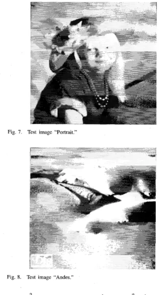
Fig. 7. Test image “Portrait.”
Fig. 8. Test image “Andes.”
Q l l = Q p , Q l h = Qhl = Q h Q l , and Qhh =
QE,
where Q i andah are the power transfer factors for lowpass and highpass synthesis filters, respectively. Cheong et al. [31] found that both QMF and orthonormal wavelets have a value nearly equal to unity (cui = Q h M 0.9999), and SSKF has low values
(QZ = 0.75 and ah = 0.359375). This implies that SSKF achieves much smaller image reconstruction error variance than both QMF and orthonormal wavelet.
Moreover, total quantization error variance in (43), gtq,
is assumed to be much smaller than the total channel error variance, a&, and then is negligible for the derivation of the image signal-to-noise ratio. Therefore, from (39), (42), and (43), it yields
In (45), each subband may be protected by unequal error correction (UEC) strategy using rate compatible punctured convolutional codes (RCPC). From ( 4 3 , the signal-to-noise
-A- Andesimage
+
theoretie M error 1E-1 1 E-3 1 FA - . I 1 I I 0 10 P 30 U ) 50Fig. 9. The bit error rates of the “Portrait” and “Andes” images placed on
an equidistance contour via SS-CDMA indoor fading channels with EGC combining and Md = 4. 1E-1 1 E-2 1 Andesimage 1 E-3 1 E 4 1 E-5 0 10 20 30 40 50
Fig. 10. The hit error rates of the “Portrait” and “Andes” images placed on
an equidistance contour via SS-CDMA indoor fading channels with a (2, 1, 6) convolutional code and EGC combining of M,j = 4.
ratio of the output image [30] becomes
/ M \
where
x
and y denote the input and output gray values, respectively.For simplified analysis, it may be assumed that the bit error probabilities of the subbands in the same image are identical because each of them has the same interpath, intra-image,
and inter-image subband interferences and AWGN noise over
the CDMA channel when each subband employs equal error protection channel coding. If pr and R are sufficiently small,
the channel contribytes to C : only through single errors. Thus, x C f p e (or z (:pe) for the kth subband, k 2 2 (or the
212 IEEE TRANSACTIONS ON CIRCUITS AND SYSTEMS FOR VIDEO TECHNOLOGY, VOL. 6, NO. 2, APRIL 1996
+
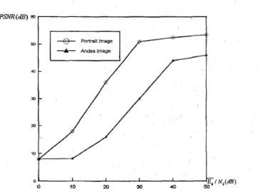
PortraitimageFig. 11. PSNR performance versus channel SNR for “Portrait” and “Andes” images placed on an equidistance contour via SS-CDMA indoor fading channels with channel coding and EGC combining of i w d = 4.
first band), and SNR;,,,, of (47) becomes
SNR;,,,, M C - 10 log,, p , (48)
where
(:
andS,“
are the first channel coefficients for the first subband and the kth subband, k 2 2, respectively, and C = -lOloglo(nl(:G;l+
CL’=,
n k < t } would be a constantwhich is independent of bit error probability. In other words, C does not depend on the total interference and noise over CDMA channels. However, the commonly-used subjective measure of the reconstructed image quality is the peak signal- to-noise ratio (PSNR) [30], which can be expressed as a form in terms of p ,
PSNR = 10 log,, (dB) (49)
sufficiently small (50)
E { ( X -
YI2)
FZ C - 10 log,, p , (dB) for p , and R are
where
6
= C+
1010g,~3
is also independent of the total interference and noise over CDMA channels, xpp is thepeak gray value of the input image. Equation (47) shows that PSNR is increasing while p , is decreasing since t,k =
f k ( p , ) is an monotonically increasing function of bit error probability. However, the relationship between PSNR and p ,
is quite complicated and cannot be characterized by a function
of simple expression. When p , becomes sufficiently small, from (50), PSNR is inversely related to a simply logarithmic function of p,. However, the expression of (50) may not be valid since at”, may be larger than a& when p , is less than an extremely small prescribed value. In this case, PSNR is dominated by the value of a&, and then becomes a constant value of lOlog,,(z~,/a&) provided that a:,
<<
a&.V. SIMULATION RESULTS
To examine the performance of the transmission of subband images via SS-CDMA channels, two monochrome test images, “Portrait” illustrated in Fig. 7 and “Andes” illustrated in Fig. 8,
Fig. 12. PSNR performance versus channel SNR for “Portrait” and “Andes” images transmtted from the locations with two different distances,
2
= 1.5via coded SS-CDMA indoor fading channels without power control and with EGC combining of i b f d = 4.
are considered in our system. They are gray scale pictures with 256 x 256 pixels and eight bits per pixel. For each picture, the input was first split into four bands using a 2- D separable SSKF (four-tap in each direction) proposed by D. Le Gall et al. [17]. The lowest band image was DPCM encoded using 2-D prediction and a nonuniform quantizer with
14 quantization levels. The details of the quantizer levels and their corresponding threshold values are illustrated in Table I of reference [17]. However, since the samples in the higher frequency bands show little correlation among pixels, these bands are encoded using PCM with a nonuniform quantizer instead of DPCM. According to Le Gall et al.’s suggestions, the PCM quantizer parameters for higher bands are chosen to be: d = 8 , t = 36,Y = 42, and L = 8.
Next, we consider the transmission of these two test pictures in a eight-user SS-CDMA indoor fading channel with DPSK modulation and EGC combining where each user corresponds to one of the eight decomposed subbands resulted from both pictures. The spreading codes of our SS-CDMA system are chosen as the well-known Kasami code of length 255 and would be assigned to their corresponding subbands of both test images. The indoor radio channel used in performance evaluation is on basis of Saleh and Valenzuela’s measurements
[ 191. The measurements indicate that the maximum delay spread is usually T, = 150 ns. From (7), the maximum number of resolved multipaths is equal to four, i.e., L“”” = 4.
Assume that there are two antennas, e.g., Lant = 2, in the SS- CDMA system. Thus, we have two antennas and four paths per antenna to give a total maximum order of diversity of
h!ld = 4(= Lant
.
Lmax/2). Assume that both test images are placed on an equidistance contour of 300 ft around the receiver. Kavehrad et al. [24] showed that the channelwith a 300 ft distance can be approximately characterized by their Channel Model-I which is the simple analytically tractable model for the performance evaluation of spread spectrum systems. In contrast to Model-I, they showed that the ray cluster model (Model-11) is the qnalytically intractable