國立交通大學
資訊工程學系
碩士論文
一個無線區域網路上基於
EDCA 之串流排程保證機制
A Guaranteed Scheduling Scheme for Streaming Traffic
based on EDCA over Wireless LAN
研 究 生 : 林隽永
指導教授 : 陳耀宗
一個無線區域網路上基於
EDCA 之串流排程保證機制
A Guaranteed Scheduling Scheme for Streaming Traffic
based on EDCA over Wireless LAN
研 究 生 : 林隽永
Student : Chun-Yung Lin
指導教授 : 陳耀宗
Advisor : Yaw-Chung Chen
國 立 交 通 大 學
資 訊 科 學 與 工 程 研 究 所
碩 士 論 文
A Thesis
Submitted to Institute of Computer Science and Engineering College of Computer Science
National Chiao Tung University in partial Fulfillment of the Requirements
for the Degree of Master
in
Computer Science June 2006
Hsinchu, Taiwan, Republic of China
一個無線區域網路上基於
EDCA 之串流排程保證機制
研究生: 林隽永
指導教授 : 陳耀宗
國立交通大學資訊工程學系
摘 要
IEEE 802.11e 標準被制定用於無線區域網路以提供服務品質(QoS),然而它依 然無法在無線網路上滿足例如網際網路電話的多媒體應用。本篇論文的目的是透
過一個簡單更改 EDCA 的方式對及時封包提供可靠的服務品質,包含時間顫動
(jitter)、延遲(delay)、流通量(throughput)。我們提出一個中控式架構,在此架構 內,基地台將根據服務品質需求的存取類別(Access Category)之數量,整體性地 管理EDCA 傳送參數,此參數包括 AIFSN 與競爭窗格(Contention Window)大小。 基地台也將依據允許的延遲敏感封包的流量進行允入控制(admission control)。另 外為了保證工作站之間的競爭遵守嚴謹的優先權,基地台會使用兩種 EDCA 參 數設定組態以處理不同數量具服務品質需求的存取類別,一種是指定唯一的 AIFSN(UAA),另一種是競爭窗格分割(CWP)。我們提出的架構避免複雜的 polling 機制同時能大幅減少及時流量的時間顫動。模擬結果顯示使用我們之方法所得到 時間顫動延遲的標準差將比使用標準802.11e EDCA 的效果大幅改善 50%以上。
A Guaranteed Scheduling Scheme for Streaming Traffic based
on EDCA over Wireless LAN
Student : Chun-Yung Lin
Advisor : Yaw-Chung Chen
Department of computer Science
National Chiao Tung University
Abstract
IEEE 802.11e standard is developed for quality of service (QoS) provisioning in wireless local area networks. However, it is still difficult to achieve satisfactory quality for multimedia applications, such as voice over IP (VoIP). The motivation of this thesis is to provision reliable QoS, including jitter, delay and throughput, for real-time traffic through a simple modification to EDCA. We propose a centralized scheme in which access point (AP) globally manages EDCA transmission parameters, including arbitration interframe space number (AIFSN) and contention window (CW) size, based on number of active QoS access categories (AC), as well as performs admission control based on the volume of admitted delay-sensitive flows. Besides, in order to guarantee strict priority contention between stations, AP will work with two EDCA configurations, unique AIFSN assignment (UAA) and contention window
partitioning (CWP), which can be applied to cope with different volume of QoS ACs.
Our proposed scheme avoids complex polling mechanism and is able to reduce the jitter of real-time traffic significantly. The simulation results show that up to 50 percent reduction in standard deviation of jitter delay can be achieved comparing with using IEEE 802.11e EDCA.
Keywords: QoS, jitter delay, access category, EDCA, AIFSN ii
Acknowledgement
First of all, I would like to express my sincere to the Prof. Yaw-Chung Chen for processing this thesis and giving me some practical suggestions. He directed me with an appropriate way and inspired me so much. I also appreciate my family for their encouragement and support. Besides, I have to thank that my college-mate as well as roommate Ching-Hsun Chen and laboratory-mate Din-lie Liu. They gave me some useful comments. We discussed QoS over wireless, admission control, contention behavior of CSMA/CA and some related issues for lots of hours. Finally, I would linke to express my thanks to all members in multimedia communication laboratory especially Wei-Min Yaw, for their assistances and cheers.
Table of Contents
摘 要...i
Abstract...ii
Acknowledgement... iii
List of Figures...vi
List of Tables ...vii
List of Equations ...vii
Chapter 1 Introduction...1
Chapter 2 Background ...5
2.1 Review of IEEE 802.11 MAC...5
2.1.1 Distributed coordination function ...5
2.1.2 Point coordination function ...8
2.2 Introduction of IEEE 802.11e ...9
2.2.1 Enhanced distributed channel access...10
2.2.2 HCF controlled channel access ...11
2.2.3 QoS flow setup and release procedure ...14
2.3 Advantages and Disadvantages of WLAN MAC Mechanisms...15
2.4 Multimedia QoS Traffic Attributes and Channel Capacity ...16
2.5 Related Works...19
2.5.1 DCF-based improvements...19
2.5.2 PCF-based enhancements ...20
2.5.3 Admission control advices...20
Chapter 3 Proposed Approach...22
3.1 Main Scheme ...23
3.2 Two EDCA Configurations...27
3.2.1 Unique AIFSN assignment ...29
3.2.2 Contention window partitioning...36
3.2.3 Comparison with EDCA and HCCA ...40
3.3 Summary and Example ...42
3.4 Assistance Works ...43
3.4.1 AIFSN assignment policy ...44
3.4.2 Reassign AIFSN for Optimization...45
3.4.3 Simple admission control mechanism ...46
3.4.4 Avoiding contention of QoS packets using random delay shifting...47
3.5 The Hidden Node Problem...48
Chapter 4 Simulation and Numerical Results...51
4.1 Simulation Environment ...51
4.2 Guaranteed VoIP Performance in 802.11b based on UAA...52
4.3 Guaranteed VoIP Performance in 802.11g based on CWP ...55
Chapter 5 Conclusion and Future Works...60
List of Figures
Figure 2.1 DCF transmission scheme...5
Figure 2.2 DCF timing chart...6
Figure 2.3 PCF timing chart. ...8
Figure 2.4 IEEE 802.11 protocol layer...9
Figure 2.5 Four MAC queues for EDCA...11
Figure 2.6 IFS relationship and related terms...11
Figure 2.7 Beacon interval is cut into several SI in HCCA. ...12
Figure 2.8 Field format of TSPEC...14
Figure 2.9 Format of ADDTS response...15
Figure 3.1 State transition diagram of AP. ...24
Figure 3.2 AP decision flow chart (flow initiated and flow terminated). ...26
Figure 3.3 Comparison of contention behavior of four MAC mechanisms...29
Figure 3.4 Comparing EDCA with UAA. ...30
Figure 3.5 AC in an AP has higher priority than AC in an STA. ...30
Figure 3.6 Transmission sequence of VoIP packets arriving at different STAs at the same time. ...31
Figure 3.7 Higher priority packets will always be sent before lower priority packets. ...32
Figure 3.8 Transmission sequence of two VoIP packets and one BE packet. ...33
Figure 3.9 Comparing EDCA with CWP. ...37
Figure 3.10 Transmission sequence of two VoIP packets and one BE packet. ...38
Figure 3.11 Probability of packets contending during SI. ...38
Figure 3.12 Modified state transition diagram of AP. ...45
Figure 3.13 CBR VoIP arrival time and randomly shift...47
Figure 3.14 Possible collision slots. ...49
Figure 4.1 Simulation configuration...51
Figure 4.2 (a) Jitter delay between packets using EDCA. ...54
Figure 4.2 (b) Jitter delay between packets using UAA. ...55
Figure 4.3 (a) Jitter delay between packets using EDCA. ...57
Figure 4.3 (b) Jitter delay between packets using CWP. ...57
List of Tables
Table 2.1 Format of ADDTS response packet ...15
Table 2.2 VoIP Codec. ...17
Table 2.3 Packet transmission time. ...17
Table 2.4 Number of connection supported by different WLAN. ...18
Table 3.1 Default values of parameters in 802.11e EDCA...23
Table 4.1 Default value of parameters for original EDCA...52
Table 4.2 Simulation result in 11Mbps 802.11b...53
Table 4.3 Simulation result in 54Mbps 802.11g...56
Table 4.4 Simulation result by varying fixed QoS-aware AC CW size. ...58
Table 4.5 Effect of low PHY rate STA...59
List of Equations
Equation (1) The average MAC delay of a QoS-aware packet in UAA...34Equation (2) The average AIFS of each VoIP packet using UAA ...35
Equation (3) The probability that k QoS ACs contend with each other...38
Equation (4) The average MAC delay of a QoS-aware packet in CWP...39
Equation (5) Maximum waiting duration while i QoS-aware packets contending...40
Chapter 1 Introduction
Wireless communications have facilitated human beings over half a century. From people’s aspects, it is convenient to connect to Internet using electronic device without obstructive wired line. Therefore, in recent years most of mobile devices such as tablet PC and PDA are equipped with at least one type of wireless communication interface. Most recently, several wireless communication protocols, such as WLAN, Bluetooth, WiMAX, and UWB were proposed for various application segments. Among them IEEE 802.11 WLAN standard is the most popular protocol that provides wireless communications services. WLAN technology supports high bandwidth with affordable cost and easy installation, thus it spreads quickly and widely.
IEEE 802.11 WLAN standard is a large family. All beginning in 1997, the original 802.11 standard was established by IEEE. 802.11 supports only 1 and 2Mbps transmission rates through three PHY medium, which are infrared (IR), frequency hopping spread spectrum radio (FHSS), and direct sequence spread spectrum radio (DSSS). The IEEE 802.11 MAC sub-layer defines two medium access coordination functions, the basic Distributed Coordination Function (DCF) and the optional Point Coordination Function (PCF). Two high rate extended WLAN protocol standards were introduced by IEEE in 1999. One is 802.11b that is based on DSSS technology and works in 2.4GHz with data rate up to 11Mbps. The other is 802.11a which is based on orthogonal frequency-division multiplexing (OFDM) technology and works in 5.4GHz with data rate up to 54Mbps. Several years later, 802.11g standard which extends data rate of 802.11b into 54Mbps was finalized in 2003. An even higher speed WLAN standard 802.11n that supports more than 100Mpbs data rate through MIMO technology is on the way now. Besides, several WLAN standards were
standardized for certain zone spectrum such as 802.11j for Japan and 802.11h for Europe. Moreover, there were some 802.11 standards developed for special purposes. 802.11e was introduced for quality of service (QoS) provisioning over WLAN. Inter Access-Point Protocol (IAPP), 802.11f allows mobile devices roaming between multi-vendor APs. Enhanced security and authentication mechanisms were concerned in 802.11i. The motivation of 802.11s standard was mesh networking.
Recently, voice over IP(VoIP)becomes another popular Internet applications. Some products, such as Skype, are able to support good quality of VoIP over the wired Internet. VoIP uses conventional IP network to provide voice communication service between end users. It is much cost effective and easier to construct IP network than to construct traditional telecommunication networks, and it also can provide more facility voice services for users, so VoIP business grows up quickly. Taking an example, according to the statistics, there are more than 150,000 new Skype registers worldwide every day.
Therefore, people try to use handset devices to make VoIP calls through WLAN in place of cell phones or traditional telephones. This means that we need to provide QoS in WLAN. However, in particular, wireless links feature specific characteristics such as low bandwidth, large interference, high loss rates, bursts of frame loss, long latency, and jitter, so it is much harder to provide QoS for time-bounded multimedia services in wireless environment than in wired networks. Furthermore, the distributed
coordination function (DCF) and point coordination function (PCF) defined in basic
802.11 are unsuitable to provide QoS effectively [3] [7] .
To solve the QoS provisioning problem, IEEE 802.11e standard [1] has been established. 802.11e standard introduced some MAC mechanisms to strengthen functions of original 802.11 to support QoS for time-sensitive applications, such as VoIP, multimedia streaming and so on. Hybrid coordination function (HCF), direct
link protocol (DLP), and BlockACK, are three major proposed schemes in 802.11e to
achieve the goal of provisioning high quality services for real-time traffic [3]. However, although 802.11e has almost been finalized, it is still unable to provide satisfactory QoS for all real-time applications. For example, EDCA only provides probabilistic QoS instead of deterministic QoS. Specifically, in some worst cases, the quality of the delay-sensitive traffic is even unacceptable. Furthermore, when a lot of STAs try to compete at the same time, the packet collision rate may be vitally high. On the other hand, HCCA is a little complex to implement and the actual effect is still unknown. As a consequence, many research are still in progressing, because we couldn’t find an operative, simple, robust and total solution for QoS provisioning in WLAN.
Regarding EDCA enhancement, the study in [21] shows that differentiating the initial CW size is better than differentiating the interframe space (IFS) in terms of total throughput and delay. Intuitively, different arbitration IFS has the function of providing priorities, but it can not reduce collisions. Whereas differentiating initial CW size features not only the function of providing priorities but also the function of reducing collisions. Because of that, almost all researches of EDCA improvement were focused on adjusting the initial value or the varying behavior of CW.
Even so, we amend a new IFS-based scheme that is based on typical EDCA to accommodate QoS issue over WLAN. In our scheme, AP plays both the roles of global transmission parameters manager and admission controller. An AP is allowed to adjust the transmission parameters, such as AIFSN and CWmin, for a certain access
category (AC) in every STAs associated with the AP dynamically, based on to the number of admitted QoS AC. Moreover, in order to accommodate various kinds of network environments, AP may set two parameters configurations. One is called
unique AIFSN assignment (UAA) which is designed for wireless network
environments with small number of QoS ACs. As its name, UAA allows that each QoS AC own a unique AIFSN which is assigned by the associated AP and transmits packets without backoff after deferring AIFS. Besides, UAA insures that each AIFSN[QoS AC] < AIFSN[BE AC] strictly, therefore QoS-aware traffic can always be sent before best effort traffic. Through this method, QoS-aware packets can be transmitted as soon as possible, and collision can also be avoided too. The other configuration is called contention window partitioning (CWP) which is designed for high data rate wireless network with large number of QoS ACs. CWP is similar to the original EDCA, except that we enlarge the AIFSN difference between ACs and use a fixed CW for each QoS AC. Our proposed scheme provides effective, effortless, flexible and reliable mechanism and simulation result shows that our scheme allows time-sensitive packets to be sent with guaranteed time-bound.
To implement our scheme, we need to add a management function on top of AP MAC for control the parameters setting, as well as steal a field for AIFSN information in QoS ADDTS response, which is sent by AP. Each STA should be able to recognize the information. Consequently, we can see that the total complexity of proposed scheme only increases a little and can be implemented easily.
The rest of this thesis is organized as follows. Chapter 2 introduces the background of 802.11 and 802.11e, multimedia traffic attribute and WLAN MAC mechanism. We also discuss some related solutions which have been proposed. In Chapter 3, we discuss the proposed mechanism and two parameter configurations as well as compare our scheme with EDCA and HCCA. The public hidden node problem and some mitigating approaches will also be addressed. Simulation and numerical results are demonstrated in Chapter 4. Finally, the conclusion and future works are presented in Chapter 5.
Chapter 2 Background
First of all, we will briefly review the IEEE 802.11 MAC, including how DCF and PCF works. Next, several issues of IEEE 802.11e, including EDCA, HCCA and QoS handshaking will be addressed. We also give a brief comparison between contention-based MAC and poll-based MAC. Furthermore, multimedia traffic attributes and WLAN channel capacity will be discussed. Finally, we will list related works that have been proposed.
2.1 Review of IEEE 802.11 MAC
2.1.1 Distributed coordination function
In IEEE 802.11 protocol, the fundamental mechanism to access the medium is called distributed coordination function (DCF). DCF was a Carrier Sense Multiple Access with Collision Avoidance scheme (CSMA/CA) with binary slotted exponential backoff instead of CSMA/CD used in Ethernet, because collision detection is hard to implement due to the significant difference in both transmitted and received power levels.
Figure 2.1 DCF transmission scheme. 5
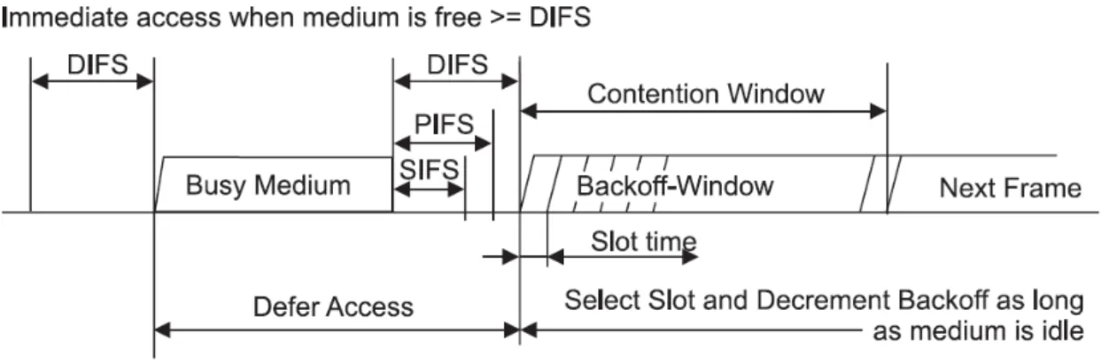
Figure 2.2 DCF timing chart.
When an STA wants to send a packet, it will detect channel condition firstly. If the sensed time duration is longer than DIFS, the packet will be sent immediately. Meanwhile, other STAs in the same IBSS will detect channel busy, defer their transmission and start exponential backoff process to avoid collision (see Fig. 2.1). During the backoff process, an STA will generate a random value, called backoff
timer, where
backoff timer = uniformly rand[0, contention window (CW)]*slot-time.
At the first transmission attempt, CW is set equal to a value CWmin, called minimum contention window. After each unsuccessful transmission, CW is doubled, until it reaches CWmax. The backoff timer, once generated, will be decremented until 0 continuously. The CW value is frozen when another station is transmitting and reactivated when the channel is sensed idle again for more than a DIFS. Once the backoff timer expires, the STA grabs the medium and transmits the packet. However, the backoff timer of different STAs may be the same. In such situation, the collided packets may be damaged and couldn’t be received successfully by the receiver. Hence, the sender won’t be able to receive a positive acknowledgement (ACK) from the
receiver and timeout mechanism is used to indicate the transmission failure. Every time a collision happened, the sender will double CW in order to avoid collision again and enter another exponential backoff process to retransmit the lost packet.
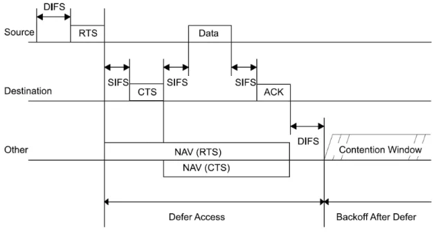
Hidden terminal problem occurs when a receiver hears both senders, but senders
can’t hear each other. In this situation, serious collisions may happen due to the failed detection of channel busy between senders. To overcome this phenomenon, RTS/CTS exchange procedure is introduced as an optional scheme. RTS/CTS scheme is similar to a channel probing mechanism. The sender transmits a short request-to-send (RTS) frame before each data frame transmission to make sure that no other node accessing channel in the same period. Upon receiving RTS from a sender, the receiver replies with a clear-to-send (CTS) frame if it is ready (see Fig. 2.2). Once the sender receives the CTS frame, it transmits a data frame. RTS and CTS packets carry the information of the length of the data packet to be transmitted. Such information is called network allocation vectors (NAV), which contains the information regarding the time duration in which the channel will remain busy. All other stations in the same BSS hearing an RTS frame or a CTS frame will update their NAV, and will not start transmissions until the updated NAV timer reaches zero. The RTS/CTS scheme not only solves the hidden terminal problem, but also significantly improves the performance of the basic DCF scheme when the data frame sizes are large. Contrarily, it may generate huge overhead when data frame sizes are small (e.g. a payload of VoIP is 160Bytes which needs about 116.4us to send, but the PHY header of each packet, including RTS, CTS, ACK and VoIP, is 196us in 11Mb 802.11b). Hence, RTS/CTS is introduced for only those packets with length larger than a certain threshold.
2.1.2 Point coordination function
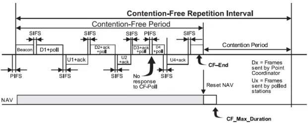
Point coordination function (PCF), an optional access mechanism, provides collision free and time bounded services. It is a centralized polling scheme, which uses the AP as a point coordinator (PC). When PCF mode is enabled, channel access time is divided into periodic intervals named beacon intervals. The beacon interval is consisting of two parts, a contention-free period (CFP) and a contention period (CP). On one hand, an STA uses DCF mechanism to grab the medium during CP. On the other hand, the PC maintains a list of registered stations and polls each of them according to the lists, during the CFP. When a station is being polled, it starts to transmit data frames after deferring SIFS (see Fig. 2.3). For the sake of utilization, data frames sent by, or in response to the polling by, the PC during the CFP shall use the appropriate data subtypes based upon the following usage rules:
Data+CF-Poll, Data+CF-Ack+CF-Poll, CF-Poll, and CF-Ack+CF-Poll shall only be sent by an AP.
Data, Data+CF-Ack, Null Function, and CF-Ack may be sent by an AP or by any CF-Pollable STA.
Figure 2.3 PCF timing chart.
for CF purposes, but shall only inspect the frame body if the frame is of subtype Data, Data+CF-Ack, Data+CF-Poll, or Data+CF-Ack+CF-Poll.
The time period for a PC to generate beacon frames is called target beacon transmission time (TBTT). Usually, PCF uses a round-robin scheduler to poll each station sequentially in the order of the polling list, but priority-based polling mechanisms can also be used if different QoS levels are requested by different stations.
2.2 Introduction of IEEE 802.11e
The article [4] shows several main challenges to provision QoS in WLAN. The first challenge is the network conditions such as channel condition and network load, always change over time. Second, the application profiles such as jitter, delay and throughput may vary significantly. Moreover, it is much harder to handle the application which used variable bit rate (VBR). The third challenge is managing the link layer resource, so called admission control.
PCF DCF EDCA HCCA 802.11b @2.4G 802.11a @5.4G 802.11g @2.4G MAC PHY 802.11e
Figure 2.4 IEEE 802.11 protocol layer.
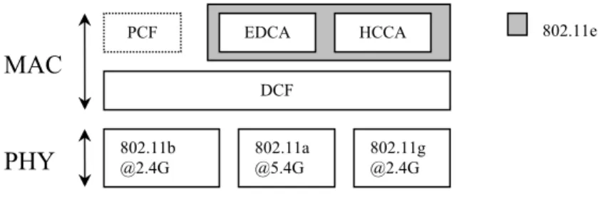
In order to overcome those problems, 802.11e is introduced to strengthen the QoS provisioning ability in WLAN. The relationship between the original 802.11 and 802.11e is shown in Fig. 2.4. 802.11e proposed a new MAC mechanism, hybrid
coordination function (HCF), which is composed of enhanced distributed channel access (EDCA), a contention-based mechanism; and HCF controlled channel access
(HCCA), a poll-based mechanism. Despite of HCF, 802.11e defines direct link protocol (DLP) which is used for transmission between STAs without passing through AP. ACK policies such as block-ACK policy used for best effort traffic and non-ACK policy used for real-time traffic, are also considered in 802.11e standard.
2.2.1 Enhanced distributed channel access
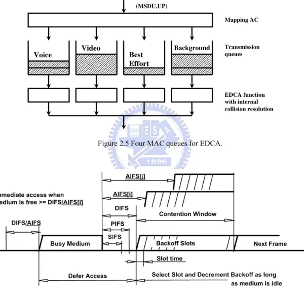
We can figure out that EDCA is an enhanced version of DCF. In EDCA, packet traffics are classified into four different FIFO queues (see Fig. 2.5), namely, access
categories (AC). Voice, video, best effort, and background traffics are mapping into
these four ACs. Before entering the MAC layer, each data packet received from higher layers is assigned a specific user priority value. How to tag such a priority value for each packet is an implementation issue. Every AC behaves as a single DCF contending entity and each entity has a parameter set, including arbitration interframe
space (AIFS), minimum contention window size (CWmin), maximum contention
window size (CWmax) and transmission opportunity (TXOP) duration, to differentiate
the transmission services. Those parameter sets are announced by the AP periodically via beacon frames. Despite of DIFS and PIFS defined in basic 802.11, EDCA introduces a new type of IFS, called arbitrary IFS (AIFS). Each AIFS is an IFS interval with arbitrary length and is determined by AIFS[AC] = SIFS + AIFSN[AC] ×slot time. The IFS relationship and related issue can be seen in Fig. 2.6.
After waiting for an idle time interval of AIFS[AC], each AC has to wait for a random backoff time. The purpose of using different contention parameters for different queues is to give high-priority traffic larger chance to access the medium earlier than those low-priority traffic. A potential problem is that the backoff times of different ACs overlap and it reduces the effect of service differentiation. Furthermore,
in EDCA, backoff timers of different ACs in one STA are random values and may reach zero at the same time, thus causing internal collisions. In order to avoid those internal collisions, EDCA introduces a virtual collision layer inside every STA to allow only the highest priority AC to transmit a packet. As a result, EDCA aims to support prioritized QoS for multimedia applications.
(MSDU,UP) Mapping AC Transmission queues EDCA function with internal collision resolution
Voice Video Best
Effort
Background
Figure 2.5 Four MAC queues for EDCA.
Figure 2.6 IFS relationship and related terms.
2.2.2 HCF controlled channel access
On the other hand, HCCA can be viewed as a more flexible version of PCF. An AP can start HCCA during both CFP and CP if it wishes, whereas PCF is only
allowed during CFP. During CP, an AP is allowed to invoke several contention-free bursts, called controlled access period (CAP), at anytime after detecting channel as being idle for a time interval of PIFS, which is shorter than DIFS and AIFSs. That gives the AP a highest priority to start HCCA at any instant during a CP than other contending STAs. The 802.11e beacon interval is cut into several service intervals (SI) and STAs are polled accordingly during each selected SI. The selected SI refers to the time duration between the start of successive TXOPs allocated to a STA, and it is the same for all stations. As soon as the SI is determined, the AP scheduler computes the different TXOP values allocated to different traffic streams for different STAs, which are TXOP1, TXOP2, etc.
Figure 2.7 Beacon interval is cut into several SI in HCCA.
Upon receiving QoS requests, the AP scheduler first determines whether SI is smaller than all requested SIs (RSI), and check whether SI is a sub-multiple of the 802.11e beacon interval duration. After that, AP will try to calculate the TXOP value
of those traffic in the STA by O
R MSDU R MSDU C TXOP PHY PHY Traffic Traffic Traffic ⎟⎟+ ⎠ ⎞ ⎜⎜ ⎝ ⎛ × =max , max ,
where O refers to the transmission overheads due to PHY/MAC layer frame headers, IFSs, ACKs and poll frames, MSDU stands for the length of MAC service data units (MSDUmax represents maximum one and MSDUTraffic represents average one), RPHY is
the average PHY transmission rate. ⎥ ⎥ ⎥ ⎤ ⎢ ⎢ ⎢ ⎡ ∗ = Traffic Traffic Traffic MSDU SI R
C , where CTraffic is the count
of packets to be sent in a single SI, RTraffic is data rate of this traffic and MSDUTraffic is
the packet length of each traffic. Finally, AP scheduler sums all the TXOP values of
different traffic streams in the same STA by TXOPSTA =
∑
TXOPTraffic and allocates the time interval for the STA. In this way, the AP scheduler is supposed to allocate the corresponding TXOP for transmitting all the arriving frames during the selected SI.Thus, the AP scheduler is expected to control the delays. However, this scheduling algorithm assumes that all types of traffic are constant bit rate (CBR), so the queue length increases linearly according to the constant application data rate. However, a lot of real-time applications, such as video conferencing, feature variable bit rate (VBR) characteristics. The simple HCCA scheduler may cause the average queue occupancy to increase and may possibly drop packets. Even if the mean transmission rate of the application is lower than the rate specified in QoS requirements, peaks of transmission rate may not be absorbed by TXOPs allocated according to the QoS
requirements.
A simple admission control algorithm is also suggested in a simple HCF scheduler: Beacon CAPLimit K i i K T T SI TXOP SI TXOP +
∑
≤ = + 1 1 , where TCAPLimit is the maximum duration
bound of HCCA, TBeacon represents the length of a beacon interval,
SI TXOPK 1+
refers to new additional TXOP and
∑
= K i i SI TXOP 1
means the current summation of TXOP. This algorithm insures that the impact of the new coming QoS-aware traffic to the currently running QoS-aware traffic is minimized to a certain level.
According to the aforementioned issues, HCCA solves three main problems of PCF:
(1) A direct link between peer stations is allowed in 802.11e, where stations can communicate each other without going through AP in HCCA period.
(2) An 802.11e STA is not allowed to transmit a packet if the frame transmission cannot be finished before the next beacon, which solves the beacon delay problem under PCF.
(3) A TXOPLimit is used to bound the transmission time of a polled station.
2.2.3 QoS flow setup and release procedure
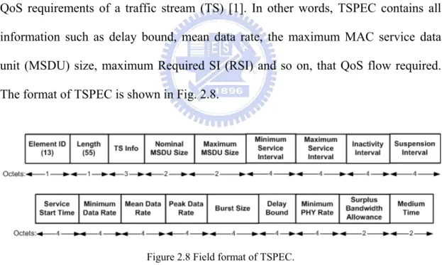
Traffic specification (TSPEC), the QoS characteristics of a data flow to and from a non-access point (non-AP) QoS station, describes the traffic characteristics and the QoS requirements of a traffic stream (TS) [1]. In other words, TSPEC contains all information such as delay bound, mean data rate, the maximum MAC service data unit (MSDU) size, maximum Required SI (RSI) and so on, that QoS flow required. The format of TSPEC is shown in Fig. 2.8.
Figure 2.8 Field format of TSPEC.
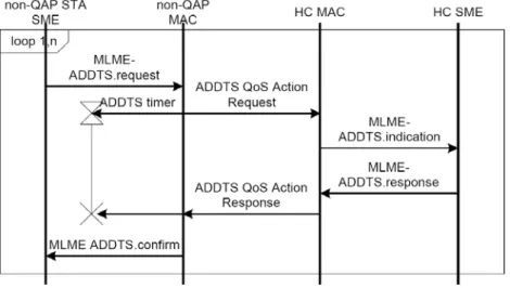
When a new QoS flow is created, STA uses ADDTS request with TSPEC to request an admission of the QoS flow (see Fig. 2.9). The AP replies with ADDTS response to the STA regarding whether QoS flow request is admitted into this IBSS. The format of ADDTS response is shown in Table 2.1. HCF will put this QoS flow into schedule list and poll it periodically by HCCA. After QoS flow transmission is
over, STA uses DELTS request to remove this QoS flow from HCF schedule list. More details can be seen in Chapter 11.4 of IEEE 802.11e specification.
Figure 2.9 Format of ADDTS response.
Table 2.1 Format of ADDTS response packet.
Order Information 1 Category 2 Action 3 Dialog Token 4 Status Code 5 TS Delay 6 TSPEC 7 ~ n TCLAS (optional)
n+1 TCLAS Processing (optional)
n+2 Schedule
2.3 Advantages and Disadvantages of WLAN MAC
Mechanisms
In the previous discussion, there two types of MAC transmission mechanism in WLAN. One is contention-based mechanism which includes DCF and EDCA. The other is poll-based mechanism which is used by PCF and HCCA.
The advantage of contention-based mechanism is suitable for dynamic change of traffic volume and network conditions. Furthermore, the complexity of EDCA is
lower than the poll-based medium access mechanism due to its distributed access characteristic. However, there are some problems using this kind of mechanism. One is the collision problem especially when multiple transmissions occur using the same channel at the same time or hidden nodes are existing. Random backoff is also another problem for provisioning QoS in WLAN, because the terms of randomness means probability instead of guarantee. The backoff time overhead is also another drawback.
There are several advantages when using poll-based mechanism. One is that hidden node problem no longer exists. The other is higher reliability in supporting QoS, because it is collision-free and centralized controlled. Channel utilization is much better than that in contention-based MAC mechanism too, because backoff time and collision overhead are reduced. Nevertheless, an AP needs to do static/dynamical scheduling work which is complex when using HCCA. The insufficient-poll and excessive-poll are also problems. Furthermore, scheduling in the situation that polling packets or polled packets sent during polling are lost should be considered.
2.4 Multimedia QoS Traffic Attributes and Channel
Capacity
We will discuss briefly QoS traffic attribute such as number of packets per second and required bandwidth here. The channel capacity for QoS traffics in 802.11b/a will also be addressed.
Generally speaking, VoIP traffic can be classified into two classes. One is constant bit rate (CBR) VoIP that generates packet every 5ms, 10ms, 20ms, etc. The other is variable bit rate (VBR) VoIP that only generates packet while talking. According to Table 2.2, we can see that the VoIP packet transmission frequency is very high and the payload is small compared to other type of packets. Moreover, in
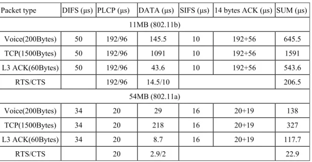
Table 2.3, we can see that the transmission overhead of VoIP is even larger than the original data. For example, in average we need about 580μs for MAC transmission overhead, including backoff duration, and 29μs for UDP and MAC header whereas only 116.5μs is required to transmit a G.711 VoIP payload over 11Mb 802.11b WLAN. Only 16% of transmission time is used for pure VoIP payload, thus even we use low rate VoIP with compressing codec, the total network utilization of VoIP couldn’t be increased too much. Since raw (none compressing) VoIP data with some errors is still acceptable and the difference can’t be distinguished by human ears, we suggest to use raw VoIP data to provide voice service over WLAN. The situation is the same on high PHY rate WLAN (802.11a/g), but compressed VoIP may be useful when STA’s average PHY rate is very low.
Table 2.2 VoIP Codec.
Codec bit rate[kbps] Payload [Bytes] frame duration [ms] Pkts[1/s]
G.711 64 160 20 50
G.723.1 5.3/6.4 20/24 30 33
GSM 13.2 33 20 50
G.729.1 8 - 32 20 - 80 20 50
Table 2.3 Packet transmission time.
Packet type DIFS (μs) PLCP (μs) DATA (μs) SIFS (μs) 14 bytes ACK (μs) SUM (μs) 11MB (802.11b) Voice(200Bytes) 50 192/96 145.5 10 192+56 645.5 TCP(1500Bytes) 50 192/96 1091 10 192+56 1591 L3 ACK(60Bytes) 50 192/96 43.6 10 192+56 543.6 RTS/CTS 192/96 14.5/10 206.5 54MB (802.11a) Voice(200Bytes) 34 20 29 16 20+19 138 TCP(1500Bytes) 34 20 218 16 20+19 327 L3 ACK(60Bytes) 34 20 8.7 16 20+19 117.7 RTS/CTS 20 2.9/2 22.9 17
Basically, a common number of video frames transmitted per second is 30fps with NTSC format. That means in a video stream, more than 30 packets will be generated per second periodically, because each frame may further consist of several packets. Generally speaking, the delay sensitivity for a video is less than that for a voice, therefore the priority for video traffic is less than the priority for voice traffic. There are lots of video applications with required bandwidth varying from 384Kbps for video conferencing, to several megabit for video on demand (VOD), and even higher for high-definition television (HDTV). Some of these video applications are CBR, but for the sake of video quality, some video applications use VBR. Moreover, most of video streaming over WLAN are downlink traffic, from wired to wireless. This feature may help us to design a more suitable MAC for QoS provisioning over WLAN.
Table 2.4 shows WLAN channel capacity for supporting each class of traffic [6]. VoIP that uses G.711 codec consists of two voice flows in the table. The bit rate of video is assumed 384kbps. Furthermore, TCP and video packets need RTS/CTS exchange process. Note that, this is an ideal case because it is assumed no collision and no packet loss in the table. In a real environment, due to lots of factors, the number of QoS flows will be much smaller than these ideal cases.
Table 2.4 Number of connection supported by different WLAN.
Traffic type 11b(11MB) DCF 11a(54MB) DCF 11b(11MB) PCF 11a(54MB) PCF
Voice 21 102 33 165
Bi-directional VoIP 10 51 16 82
Video 13 65 15 84
2.5 Related Works
2.5.1 DCF-based improvements
In our survey, most of those EDCA enhanced approaches [7] were focusing on adjusting EDCA parameters (e.g. CWmin, TXOP, persist factor (PF), AIFSN) especially in tuning CWmin. AEDCF [11] tries to change CWmin dynamically
according network condition. In [9], a table list of AIFSN and CW was constructed for the design of each AC in WLAN. In [13], an AP will measure channel condition and reconfigure the parameters of EDCA in each STA automatically.
Several adaptive schemes were proposed to change the procedure of random backoff during contention. Authors of [8] suggest a way that adapts CW to channel conditions and adjusts it depending on the network utilization and performance rather than generating a new CW randomly from a 2N number uniformly. Priority enforcement mechanism for request access was proposed in [15]. The basic idea
behind the method is that prioritized access to the wireless medium should be controlled through different backoff time periods. The method was published in [17] by using a Linear-increase Linear-decrease (LILD) model to adjust the Sliding Contention Window (SCW) range.
Further, two candidate methods of reinforcing EDCA are proposed in [14]. One is Backoff-interval based Service Discipline (BIWF-SP) which separates transmission
time of high-priority traffic from low-priority traffic by AIFSN differentiation. Briefly, high-priority packets will be sent strictly earlier than low-priority packets in the same IBSS. The other method is IFS-based Service Discipline (IDFQ-SP) which provides
strict priority service for each AC. Packets belonging to an AC, which randomly
generates AIFS values from a real number interval, are sent after AIFS without random backoff procedure.
The paper [19] suggests that an AP adaptively operates in EDCA or PCF mode based on the queue length of VoIP frames at the AP. If there are lots of packets buffered in the AP, it will work in PCF mode. Downlink VoIP frames access the channel without contention in the PCF access mode. On the other hand, if few VoIP packets were in AP, it will work in EDCA mode which is same as all STAs.
2.5.2 PCF-based enhancements
On the other hand, there are fewer researches of augment methods for HCCA than EDCA. Original HCCA recommended in 802.11e can handle CBR traffic well. However, treating VBR traffic is the main problem for HCCA. Some improvements are collected in [4] and [7]. Fair Hybrid Coordination Function (FHCF) [4] scheme tries to address dynamic variability in traffic flows by adjusting the TXOP of each flow using queue length estimations. Besides, SETT-EDD scheme uses the delay bounded earliest due date (Delay-EDD) scheduling algorithm instead of the default one in 802.11e. Furthermore, the SETT-EDD scheduler takes into account the impact of burst errors and link adaptation. Additionally, the paper [10] proposes a novel scheme that an AP uses clear-to-send packet (CTS) to create a small contention-free period for CBR VoIP traffic temporally. It is great that there is no modification requirement for STAs using the original IEEE 802.11. For further details, the article [20] collects almost all poll-based MAC mechanisms explicitly. Most of protocols in the article are regarding QoS packets scheduling algorithm.
Obviously, admission control is essential to provide QoS over WLAN. The authors of the article [18] survey a lot of approaches to do admission control over WLAN. Those suggested methods can be categorized into two types, which are measurement-based and model-based. The former was made based on continuously measuring network condition such as throughput and delay. On the other hand, the latter was trying to construct a certain performance metric to evaluate the status of the network. However, because of the variation of network and lots of interference factors, the researches of admission control still have long way to go.
Chapter 3 Proposed Approach
Firstly, for demonstrating the motivation of our proposed scheme, we investigate the phenomenon for QoS provisioning in an infrastructure wireless network.
(1) In some infrastructure WLAN environment, downlink traffic and uplink traffic are not balanced, because downlink traffic from AP to STA is much heavier than the uplink traffic from a single STA to AP. However, the transmission opportunity of a certain type AC in AP is same as that in an STA, thus all downlink flows share the bandwidth with those uplink flows from all STAs. It may result in that AP becomes the traffic bottleneck, so downlink traffic sent from AP may become a critical point of QoS provisioning over WLAN.
(2) Without separating real-time traffic from best effort traffic, we can’t ensure the bound of both delay and jitter of real-time traffic. In current approaches, polling mechanisms are used to do the work.
(3) Admission control is absolutely necessary for QoS provisioning. The simplest method is centralized admission control that is managed by AP.
Based on the observation above, we propose a scheme for providing QoS in WLAN environment. The scheme can be decomposed into three parts which consist of an AP management function on top of MAC layer and two EDCA parameter configurations to mitigate the jitter and delay of QoS-aware traffic. We also walkthrough our scheme by presenting an example, compare the scheme with EDCA and HCCA, demonstrate some assistance approaches and address related works. Finally, we address the well known hidden node problem, and present our approaches to accommodate the issue.
3.1 Main Scheme
The key idea of our main scheme is that an AP plays both the roles of a manager of global transmission parameters (i.e. AIFSN and CW) and an admission controller. The parameters management is based on the number of QoS ACs which is admitted to
transmit real-time packets in certain IBSS and the admission control is based on the requests of newly coming QoS flows. For simplification purpose in this thesis, a QoS AC stands for a QoS-aware AC queue and active DCF with its transmission parameter set. An AP is allowed to dynamically adjust the EDCA parameter values for certain ACs in either an STA or an AP, hence two ACs of the same type (e.g. voice AC) in different STAs may have different parameter values in our scheme, whereas those ACs will own the same parameter values in original EDCA (see Table 3.1). An AP either broadcasts or unicasts the necessary information to every STA, which can only react passively and follows the parameters assigned by the associated AP.
Table 3.1 Default values of parameters in 802.11e EDCA.
TXOP limit
AC CWmin CWmax AIFSN
For PHYs defined in Clause 15 and
Clause 18
For PHYs defined in Clause 17 and
Clause 19
Other PHYs
AC_BK aCWmin aCWmax 7 0 0 0
AC_BE aCWmin aCWmax 3 0 0 0
AC_VI (aCWmin +1)/2-1 aCWmin 2 6.016 ms 3.008 ms 0
AC_VO (aCWmin +1)/4-1 (aCWmin +1)/2-1 2 3.264 ms 1.504 ms 0
Furthermore, for the sake of handling variation in different network environments, AP may switch between two parameter configuration policies according the number of QoS ACs. The AP state transition diagram of configuration policy is shown in Fig. 3.1, whereas N means the number of QoS ACs contained in
AP and in all STAs, and θ means the threshold for state transition. The value of θ can be adjusted by administrators. Contention Window partition Unique AIFSN Assignment DCF/ EDCA N > 0 N > θ N = 0 N = 0 N ≤ θ N > 0
Figure 3.1 State transition diagram of AP.
There are three states in the state transition diagram, DCF, unique AIFS assignment (UAA) and contention window partitioning (CWP). If no QoS AC exists, the state is kept in DCF, and AP with all its associated STAs will use DCF or EDCA to transmit best effort traffic. Once a new QoS-aware flow appears, the state shifts to the UAA state and AP will assign a unique AIFSN for the QoS AC to handle the newly coming QoS-aware flow as well as re-adjust and broadcast a global AIFSN[BE AC] value via beacon. More details of UAA are described in Section 3.2.1. Next, if the number of QoS ACs exceeds a predefined threshold θ, AP will enter CWP state in which all QoS ACs of the same type (e.g. uplink voice AC) will share the same AIFSN and CW. More details of CWP are addressed in Section 3.2.2. Finally, when all QoS-aware flows are terminated, it returns to DCF state. In order to maximize the utilization, an advanced method that optimizes AIFSN usage is shown in Section 3.4.2. Noted that AP is the only one which keeps those state information and all STAs can only react passively and follow the parameters assigned by their associated AP.
An AP should keep global AIFSN[BE AC] as small as possible for the sake of higher channel utilization and better QoS of best effort traffic. We suggest that if there is no QoS-aware flow existing in an IBSS, the default value of AIFSN[BE AC] is globally set to 2, this is same as legacy DCF. Once a QoS-aware flow terminated or timeout, AP should check and decrease AIFSN[BE AC] if possible. Best effort packets can defer shorter time whenever it is possible due to the flexible AIFSN[BE AC] mechanism.
By default, the transmission time of downlink voice and video traffic sent by AP are separated from all uplink traffic and downlink best effort traffic in order to ensuring the QoS of audio and video downlink traffic. Hence, both voice and the video ACs of AP are always configured as UAA so that each QoS AC in AP has its unique AIFSN. In addition, an AP needs to keep two different states for uplink voice and uplink video. In other words, the state of uplink voice and uplink video may be different and AP should avoid the overlapping of transmission time of these two types of AC by AIFSN differentiation. For example, in 54Mbps 802.11a/g WLAN, if we have lots of VoIP calls and several video flows, we can treat uplink voice traffic with CWP and uplink video traffic with UAA. In such case, AIFSN of voice AC and video AC in AP is 2 and 9 relatively. AIFSN and CW of uplink voice AC is 3 and 6 relatively. AIFSN of uplink video AC can range from 11 to 15. Finally, AIFSN of best effort AC is 16.
Despite of parameters management, AP is also responsible for admission control for all STA requests. When a new time-bounded flow is initiated, STA uses ADDTS handshaking procedure defined in IEEE 802.11e standard to request transmission of QoS traffic. After the AP admitted this new flow and reconfigured the EDCA parameters of corresponding AC by the aforementioned method, STA is allowed to send QoS-aware packet via the AC. Most of the handshaking processes are same as
the original method mentioned in Section 2.3.2, except two parts. One is that we allocate a new field, named unique AIFSN for a new QoS AC, in ADDTS response packet sent from an AP. The other is that when a QoS-aware flow transmission is terminated or timeout, the STA uses DELTS to release the flow transmission and then AP reconfigures parameters of corresponding ACs. The flow chart for handling this procedure by the AP is shown in Fig. 3.2. The details of admission control will be addressed in Section 3.4.3. Start Bandwidth Available? N ≧ θ DCF Æ UAA UAA Æ CWP Reject
Response with AIFSN
Response
No Yes
Adjust AIFSN[BE AC] and broadcast it New QoS AC Response OK No Yes No Yes
Reset AINFS[BE AC] and reuse AIFSN
N = 0 Yes AP state switchs to DCF or EDCA N = N+1 N = N - 1 N = 1 No Yes Add/drop New request Flow terminated No
Finally, in terms of realizing the scheme, we need to implement an additional decision mechanism on AP management layer based on the state transition diagram and decision flow chart. Next, both AP and STA need to recognize an optional field that contains unique AIFSN information in ADDTS response packet. The increased complexity is very little and the computation overhead is also ignorable because the recalculation only occurs when a new flow comes in or an existing flow terminates. Importantly, the AP management layer is on top of the MAC layer, therefore the decision algorithm can be easily changed and redesigned according to the network condition and system requirement.
3.2 Two EDCA Configurations
We have already presented the basic idea of the main scheme and how an AP decides and performs state transition in Section 3.1. Here we introduce two EDCA parameter configurations for AP and STAs to achieve better QoS comparing with the original EDCA. These two configurations are suitable for various WLAN environments and can be adjusted and controlled by AP dynamically.
An InteServ-based configuration, called unique AIFSN assignment (UAA), is designed for WLAN environments with a practical number of active QoS ACs (e.g. no more than 8), no matter how many STAs or QoS-aware flows exist. In our approach, the AP assigns a unique AIFSN to an active QoS AC in STA after a
successful QoS handshaking. AP will make sure that each AIFSN[QoS AC] is smaller than AIFSN[BE AC] strictly and reconfigure the global AIFSN[BE AC] via beacon if necessary. Importantly, the admitted QoS AC sends packets directly without backoff procedure when the channel idle time is larger than AIFS. Since each AIFS of a QoS AC is unique and is smaller than AIFSN[BE AC] strictly, packets sent by QoS AC are
collision-free and can be transmitted as soon as possible. Hence, this approach not only reduces the overhead of collision but also decreases the MAC delay of time-sensitive packets. As a consequence, the QoS of real-time flows can be improved significantly.
In a high speed wireless LAN (c.f. IEEE 802.11a/g/n), we should be able to accommodate more number of QoS ACs. However, if we apply UAA for each uplink QoS AC, the deferral overhead and delay of best effort packets may be large due to large AIFS duration. Moreover, the influence of collision is also mitigated and may be ignored due to high transmission rate. Hence, a DiffServ-based configuration, called contention window partitioning (CWP), which can support more QoS ACs than UAA. This mechanism is similar to the original EDCA in which ACs will be classified into several groups based on their transmission priorities, except that we enlarge AIFSN by CWmax[higher priority AC] + AIFSN[higher priority AC] < AIFSN[lower priority
AC]. Through this method, we can guarantee that any higher priority AC always transmits before any lower priority AC. This mechanism increases the number of QoS ACs that can be supported, but it may generate a little jitter fluctuation due to possible collision.
Briefly, there are three features between those two configurations. The first is to
spilt QoS-aware traffic from best effort traffic and to subdivide QoS AC into two groups, uplink and downlink, by AIFSN differentiation. The second is, high priority AC can be guaranteed to acquire the transmission opportunity in both configurations,
whereas EDCA only supports that higher priority AC has better chance to grab wireless medium than lower priority AC. And the last issue is, the downlink QoS ACs have higher priority than uplink QoS ACs. There are three reasons for the last issus.
First, downlink packets may have traveled through a long way and experienced a long delay, therefore AP should forward them as soon as it can to avoid the possible drop
due to overflow in AP buffer. Second, downlink traffic from AP is much heavier than uplink traffic from a single STA, thus the average waiting time will decrease if we allow downlink packets to be sent earlier. Third, as mentioned before, downlink traffic may be a critical point of QoS over WLAN, and we could prevent an AP from being bandwidth bottleneck by sending downlink QoS-aware traffic with top priority.
The main differences between UAA and CWP are the effective number of QoS ACs and QoS reliability supported. When using UAA in an IBSS with large number of QoS ACs, the best effort traffic may suffer from both throughput degradation and large MAC delay. When applying CWP in a low data rate wireless network, the collision is serious and the jitter delay may be unacceptable. It is a tradeoff that can be decided by AP administrators and should be considered carefully. Fig 3.3 compares contention behaviors of four contention-based MAC mechanism, including DCF, EDCA, UAA and CWP.
DCF all EDCF QoS EDCF BE UAA QoS UAA BE CWP BE CWP QoS AIFS CW
Figure 3.3 Comparison of contention behavior of four MAC mechanisms.
3.2.1 Unique AIFSN assignment
For a contention-based MAC mechanism, collision and the behavior, that lower
priority packet cut in due to random backoff, usually cause uncertain jitter delay. To mitigate the jitter delay, unique AIFSN assignment (UAA) is proposed to provide better QoS by avoiding both collision and random backoff. UAA allows each QoS AC to have a unique AIFSN (see Fig 3.4) which is assigned by the AP and sends packets which may be belonging to different flows directly after deferring AIFS without backoff procedure. Noted that the AIFSN is given to QoS ACs instead of flows, thus no matter how many associated flows with a QoS AC, only one AIFSN needs to be assigned. Besides, for QoS guarantee’s sake, UAA insures that each AIFSN[QoS AC] < AIFSN[BE AC] strictly, therefore QoS-aware flows can always be sent before those best effort flows. We also suggest that AIFSN of downlink voice AC in AP is kept at 2 (see Fig. 3.4), because we want to give voice AC of AP the highest priority. Details of AIFSN assignment policy will be addressed in Section 3.4.1. A simple timing chart of contention between VoIP flow in AP and that in STA is shown in Fig. 3.5.
… ↓ EDCA UAA STAn or AP AC_VO
AIFSN=3 AIFSN=3AC_BE
STA1 AC_VO
AIFSN=3 AIFSN=10 AC_BE
STA6 AC_VI
AIFSN=9 AIFSN=10AC_BE
AP AC_VO
AIFSN=2AIFSN=8 AC_VI AIFSN=10AC_BE Figure 3.4 Comparing EDCA with UAA.
Figure 3.5 AC in an AP has higher priority than AC in an STA.
AIFS AIFS
AP
STA1
NAV AIFSN [STA VoIP] > AIFSN [AP VoIP]
Time ACK
VoIP F S DIFS
STA VoIP needs to defer AIFS which is longer than DIFS. Because of the NAV of AP VoIP, STA VoIP will wait after VoIP in AP transmits successfully.
S I ACK VoIP S I F S
At the ver P is 2, where AIFS is same as DIFS. Once a new QoS-aware flow such as VoIP comes in, the STA will issu
F
Transmission sequence
y beginning, AIFSN of each AC in STAs and in the A
e a QoS request firstly. If the QoS request is rejected by the AP, the QoS AC shouldn’t transmitted the flow and has to notify higher layer, but those admitted flows can still be transmit through the QoS AC. Oppositely, once the request is admitted by AP, the STA to which the new VoIP belongs will receive an AIFSN value for voice AC in QoS response packet sent from the associated AP (as described in Section 3.1.1), and be reminded again that AP needs to ensure AIFSN[QoS AC] < AIFSN[BE AC] and globally reconfigures AIFSN[BE AC] if necessary. Through the method, QoS-aware flows will be sent before best effort traffic without collision. After all queues of QoS ACs are empty, best effort ACs will try to compete with each other and transmit. The bandwidth of QoS-aware flows which use this method is guaranteed and the MAC delay is much shorter than that using original EDCA, this is due to collision-free transmission with high priority. UAA also ensures that each QoS AC will be guaranteed being able to transmit packets within a minimum SI if the bandwidth wasn’t exhausted by those higher priority flows, because best effort traffic won’t affect QoS-aware traffic.
VoIP STA (3)
Failed packet transmission
Figure 3.6 Transmission sequence of VoIP packets arriving at different STAs at the same time.
rom a global view point, UAA performs a priority guaranteed scheduling with
VoIP(3) VoIP(4) VoIP(7) BE Contention time Time VoIP STA (4)
VoIP STA (7)
Other traffic
sequence (at the MAC layer) Packet arriving
VoIP(3)
centr
Now, we want to discuss some problems, including fairness, starvation and maxi
alized priority assignment and automatic retransmission if any packet loss
happens. In Fig. 3.6, three VoIP packets arrive at their associated MAC at the same time where the number in the parenthesis is the AIFSN of the voice AC and it implies the priority (the smaller the number the higher the priority). Initially, VoIP(3) defers AIFS (AIFSN=3) then transmits, mean while VoIP(4) and VoIP(7) haven’t reached their AIFS. However, VoIP(3) packet wasn’t transmitted successfully due to interference and transmits again after deferring AIFS. Those packets will be sent sequentially without collision according to AIFSN. However, in worst cases, a lower priority VoIP packet may wait for a long time because a long packet such as video packet or best effort packet is transmitting and in the mean time some higher priority packets cut in (see Fig. 3.7). Fig. 3.8 demonstrates the timing chart that two VoIP packets and one best effort packet compete at the same time. In Fig. 3.8, we must indicate that the random backoff slots of best effort packet won’t make progress, if there is any QoS-aware packet to be sent, because AIFSN[QoS AC] < AIFSN[BE AC].
Time VoIP STA (4) Packet arriving sequence (at the MAC layer)
VoIP STA (7)
Figure 3.7 Higher priority packets will always be sent before lower priority packets.
mum/average MAC delay time. Obviously, UAA doesn’t emphasize fairness for
each QoS AC, instead it provides better QoS for higher priority AC. However,
VoIP(4) Transmission sequence
VoIP(7) BE Contention time Other traffics
Video STA (10)
because UAA denies best effort packets cut in, even the worst QoS for lowest priority AC using UAA is still better than the worst QoS using the original EDCA. Furthermore, simulation results show that the QoS difference between different priority ACs isn’t significant. If the fairness issue is essential, each QoS AC can take turns in using AIFSN periodically, just like frequency hopping system between beacon intervals, although it may be complex to implement.
Figure 3.8 Transmission sequence of two VoIP packets and one BE packet.
Best effort traffic starvation may occur if each time the STA grab the medium there
re packet needs to
AIFS
is a QoS-aware packet to send. Usually a QoS AC doesn’t send burst packets (e.g. VoIP usually generates one packet every 20ms), the bandwidth requirement is limited and QoS-aware traffic is separated from the best effort traffic, thus it is unlikely result in the starvation of best effort traffic in UAA. To prevent bandwidth from being exhausted by QoS-aware traffic, admission control is a must. Issues regarding admission control by AP are addressed in Section 3.4.3.
In WLAN applying UAA with heavy traffic, each QoS-awa
NAV Time STA1 STA2 VoIP S I F S ACK AIFS
VoIP VoIP ACK
S I F S AIFS
AIFS BE AIFS BE ACK
S I F S
STA3 BE AIFS
VoIP packet transmits directly after deferring AIFS
Lower priority VoIP packet has longer AIFSN and wait after higher priority packets transmitted
≈ BE Contention Window (varies between 31~1023) BE packet needs to defer AIFS and enter random backoff procedure, then it can be sent. Because AIFSN[BE] < AIFSN[VI], BE packet will always be sent after VoIP packet.
wait 50% duration of a currently transmitted packet in average and those QoS-aware packets with higher priorities before it can be transmitted. Hence, without considering channel error or interference, the maximum MAC delay of a QoS AC, ACQ will be
B T+1
∑
, where T is time of a QoS AC to complete the whole transmission time + packet transmitting time + ACK) per minimum SI, N represents the number of QoS ACs whose priorities are higher than ACN 2
(deferring
ly distr
Q, and B stands for the
transmission time of a maximum-length packet plus ACK transmission time. In some worst cases, the volume of QoS-aware traffic is very high and some higher priority packets are retransmitted due to interference. This causes low priority packets to wait for two or even three minimum SIs, because those packets have to wait until some of higher priority packets are retransmitted successfully, and during the waiting period some higher priority packets are generated and cut in again and again. Therefore, to avoid such cases the volume of QoS-aware traffic is suggested no greater than 80%, thus during each minimum SI we have at least 20% time that is originally used for best effort packet transmission to handle the retransmission of QoS-aware packets.
In general, the arrival time of QoS-aware packet in MAC will be random ibuted and the transmission time of QoS-aware packet won’t be overlapping with the transmission time of best effort packet in UAA, thus the number of contentions between QoS-aware packets would be small. Hence, the average MAC delay of a QoS-aware packet using UAA, DMAC, is obtained following:
∑
×∑
× + + = N i j MAC B P T D 1 (1 ε) ( ) = = i i j 1 1 2 2 (1)Here, B is the weighted average transmission time of a frame under curr
traffi
ent c condition, plus the transmission time of ACK, N stands for the maximum
time of QoS AC j to complete the whole transmission per minimum SI and
mean the longest waiting time for a QoS AC when i QoS ACs contend. The expect
waiting time of a QoS AC can be expressed by , where P
∑
= i j j T 1∑
∑
= = × N i i j j i T P 1 1 ) ( i defined inEquation (3) means the probability that i number of QoS ACs are contending at the
same time.
Note that the MAC queuing time may be ignored and most of time the QoS AC queue is empty in UAA, because each QoS-aware packet will be sent as soon as possible. If the number of packets in a QoS AC queue is more than the number of QoS-aware flows belonging to this AC, the channel must be fully occupied or severe interference happened.
For each packet, the deferring overhead can be viewed as the backoff, AIFS and collision. The backoff overhead of both UAA and original EDCA are the same,
because backoff time is shared by each packet no matter it is QoS-aware or best effort. More precisely, UAA reduces a certain level of collision, thus the average CW is smaller and backoff time is shorter. The average AIFS of each VoIP packet using UAA can be obtained by
M N AIFS N AIFS M k STAk AP + + ×
∑
=1 (2)N, M, AIFSAP, and AIFSSTAk indicate the number of downlink packets, the number
of uplink packets, AIFS of the QoS AC in AP, and the AIFS of the QoS AC in STA k.
Moreover, UAA provides a collision-free environment, thus the collision overhead is 0. Oppositely, we consider a best case of EDCA that QoS-aware packets only contend with best effort packets and the CW is always initiated to CWmin. Hence, the
minimum overhead of QoS-aware packet using EDCA is , where
R is the maximum number of retransmissions, P
∑
= × + R i i C P AIFS 1 ) ( Pi stands for the collision probability of
i times retransmission and C refers to the collision overhead. For a case that 8 VoIP
over 11Mbps 802.11b, where the slot time is 20μs, M and N are 8, P is 10% and C (1500 bytes) is 1091μs, we could find out that the average overhead of UAA, which is
95μs ( 8 8 ) 20 50 ( 50 8 1 + × + +
∑
= i i), is less than the minimum overhead of EDCA, which is about 170μs (
∑
). = × + 5 1 1091 ) 1 . 0 ( 50 i iThe extra IFS overhead regarding best effort packet using UAA can be viewed as
AIFS[BE AC]-DIFS. However UAA reduces the collisions between best effort
packets and QoS-aware packets, therefore the saved portion per second is
BE QoS N N O P× ×
, where NQoS means number of QoS-aware packets transmitted per
second, NBE means number of best effort packets sent per second, P presents the
probability of collision and O stands for the collision overhead. The average of extra deferring overhead for each best effort packet will be AIFS[BE AC]-DIFS-
BE QoS N N O P× ×
. For example in 11Mbps 802.11b with 6 VoIP flows and 6 TCP flows,
s Mbps bytes N N O P BE QoS 196μ 300 300 11 8 1500 18 . 0 = × × × = × ×
, AIFS[BE AC] is 9 × 20μs and
DIFS is 40μs, thus the extra IFS overhead will be -56μs. In other word, in this case
the overhead of our scheme is smaller than that of the original EDCA.
3.2.2 Contention window partitioning
However, UAA isn’t efficient for high speed WLAN such as 802.11a/g/n, due to the restriction of AIFSN (maximum 16 defined by IEEE 802.11e standard) and large overhead of best effort packet caused by long AIFS. Contention window partitioning (CWP), which is much similar to original EDCA, is proposed to support more QoS
ACs over high speed WLAN.
There are three main differences between EDCA and CWP. First, we enlarge AIFSN differentiation for each type of AC. If we enforce that CWmax[higher priority
AC] + AIFSN[higher priority AC] < AIFSN[lower priority AC], we can ensure that higher priority packets always transmit earlier than lower priority packets, and different types of AC will never collide. Second, downlink QoS-aware traffic sent from AP is separated from other traffic and always used UAA (see Fig. 3.9). Third, fixed CW instead of variable one, is used.
… … ↓ EDCA CWP STA1 AC_VO AIFSN=3 CWmin=7 CWmax=15 AC_BE AIFSN=3 STA3 or AP AC_VO AIFSN=2 CWmin=7 CWmax=15 AC_BE AIFSN=3 STA1 AC_VO AIFSN=3 CW=7 AC_BE AIFSN=12 STA3 AC_VO AIFSN=3 CW=7 AC_BE AIFSN=12 AP AC_VO AIFSN=2 CW=0 AC_VI AIFSN=11 CW=0 AC_BE AIFSN=12
Figure 3.9 Comparing EDCA with CWP.
An example is shown in Fig. 3.10 where two VoIP packets and one best effort packet wait for transmission. We can see that after STA1 has transmitted the packet, VoIP packet sent by STA3 with progress two slot whereas the best effort packet doesn’t progress. Here in order to mitigate the jitter caused by collision, it is recommended to use RTS/CTS before transmit long packet such as video frames.
Since we consider AP as a global parameters coordinator, therefore AP knows all the required control information, such as the number of QoS-aware flows, network load and channel status. AP can easily optimize those parameters, including CW and the setting for each AC. In addition, the packet loss rate caused by two competing
VoIP packets is R
P)
1
( , where R is the maximum number of retransmissions and P refers to collision probability. Even if we set a fixed CW value for voice AC, saying 7, the packet loss rate caused by two competing VoIP packets is )R
7 1 (
VoIP Contention Window (Fixed)
NAV Time STA1 STA2 ACK VoIP S I F S AIFS
VoIP VoIP ACK
S I F S AIFS AIFS AIFS BE AIFS BE BE ACK S I F S STA3
≈ BE Contention Window (varies between 31~1023)
AIFS
backoff slot 2
backoff slot 3 backoff slot progress from 3 to 1
backoff slot 1
Time backoff slot 1 backoff slot 1
Figure 3.10 Transmission sequence of two VoIP packets and one BE packet.
Maximum length packet ACK
QoS-aware packet arrives Another STA QoS-aware packet 2 arrives Two packets contends
Minimum service interval (SI)
M
Figure 3.11 Probability of packets contending during SI.
Moreover, we can separate SI into several segments with length
B SI
equally, thus the probability that packet arriving time of each QoS AC located on a certain segment is
SI B
, where B is the transmission time of maximum-length packet with ACK and SI represents the minimum SI (see Fig. 3.11). Therefore, the probability that
k QoS ACs are located on the same segment and contend with each other is then given by:
![Table 2.4 shows WLAN channel capacity for supporting each class of traffic [6]. VoIP that uses G.711 codec consists of two voice flows in the table](https://thumb-ap.123doks.com/thumbv2/9libinfo/8019297.160754/27.892.155.740.903.1052/table-shows-wlan-channel-capacity-supporting-traffic-consists.webp)
