Surface Topography and Alignment Effects in
UV-Modified Polyimide Films with Micron Size Patterns
Ru-Pin Pan1, Hua-Yu Chiu1, Yea-Feng Lin1, and J. Y. Huang2
1Department of Electrophysics, National Chiao Tung University, Hsinchu, Taiwan 300, R.O.C
2Institute of Electro-Optical Engineering, National Chiao Tung University, Hsinchu, Taiwan 300, R.O.C
(Received November 21, 2002)
The characteristics of UV-modified polyimide CBDA-BAPP films for liquid crystal (LC) alignment have been investigated. Linearly polarized ultra-violet laser light (¸ = 325 nm) was used to expose the film. The LC direction of this film tends to be oriented parallel to the surface and perpendicular to the polarization direction of the laser light. The uniformity of the LC direction stabilizes when the exposure time exceeds a certain length. From the atomic force microscope investigation, we find that the films have been dented at the places exposed to the laser light. When a mask with striped pattern was used during exposure, we observed grooves in the exposed regions. The grooved patterns agree well with the calculated diffraction patterns caused by the mask, however, the groove direction has no effect on the alignment of the LCs. In our experiments, we also achieved LC alignment patterns as small as 2 ¹m using UV exposure with a mask.
PACS. 61.30.Hn – Surface phenomena: alignment, anchoring. PACS. 68.37.Ps – Atomic force microscopy (AFM).
PACS. 82.50.Hp – Processes caused by visible and UV light.
I. Introduction
Surface alignment is one of the most important processes for liquid crystal (LC) devices [1]. Except for the cases where homeotropical alignment is created, a rubbing process is widely adopted to introduce an easy direction on the substrate plane. This process is reasonably reliable for achieving a uniformly oriented surface alignment; however, it is impossible to generate patterns with variable orientations. The fiber residues and static charges introduced by rubbing can also cause trouble for devices with fine patterns.
Although the grooving produced by rubbing can give an easy direction for a homogeneous surface [2], it is not the only mechanism for aligning LCs parallel to the rubbing direction [3]. It has been shown that the anisotropic dispersion force rather than the macro-surface groove effect is the major factor for the uniform alignment of LCs [4].
Photo-induced LC alignment has been studied for many years. As early as in 1991, Gibbons et al. had shown that the direction of the homogeneous alignment of LC molecules on specially designed optically controlled alignment polymers could be established and could even be altered
http://PSROC.phys.ntu.edu.tw/cjp 177 ° 2003 THE PHYSICAL SOCIETYc OF THE REPUBLIC OF CHINA
afterwards using polarized light [5]. Recently, ultra-violet (UV) sensitive polyimides (PI) have been intensively studied [6-9]. The alignment mechanisms includ photo-induced alignment of dye molecules [5], photo induced cross-linking reaction of polyimides [6], and photo-induced decomposition [7-9] of some groups when they absorb UV light. The mechanism, the process and the potential applications are all interesting subjects for our basic understanding of LCs and are useful for related industries.
In this work, we study the alignment properties of UV-irradiated polyimide surfaces used in devices with micron size patterns. The surface topography of these films has also been examined using an atomic force microscope (AFM).
In section II, we summarize our experimental methods, e.g., the material used, the processing steps for UV-irradiation, and the various methods employed for characterization or analysis. The experimental results, including the atomic force microscope observations of the surface and the optical observations of the LC alignment are given in section III. Then in the last section we discuss our results and their possible applications. In particular, we propose a model for the unique surface topography observed in this work. A conclusion is also presented.
II. Experimental method
We use a photosensitive PI, CBDA/BAPP [7], to coat the substrates. The chemical structure of CBDA/BAPP is shown in Fig. 1. The substrates are either silicon wafers or ITO (indium tin oxide) coated glasses. The substrates were cleaned with neutral detergent, trichloroethane, acetone and distilled water in an ultrasonic bath, and then dried at 60±C. A solution of 1.5 wt% poly-(amic acid) in N-methyl-2-pyrrolidinome was spin coated on the substrates at a rotation speed of 300 rpm for 5 seconds, and then at 3500 rpm for 20 seconds. The substrates were then cured at 80±C for 5 minutes and 250±C for 60 minutes.
In Ref. 7, the authors reported that this PI, after being irradiated by UV light from a Hg lamp, can induce an easy direction into the LC. The easy direction can be either parallel or perpendicular to the polarization of the linearly polarized ultra violet light (LPUV), depending on the wavelength of the light. When the PI was irradiated using LPUV light at a wavelength of 313 nm, they found that the easy direction was planar and perpendicular to the light polarization. In this work we employed LPUV at 325 nm from a He-Cd laser through a short pass filter for light irradiation. The intensity of the LPUV at the PI film substrates was 6 mW/mm2. The wavelength is very close to the wavelength used in Ref. 7, therefore we expected the easy direction to be the same.
We used masks with either a grating structure or a matrix of square openings with widths of 2 to 5 ¹m positioned right before the substrate, to make selected regions for exposeure to the LPUV. Exposure times were varied to study its effect on the alignment. Two kinds of substrates were used. Glass substrates were used to make LC cells on which the optical measurements were than carried out, while silicon substrates were used for an AFM surface topography study.
To examine the alignment quality, we used 6 ¹m thick planar LC (K15 from Merck) cells, made with nematic LC K15 (from Merck), sandwiched between one glass substrate having UV-exposed PI film and another glass substrate having rubbed PI film.
The topography of the irradiated PI films on the silicon substrates was examined by using a Commercial AFM (Topometrix TMX 2000 Discoverer scanning probe microscope) operating in contact mode. A standard Si tip with a force constant of 2N/m was used. The ambient temperature was 27±C and the humidity was kept at 50%.
III. Results
We used an optical microscope with crossed polarizers to examine the LC cells with the glass substrates. The exposed surface does give an easy direction perpendicular to the polarization of the LPUV. A longer exposure time gave sharper pattern contrasts. However, the alignment quality did not change much when the exposure time was greater than 45 minutes.
To make a quantitative study of the alignment quality, we made LC cells with the method mentioned above, but without any pattern. We used a He-Ne laser light to measure the transmit-tance through a pair of crossed polarizers with the LC cell in between. When the cell was rotated the transmittance followed the square of the sine relation but with a little shift up wards, i.e.:
T = A + B sin2(2µ);
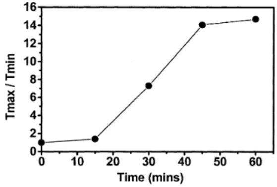
where µ is the angle between the LC molecules and the first polarizer, and A and B are constants. The contrast, Tmax=Tmin, was used as the index for the alignment quality. This is referred to as the alignment index in the remainder of the text. We found that the alignment index increases monotonically with the exposure time and reaches a value of about 14 for a 45 minute exposure. Beyond this point, it does not change much (See Fig. 2). The exposure energy density is 16 Joule/mm2 for a 45 minute exposure.
(a) (b)
(c) (d)
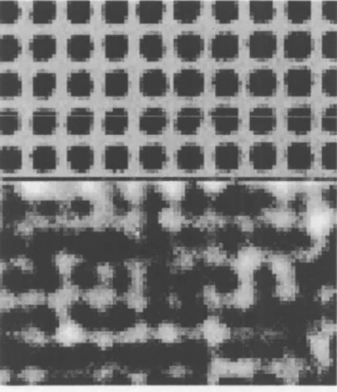
FIG. 3. Comparison of the topography of PI films after different treatments: (a) unexposed film, (b) exposed to UV for 60 minutes without a mask, (c) exposed to UV for 60 minutes with a mask having 2 ¹m-size square openings, (d) rubbed film without UV exposure.
The topography of the UV-exposed PI surface together with the unexposed surface and the rubbed surface are shown in Fig. 3. When we compare the non-exposed surface and the uniformly exposed surface [Fig. 3(a) and 3(b)], we found no obvious difference between them. The topography of the film surface exposed through the square-matrix-mask shows obvious dents at the exposed region [Fig. 3(c)]. Since the opening and the blocked part have the same width, it is clear that the size of dents is smaller than the transparent regions of the mask. The surface of the rubbed film is shown in Fig. 3(d); the dense grooves caused by rubbing can be seen clearly.
To study how the topography changes with exposure time, we used a mask with a single 3 ¹m slit. In Fig. 4, we show the topography of these UV-exposed film surfaces with different exposure times. For a 15 minute exposure [Fig. 4(a)], the topography of the film does not show distinctive features. This is consistent with the optical examination results shown in Fig. 2. The
(a) (b)
(c) (d)
FIG. 4. Groove formation during exposure to UV light. The topography of PI films exposed under UV light for (a) 15 minutes, (b) 30 minutes, (c) 45 minutes, and (d) 60 minutes. A mask with 3 ¹m slits was used.
alignment index is low for the film exposed for 15 minutes. After 30 minutes of exposure [Fig. 4(b)], a thin dentes line appeared. This is clear evidence that the exposure has begun to modify the PI film. Note that the dent area is narrower than that of the line slit (3 ¹m) in the mask.
When the exposure time was lengthened to 45 minutes or longer [Fig. 4(c) and (d)], the width of the dented area on the PI film was close to that of the slit. This is also consistent with the results of the optical microscopic measurements of an LC cell, from which we find that the alignment index approaches a saturated value for exposure times longer than 45 minutes (see Fig. 2). Although the alignment index is the same for the films exposed for 60 and 45 minutes, the grooves in the films exposed for 60 minutes are much more clear than those for 45 minutes.
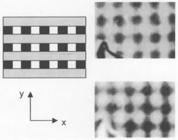
FIG. 5. Photographs taken under an optical microscope. The upper part shows a mask with a 2 ¹m square lattice opening. The lower part shows the LC cell with a glass substrate having PI film exposed to UV light using this mask. The exposure time was 60 minutes.
A lattice patterned LC cell is shown in Fig. 5. This cell is made with a substrate with PI film, which has been exposed to the LPUV with a mask having a matrix of square openings. The upper part of Fig. 5 shows a photograph of the mask taken with an optical microscope. The mask pattern consists of transparent 2 ¹m£ 2 ¹m regions with 2 ¹m opaque grids in between. The lower part of Fig. 5 shows a microscope picture of the LC cell between crossed polarizers. Alignment has clearly been achieved in the UV-exposed regions, as expected, although some cross talk did occur between the exposed regions. This was expected, because the pattern size was much smaller than the thickness of the cell (6 ¹m). Another LC cell with a similar lattice pattern, but with a 5 ¹m line-width was made with a different exposure method. This LC cell, shown in Fig. 6, was made with PI film doubly exposed under LPUV with a 5 ¹m striped mask. That is, the PI film was first exposed for 60 minutes with the light polarization parallel to the strip. At this step, 5 ¹m stripped regions of PI with and without aligning ability were formed alternately. Then the glass substrate was rotated by 90± and exposed to UV light again for another 60 minutes while the same mask was used again without rotation. After this second exposure, four different types of areas were formed: throse exposed twice, those exposed by either the first or second exposure only, and areas never exposed. The LC pattern alignment was very clear when the cell was examined under the microscope with crossed polarizers. It shows the darkest regions, the brightest regions and regions with intermediate brightness. The picture that we show here has a small defect, which was chosen on purpose to make certain that we are showing the same region of the cell when the polarizer direction is changed. This result is important; it suggests that various orientations and degrees of alignment can be tuned by varying the exposure time and by multi-exposures.
FIG. 6. LC cells using a glass substrate with double exposed PI film. The left figure shows the mask configurations and the exposed areas. The black strips show the area of first exposure and the gray strips show the area of second exposure. The right side figures show microscopic photographs of the LC cell between crossed and parallel polarizers, respectively. A defect in the cell is used to identify the identical cell regions in both photographs.
IV. Discussion and conclusions
In this work, we have demonstrated that LC cells with an aligned square lattice can be produced from polyimide film by a UV exposure technique. The alignment direction is determined by the polarization of the UV light. The alignment patterns can be controlled using a mask with designed opening patterns in front of the substrate. The aligned area can be as small as 2 ¹m£ 2 ¹m (Fig. 5). Furthermore, mixed alignment patterns can also be obtained with double exposures (Fig. 6).
Our AFM study shows that the thickness of the film decreses at the exposed area. When a mask with square openings was used, the dented area was much smaller than the openings [Fig. 3(b)]. When a mask with micron-size line openings was used, the film shows fine grooves (Fig. 4) parallel to the opening in the exposed region. We have compared the height profile with a calculated Fresnel diffraction intensity pattern, as shown in Fig. 7. Since the diffraction intensity pattern of the laser light from a line slit is similar to the thickness decreasing profile of the film, we conclude that the grooves formed because of the non-uniformity of the light intensity caused by diffraction. This phenomenon of thickness decreasing suggests that some material was released at the exposed region. The fact that the dents in the film surface have area smaller than the openings and do not have sharp edges (see Fig. 3(b)) can also be explained by light diffraction through the mask of square openings.
In spite of the grooved structure of the film surface, the LC alignment direction is determined by the light polarization rather than the surface structure. In the grating mask experiments, it was confirmed that the direction of the grooves had no effect on the LC alignment direction. From the
FIG. 7. (a) The calculated Fresnel diffraction pattern for a plane wave (wavelength = 325 nm) passing through a 3 ¹m slit on a screen 2.1 ¹m behind the slit. (b) The surface height variation of the UV exposed polyimide film along the cross line in Fig. 4(d).
polarized microscopic pictures of the LC cells, we can see that the size of the aligned area is close to that of the mask openings (Fig. 5 and 6), rather than the area of dented surface [Fig. 3(b)].
Although the grooves do not contribute to the LC alignment, they can have other potential applications. This phenomenon of groove production actually suggests that we can use a spatial intensity modulated UV light to make fine lines on polyimide film. These films can then serve as phase gratings, and the amplitude of the phase change of the gratings can be controlled by the writing light intensity and the time.
References
[ 1 ] T. Sugiyama et al., Jpn. J. Appl. Phys. 29, 2045, (1990). [ 2 ] D. W. Berreman, Phys. Rev. Lett. 28, 1683 (1972). [ 3 ] Y. M. Zhu et al., Appl. Phys. Lett. 65, 49 (1994). [ 4 ] D. S. Seo et al., Jpn. J. Appl. Phys. 34, 4876 (1995).
[ 5 ] W. M. Gibbons, P. J. Shannon, S. T. Sun, and B. J. Swetlin, Nature (London) 351, 49 (1991). [ 6 ] M. Schadt, H. Seiberle, and A. Schuster, Nature (London) 381, 212 (1996).
[ 7 ] H. Endo et al., Proceedings of the Active-Matrix Liquid Crystal Display 96, p. 341, 1996. [ 8 ] Y. Wang et al., J. Appl. Phys. 84, 181 (1998).