A Transputer-Based Adaptive Speed Controller
for AC Induction Motor Drives with
Load Torque Estimation
Ming-Fa Tsai, Student Member, IEEE and Ying-Yu Tzou, Member, IEEE
Abstract—In this paper, we design and implement an adaptive speed controller that can estimate load torque for ac induction motor drives employing a transputer-based parallel processing technique. The adaptive speed controller, which precedes the field-oriented control loop, consists of a two-degree-of-freedom controller and a feedforward load-torque compensator. The two-degree-of-freedom controller is designed by a pole-placement technique with polynomial manipulations. Its parameters are adjusted adaptively in terms of estimated model parameters. Estimating the model parameters entails a second-order least-squares estimator with constant trace to avoid estimator windup. The design of the feedforward compensator is based on an estimated load-torque model. Estimating the load torque entails a first-order least-squares estimator with variable forgetting factor and covariance resetting, the purposes of which are to detect any slow or sudden changes of torque disturbance, respectively. The resulting adaptive controller is implemented in parallel by IMS T800-20 transputers. Experimental results demonstrate the robustness of the proposed control method in contending with varying load and torque disturbance.
Index Terms—Adaptive control, induction motor, load torque estimation, transputers.
NOMENCLATURE
Stator resistance per phase. Rotor resistance per phase. Stator inductance per phase.
Rotor inductance per phase referred to stator. Mutual magnetizing inductance per phase. Number of poles.
Differential operator.
Synchronous rotating frame angular speed. Motor electrical angular speed.
Motor rotor angular speed. Slip angular speed.
-axis ( -axis) stator voltage. -axis ( -axis) stator current.
-axis ( -axis) stator current command. -axis ( -axis) rotor current.
Paper IPCSD 96–58, approved by the Industrial Drives Committee of the IEEE Industry Applications Society for presentation at the 1995 IEEE/IAS In-ternational Conference on Industrial Automation and Control, Taipei, Taiwan, R.O.C., May 22–27. Manuscript released for publication October 21, 1996. This work was supported by the National Science Council, Taipei, Taiwan, R.O.C., under Project NSC84-2213-E009-010.
The authors are with the Power Electronics and Motion Control Laboratory, Institute of Control Engineering, National Chiao Tung University, Hsinchu, 30050 Taiwan, R.O.C. (e-mail: [email protected]).
Publisher Item Identifier S 0093-9994(97)01543-0.
-axis ( -axis) stator voltage. -axis ( -axis) stator current.
-axis ( -axis) stator current command. -axis ( -axis) stator flux linkage. -axis ( -axis) rotor flux linkage. Motor developed torque.
External load torque. Motor rotor inertia. System total inertia. Motor viscous coefficient. System total viscous coefficient. Torque constant.
Back EMF voltage constant. Model mechanical time constant. Model electrical time constant. Motor rotor time constant.
I. INTRODUCTION
P
RESENT-DAY automation industry increasingly demands high-performance electrical servo drives, particularly of the type that guarantee asymptotic tracking and regulation, irrespective of changes in load or motor parameters or of load torque disturbances. Adaptive control methods that take torque disturbance suppression into account have been utilized to improve servo drive performance and help maintain invari-ant control behavior in a wide range of variable operating conditions [1]–[4].Basically, such speed control systems for ac servo drives come in two categories: a model reference adaptive system (MRAS) and a self-tuning regulator (STR). In a MRAS system, a control input drives the controlled plant, tracking the response produced by the reference model; research work on this aspect is not lacking [5]. On the other hand, the STR system explicitly estimates plant model parameters and, based on these, then redesigns the controller to control the invariant speed [6]–[8]. Although research to date into adaptive speed control for ac motor drives is not lacking, attention must be given to ascertain the effects of adaptive control schemes and of the compensation of load torque disturbance when the motor parameters change and load torque disturbance occurs, giving rise to improve the performance.
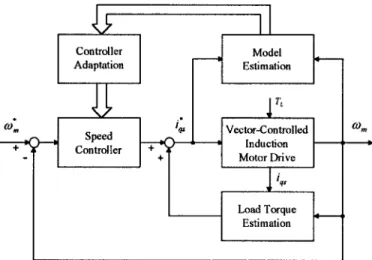
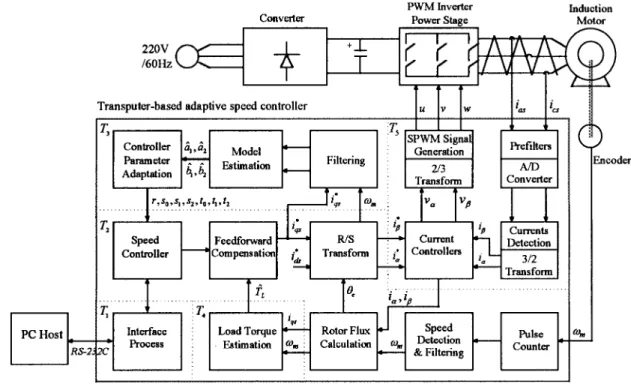
As illustrated in Fig. 1, the adaptive controller presented herein most closely relates to a self-tuning regulator which can additionally estimate external load torque for reducing the
Fig. 1. The functional block diagram of an adaptive controller with load torque estimation for an ac induction motor drive.
torque disturbance effect by feedforward compensation. Esti-mating load torque requires a first-order least-squares estimator [9], rather than the conventional observation technique by a load torque observer [10]. In this way, the model parameters and load torque estimations are separate and the self-tuning regulation and feedforward compensation are decoupled and, hence, can be independently designed. Compensating torque disturbance can enhance the robustness of the system. How-ever, applying the method to an ac induction motor drive for rapid response control has been somewhat restricted due mainly to the control algorithm, the complexity of which has proved a considerable obstacle in the way of microcontrollers and microprocessors. The advent of high-speed 32-b trans-puters, operating at a 20-MHz (or above) clock frequency [11], renders the complicated control algorithm amenable to implementation in parallel, resulting in a high sampling-rate operation.
This paper presents the design and implementation of a self-tuning adaptive speed controller that can additionally estimate and feedforward compensate load torque for ac induction motor drives, employing a transputer-based parallel processing technique. The system can rapidly compensate any output error caused either by variation of the motor parameters or by ex-ternal torque disturbances. Experimental results demonstrating the proposed controller’s effectiveness are presented.
II. DYNAMIC MODELING OF AVECTOR-CONTROLLED
AC INDUCTION MOTOR DRIVE
The dynamic properties of an induction motor as a con-trolled plant may be described by a set of nonlinear differential equations linking the stator and rotor currents and the voltages with the mechanical quantities, such as torque, speed, and angular position. The analysis and control of such a plant appears complicated because of the intricate coupling of all the control inputs, but the problem can be overcome by controlling the field-oriented quantities, which reduce the control of an ac induction motor to that of a separated excited dc motor [12].
In deriving the dynamic model of a field-oriented or vector-controlled induction motor drive, the voltage and
developed-torque equations for an ac induction motor of the squirrel cage type can be expressed in terms of the - axes components in a synchronous rotating frame as follows:
(1) (2) (3) (4) (5) where (6) (7) (8) (9) and (10) All symbols are listed in the Nomenclature at the beginning of this paper. Eliminating , and in (1)–(4) by employing (6)–(9), the voltage equations in terms of stator current and rotor flux linkage can be restated in matrix form as
(11)
where is the differential operator and
(12) The developed-torque equation in (5) becomes
(13) Ideal decoupling control between - and -axes can be achieved by aligning the rotor flux vector to the -axis and setting the rotor flux linkage to be a constant, which means
(14) constant (15) Employing (14) on the third and fourth row of (11) yields
(16) and
Further, the torque equation in (13) becomes
(18) Thus, with the condition of (15), which can be achieved by setting the command to be a constant when the motor is operating in its constant-torque region, the motor’s torque generation, with decoupling, can be controlled by the stator current .
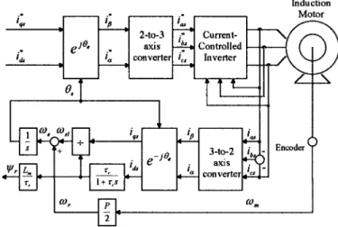
The vector control scheme, which employs a rotor flux model based on (16) and (17), is illustrated in Fig. 2. Note that the current-controlled PWM inverter has also been included in the system. To obtain the equivalent vector-controlled plant model for the adaptive controller design, the current control dynamics should be considered. Taking a traditional current-controlled sinusoidal PWM inverter drive, let be the equivalent current controller gain; then, the torque-producing current control action can be modeled as
(19) Incorporating (10), (12), (14), (15), and (17) into the second row of (11) yields
(20) The developed-torque equation and the rotor angular speed are related by
(21) Equations (18)–(21) consequently constitute the dynamic model of the vector-controlled ac induction motor drive represented by the block diagram in Fig. 3. The open-loop response of can be expressed from Fig. 3 as
(22) where and are as shown by (23) and (24), at the bottom of the page. In (23) and (24)
(25) (26) (27) where
steady-state gain;
mechanical time constant; electrical time constant.
Fig. 2. Vector control scheme of an ac induction motor drive.
Fig. 3. Equivalent model of the vector-controlled induction motor drive.
Since the load torque is an inaccessible input, the transfer function will be used as the plant model for the adaptive controller design. The magnitude of torque disturbance will be estimated by estimation theory and then eliminated by feedforward compensation.
III. ADAPTIVE SPEED CONTROL WITH LOAD TORQUE ESTIMATION
The adaptive controller for the ac induction motor drive consists of an on-line parameter estimator, a 2-degree-of-freedom controller adaptation, and an estimator-based load torque compensator. These are described as follows.
A. Parameter Estimation
For the parameter estimation, the pulse-transfer function of in the -domain can be derived through a zeroth-order hold device as
(28)
(23)
where are function of the motor parameters and can be obtained as
(29) (30) (31) (32) where is the sampling time. The linear difference equation of the process is
(33) To be able to estimate the parameters , and , the difference equation is expressed in a predictor form as
(34) where the regression vector is
(35) and is an estimated vector of the system parameters
(36) The estimation has mostly been done using the recursive least-squares method with exponential forgetting factor. How-ever, this method works well only if the process is properly excited all the time. This is not realistic for servo systems because there may be long time intervals without excitation from the reference input and, hence, a problem called estimator windup will occur [13]. To avoid the estimator windup, one version of the regularized constant-trace algorithm is adopted for the model parameter estimation. The estimator is given as [14] (37) (38) (39) (40) otherwise (41) where ; the variable introduces a dead zone in the estimator, and is a magnitude estimate of the noise. In this way, the trace of the covariance matrix is kept to be constant in each iteration to provide the adaptation capability for parameter change. Further, the dead zone prevents the estimator from drifting when the errors are small and when the system is not persistently excited. Typically, the estimator parameters are selected such that
and .
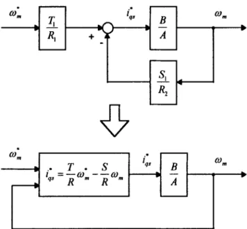
Fig. 4. The 2-degree-of-freedom structure of the pole-placement controller.
B. Controller Adaptation
The design of the speed controller is based on pole place-ment with polynomial manipulation technique for its simplicity and easy-to-use nature [14]. According to this method, the speed controller is considered to be a two-degree-of-freedom structure, as shown in Fig. 4. The controller has one output, the torque-producing current command, , and two inputs, the speed command, , and the motor speed, . The speed controller with these inputs and outputs can be represented by (42) where , and are polynomials in . The control law of (42) can be written as
(43) where
, and is monic, i.e., the coefficient of the highest power in is unity. Combing the speed controller (43) with the pulse-transfer function of the motor drive (28) yields the closed-loop pulse-transfer function as follows:
(44) To carry out the speed controller adaptation, the parameters of the controller polynomial are obtained by solving the following Diophantine equation:
(45) and
where is the desired closed-loop characteristic polynomial, is the canceled-out polynomial in (44), and the controller polynomials are expressed as
(47) (48) (49) One should note that the in (47) contains an integral factor which is required for zero steady-state error. Specifica-tion of the system can be expressed in terms of the desired closed-loop transfer function as
(50) where and do not have any common factors.
For ease of the design, the desired properties of the closed-loop system can be first specified in the -domain by requiring that the response to a command signal has the characteristic polynomial
where is the damping ratio and is the natural frequency. Then, the equivalent discrete-time polynomial with the sam-pling time can be derived and given by
(51) The roots of the cancellation polynomial can be assigned at , which is on the negative real axis with dynamic faster than the desired closed-loop response determined by
. Then, the discrete-time cancellation polynomial is (52) The controller parameters then can be obtained by solving the Diophantine equation (45) and (46). The control law derived from (42) becomes
(53)
C. Load Torque Estimation and Compensation
Similar to the model parameter estimation method described above, estimating load torque entails a recursive least-squares algorithm. As can be seen from Fig. 3, the transfer function from the torque-producing current to the motor speed output is a first-order system with the form
(54)
(a)
(b)
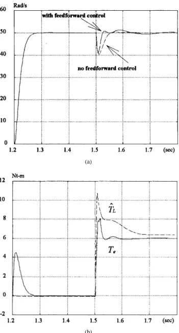
Fig. 5. Simulation results for a load torque of 6 N1m suddenly applied at 1.5 s. (a) Speed response with feedforward compensation (solid line) and without feedforward compensation (dash line). (b) Producing-torque response with feedforward compensation (solid line) and the estimated load-torque convergence behavior (dash line).
TABLE I
PARAMETERS OF THETESTEDINDUCTIONMOTOR.
The discrete-time equation with load torque disturbance can be obtained through a zeroth-order holder as follows:
(55) where and , in which
Fig. 6. Configuration of the transputer-based adaptive speed control system.
Fig. 7. Transputer topology for the parallel implementation.
is the sampling time. To estimate the load torque, we rewrite (55) into the same form as (34), but here the regression vector and estimated parameter vector are, respectively, as follows:
(56) and
(57) Then, the load torque can be estimated as
(58) In order to immediately detect when a slow or sudden change of torque disturbance has occurred and take appropriate
action, we adopt the least-squares algorithm with variable forgetting factor. This algorithm is
(59)
(a)
(b)
Fig. 8. Experimental results of the adaptive speed control response. (a) Motor shaft speed. (b) Model parameters’ convergence behavior.
where the forgetting factor is
(61) In (61), is the prediction error and is a tuning parameter. Thus, if a torque disturbance occurs, the prediction error square increases; this reduces temporarily but increases the covariance matrix quickly so that rapid adaptation can occur. After adaptation, the prediction error square decreases and returns a value near one. The prediction error square can be further monitored to detect a sudden change of load torque. If the prediction error square excesses a preset threshold value, we can reset the covariance matrix for quick adaptation to get the true parameter of the load torque estimation.
For getting fast convergence of the estimated parameters, the sampling rate can be set to be two or more times of that in the speed control loop. The estimated load torque then is
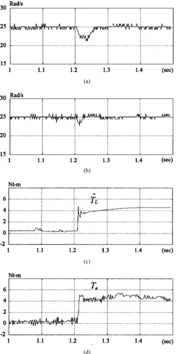
(a)
(b)
(c)
Fig. 9. Comparison of the performance for the system inertia suddenly increased just prior to 1.2 s. (a) Without adaptation. (b) With adaptation. (c) Model parameters’ convergence behavior with adaptation.
directly added to output of the 2-degree-of-freedom controller for feedforward compensation.
Before the implementation of the proposed adaptive con-troller, the computer simulation is made to test the effec-tiveness of the control scheme. The motor parameters used are listed in Table I. The selected parameters of the model estimator (37)–(41) are
, and . The selected parameter of (61) in torque estimator is and the threshold value of prediction error is 0.6. The design specifications are
Rad/s and . Fig. 5(a) shows the comparison between the performance with and without feedforward load-torque compensation when a load torque of 6 N m is suddenly applied at the time of 1.5 s. As can be seen, the speed response with reduced deviation is achieved by using the feedforward compensation. The corresponding load-torque estimation con-vergence behavior and the motor developed-torque response are shown in Fig. 5(b).
(a)
(b)
(c)
(d)
Fig. 10. Comparison of the performance for the load torque suddenly increased. (a) Without feedforward compensation. (b) With feedforward compensation. (c) The estimated load torque. (d) The motor developed torque with feedforward compensation.
IV. TRANSPUTER IMPLEMENTATION AND EXPERIMENTAL RESULTS
Fig. 6 illustrates the configuration of the transputer-based adaptive speed control system of an ac induction motor drive. The induction motor employed in this paper is a NIKKI product NA20-40F, the parameters of which are shown in Table I. The load torque change is implemented by employing a loaded dc generator that is directly coupled to the rotor shaft of the induction motor. A close contact on the output terminals of the dc generator, which is in series with a current-limiting resistor for protection, can produce a constant torque proportional to the motor speed on the counter rotary direction of the motor. The system inertia change is implemented by employing a rigid cylinder load that is connected to the
TABLE II
COMPUTATIONTIME OF THEPARTITIONEDCONTROLTASKS.
induction motor shaft through an electromagnetic clutch. The load can be immediately attached or detached to the motor by controlling a dc power supply, which is applied to the clutch. The moment inertia of the rigid cylinder load is 0.0064 kg m , which is about 2.2 times that of the motor rotor. The position and speed of the motor shaft are detected by a rotary encoder with 2000 pulse/revolution. The stator currents are measured by using Hall-effect sensors and then converted to digital values by a multiplexed 12-b analog-to-digital converter (AD1678). The induction motor is driven by a current-controlled POWER-MOSFET-based voltage source inverter with the current limit of 18 A.
Instead of using INMOS-provided transputer boards, two transputer-based modules, one called I/O module (IOM) and the other called parallel computing module (PCM), were developed to build the system [15]. The transputer is not only a powerful microcomputer (10 MIPS and 1.5 MFLOPS for IMS T800-20), but also acts as a parallel processing element. Parallelism is supported by the transputer intrinsic hardware and software capabilities. Each transputer has four independent serial links which provide point-to-point connections between transputers with communication rate up to 20 Mb/s. In order to reduce the computation delay, we employed five trans-puters for the implementation. Transputer performs the speed detection and filtering, the speed compensation, and the vector control which contains the rotor flux calculation and the rotating-to-stationary coordinate transformation. performs the model estimation and the controller adaptation. The estimation of the external load torque is assigned to . performs the current detection, the current regulation, and the sinusoidal PWM signal generation. acts as the system supervisor and provides the user interface and data storage. Through an RS-232C communication interface, the software and data can be transmitted between the transputer-based adaptive control system and the host computer. The interprocess links of transputers are two-wire connections by which a grid structure is obtained, as shown in Fig. 7. The parallel structure planning is configured by the software in the high-level programming language, Occam [16].
The selection of the sampling time for each process invari-antly relates to the control dynamics and the computation time needed for the task execution. Table II shows the task com-putation time of the partitioned control algorithm. To achieve fast convergence of the load torque estimation, transputer performs the software routine every 200 s. To get fast current loop response, the sampling time in is 100 s. The software routine in and are executed every one ms.
Based on the constructed system and the selected param-eters of the adaptive control scheme described above, the experimental results are shown in Figs. 8–10. Fig. 8 gives the dynamic motor speed response to a square wave command with period of 800 ms and magnitude from 50 to 50 rad/s to provide the necessary excitation for model estimation. One can see that on the first excitation the four param-eters are convergent from the initial guess (0, 0, 1, 1) to ( 0.50, 0.47, 0.16, 0.68) which makes that the speed output error is zero. On the next excitation, the four parameters are convergent to the true parameters ( 0.47, 0.52, 0.02, 0.47) and, hence, the speed output reaches the desired response. Fig. 9 presents a comparison between the performance with and without adaptation, if the load is suddenly applied just prior to the time of 1.2 s, at which the reference input has a step change, and the parameters transient behavior. The speed response without adaptation, as shown in Fig. 9(a), is kept well before the load is attached. But while the load is attached, overshoots occur when the reference input has step changes. On the contrary, as shown in the Fig. 9(b), for the performance with adaptation, only an overshoot occurs at the first excitation (1.2 s) while the load is attached because of the parameters transient behavior from ( 0.47, 0.52, 0.02, 0.47) to ( 0.49, 0.49, 0.17, 0.36). No more overshoots occur at the subsequent excitations while the load remains attached and, hence, the performance is improved. Fig. 10 gives a comparison between the performance with and without feed-forward compensation for a sudden increase of load torque from 0.5 to 4.5 N m, indicating that the performance with feedforward compensation is more robust than that without feedforward compensation in contending with the load torque disturbance.
V. CONCLUSION
This paper has developed a transputer-based adaptive speed controller with the addition of estimator-based load torque compensation for high-performance control of an ac induction motor. For reducing the computation delay and enhancing the overall system performance, we employed four transputers to execute the control algorithm in parallell, which contains the model parameter estimation, the controller adaptation, the speed compensation, the vector control, the current control and sinusoidal PWM, and the load torque estimation, and one transputer for the user interface processing. Estimating the load torque entails a recursive least-squares method rather than the conventional load-torque observation technique. Experimental results demonstrate the robustness of the proposed adaptive speed control method in contending with varying load and torque disturbance.
REFERENCES
[1] K. Ohishi, K. Ohnishi, and K. Miyachi, “Adaptive DC servo drive control taking force disturbance suppression into account,” IEEE Trans.
Ind. Applicat., vol. 24, pp. 171–176, Jan./Feb. 1988.
[2] A. Chandra, L. Dessaint, M. Saad, and K. Al-Haddad, “Implementation of self-tuning algorithms for reference tracking of a DC drive using a DSP chip,” IEEE Trans. Ind. Electron., vol. 41, pp. 104–109, Feb. 1994. [3] K. H. Gurubasavaraj, “Implementation of a self-tuning controller using digital signal processor chips,” IEEE Contr. Syst. Mag., pp. 38–42, June 1989.
[4] E. Bassi, F. Benzi, and R. Scattolini, “Design of a digital adaptive controller for electrical drives in industrial applications,” IEEE Trans.
Ind. Electron., vol. 39, pp. 120–127, Apr. 1992.
[5] C. M. Liaw, C. T. Pan, and Y. C. Chen, “Design and implementation of an adaptive controller for current-fed induction motor,” IEEE Trans.
Ind. Electron., vol. 35, pp. 393–401, Aug. 1988.
[6] R. B. Sepe and J. H. Lang, “Real-time adaptive control of the permanent-magnet synchronous motor,” IEEE Trans. Ind. Applicat., vol. 27, pp. 706–714, July/Aug. 1991.
[7] Y. P. Yang and C. F. Fang, “Adaptive speed control of AC servo induction motors with on-line load estimation,” in Conf. Rec. R.O.C.
Automatic Control Conf., Taoyuan, Taiwan, R.O.C., 1994, pp. 481–486.
[8] H. J. Wu, M. F. Tsai, and Y. Y. Tzou, “Transputer-based fully digital adaptive control system for high-performance AC induction motor drives,” in Conf. Rec. IEEE PESC Conf., Taipai, Taiwan, R.O.C., 1994, pp. 1250–1256.
[9] T. R. Fortescue, L. S. Kershenbaum, and B. E. Ydstie, “Implementation of self-tuning regulators with variable forgetting factors,” Automatica, vol. 17, no. 6, pp. 831–835, 1981.
[10] K. Ohishi, M. Nakao, K. Ohnishi, and K. Miyachi, “Microprocessor-controlled DC motor for load-insensitive position servo system,” IEEE
Trans. Ind. Electron., vol. 34, pp. 44–49, Feb. 1987.
[11] INMOS, Transputer Reference Manual, 1988.
[12] F. Blaschke, “The principle of field orientation as applied to the new TRANSVECTOR closed-loop control system for rotating field machines,” Siemens Rev., vol. 39, no. 5, pp. 217–220, May 1972. [13] B. Wittenmark and K. Astrom, “Practical issues in the implementation
of self-tuning control,” Automatica, vol. 20, no. 5, pp. 595–605, 1984. [14] K. J. Astrom and B. Wittenmark, Adaptive Control. Reading, MA:
Addison Wesley, 1989.
[15] M. F. Tsai and Y. Y. Tzou, “A transputer-based flexible parallel-processing system architecture for high-performance control applica-tions,” in Proc. AUTOMATION, Taipei, Taiwan, R.O.C., 1994, vol. 3, pp. 145–151.
[16] INMOS, Occam 2 Reference Manual, 1988.
Ming-Fa Tsai (S’93) was born in Taiwan, Re-public of China, on April 17, 1958. He received the B.S. and M.S. degrees from the Department of Electronic Engineering and Control Engineering, National Chiao Tung University, Hsinchu, Taiwan, in 1980 and 1990, respectively. He is currently pursuing the Ph.D. degree at National Chiao Tung University and is engaged in the research of motor control.
In 1980, he joined the Chinese Army for a two-year period, after which he was with the Chung Shan Institute of Science and Technology, Lungtan, Taiwan, for four years. His research interests also include adaptive control theory, parallel processing techniques, and power electronic systems.
Ying-Yu Tzou (S’82–M’88) was born in Taiwan, Republic of China, on February 13, 1956. He received the B.S. and M.S. degrees in control engineering from National Chiao Tung University, Hsinchu, Taiwan, and the Ph.D. degree in electrical engineering from the Institute of Electronics Engineering, National Chiao Tung University, in 1978, 1983, and 1987, respectively.
During 1980–1981 he was with the Control System Department, Electronic Research and Service Organization (ERSO), Industry Technology Research Institute (ITRI), as a Design Engineer. During 1983–1986 he was with Microtek Automation, Inc. as a Project Manager working on the development of a computer numerical controller (CNC) for machine tools. He is currently an Associate Professor, Department of Control Engineering, National Chiao Tung University, and also serves as an Industrial Consultant for many local power electronics and automation companies. He was the Director of the Institute of Control Engineering during 1992–1994. His special interests are sensorless ac drives, intelligent UPS, FPGA based control IC’s for motor drives, and DSP applications in power electronics and motion control.