Piezoelectric and piezomagnetic force microscopies of multiferroic BiFeO3-LiMn2O4
heterostructures
Ahmad Eshghinejad, Wen-I. Liang, Qian Nataly Chen, Feiyue Ma, Yuanming Liu, Shuhong Xie, Ying-Hao Chu, and Jiangyu Li
Citation: Journal of Applied Physics 116, 066805 (2014); doi: 10.1063/1.4891344 View online: http://dx.doi.org/10.1063/1.4891344
View Table of Contents: http://scitation.aip.org/content/aip/journal/jap/116/6?ver=pdfcov Published by the AIP Publishing
Articles you may be interested in
Enhanced ferroelectricity, piezoelectricity, and ferromagnetism in Nd-modified BiFeO3-BaTiO3 lead-free ceramics
J. Appl. Phys. 116, 184101 (2014); 10.1063/1.4901198
Heteroepitaxial growth and multiferroic properties of Mn-doped BiFeO3 films on SrTiO3 buffered III–V semiconductor GaAs
J. Appl. Phys. 114, 094106 (2013); 10.1063/1.4820579
Multifunctional behavior of ZnO supported Bi1−xDyxFeO3 nanorods J. Appl. Phys. 110, 054313 (2011); 10.1063/1.3636274
Effect of BaTiO 3 buffer layer on multiferroic properties of BiFeO 3 thin films J. Appl. Phys. 105, 061618 (2009); 10.1063/1.3055413
Reduced leakage current in chemical solution deposited multiferroic Bi Fe O 3 ∕ Ba 0.25 Sr 0.75 Ti O 3 heterostructured thin films on platinized silicon substrates
Piezoelectric and piezomagnetic force microscopies of multiferroic
BiFeO
3-LiMn
2O
4heterostructures
Ahmad Eshghinejad,1Wen-I. Liang,2Qian Nataly Chen,1Feiyue Ma,1Yuanming Liu,1 Shuhong Xie,3Ying-Hao Chu,2,4and Jiangyu Li1,a)
1
Department of Mechanical Engineering, University of Washington, Seattle, Washington 98195-2600, USA 2
Department of Materials Science and Engineering, National Chiao Tung University, Hsinchu 30010, Taiwan 3
Faculty of Materials, Optoelectronics and Physics, Xiangtan University, Xiangtan, Hunan 411105, China 4
Institute of Physics, Academia Sinica, Taipei 105, Taiwan
(Received 22 January 2014; accepted 8 March 2014; published online 11 August 2014)
BiFeO3-LiMn2O4 (BFO-LMO) heterostructures were fabricated via pulsed laser deposition, and
their ferroelectric and ferromagnetic properties were probed by magnetic force microscopy (MFM), piezoresponse force microscopy (PFM), and the newly developed piezomagnetic force microscopy (PmFM). MFM imaging shows no clear distinction between BFO and LMO phases, while PFM and PmFM mappings clearly distinguish LMO nanopillars from BFO matrix. Linear piezoelectric and piezomagnetic responses have been observed in both phases, with the effects more prominent in BFO. The strong piezomagnetic response in BFO is believed to arise from Mn doping, while piezoelectric-like response of LMO is attributed to ionic activities as well as vertical geometry of the heterostructure. The limitation of global excitation of PmFM is also discussed.
VC 2014 AIP Publishing LLC. [http://dx.doi.org/10.1063/1.4891344]
I. INTRODUCTION
Multiferroics have attracted great interests in the past decade for the coexistence of ferroelectric and magnetic orderings, resulting in intriguing magnetoelectric coupling (ME) that is promising for novel devices in sensing, actua-tion, and data storage.1 While conventional applications focus on laminated composites with superior ME coefficients,2 multiferroic heterostructures with nanoengineered constitu-ents and interfaces have also been intensively investigated recently. One of the particular systems of interests to us is BiFeO3-LiMn2O4(BFO-LMO) heterostructure, which
exhib-its interesting chemical interactions between the two constit-uent phases, making it possible to tune the respective ferroic orderings and resulted ME effect.3Indeed, BFO is a perov-skite ferroelectric with antiferromagnetic ordering at room temperature, while LMO is an antiferromagnetic spinel. With the inter-diffusion between BFO and LMO, resulting in substitution of Mn into B-site of BFO and doping of Fe into LMO, both phases can be made ferromagnetic instead.4 Therefore, it is important to probe the magnetic properties of the heterostructure at the nanoscale to distinguish respective contributions from individual phases, and this work is an attempt toward this end using novel piezomagnetic force mi-croscopy (PmFM) we recently developed.5
Ferroelectric domains can be imaged by both electro-static force microscopy (EFM) and PFM6 based on either long-range electrostatic interactions or linear piezoelectric strain. Ferromagnetic materials, on the other hand, have been mostly probed by magnetic force microscopy (MFM),7even though they also exhibit magnetoelastic coupling similar to piezoelectric effect. MFM usually requires a two-pass
tech-separately, and thus is sensitive to topography and prone to crosstalk. The MFM tip has to be magnetized with a thin magnetic film to induce magnetic sensitivity, and the quanti-tative interpretation of MFM data is often ambiguous and difficult. The spatial resolution of MFM is also limited by long-range magnetostatic interactions, generally limited to about 50 nm due to the superparamagnetic transition of mag-netic coating.8New scanning probe technique for magnetic materials and structures overcoming these difficulties thus is highly desirable.
In this work, we report the deposition of novel BFO-LMO vertical heterostructures, with their ferroelectric ordering probed by PFM, and their magnetic properties probed by PmFM. The magnetic imaging is based on the magnetostric-tive strain induced in the samples by external magnetic field, and such strain based scanning probe microscopy (SPM) imaging has been widely successful in probing ferroelectric materials6as well as electrochemical systems.9Its applica-tion in magnetic materials and structures, on the other hand, is rather limited. Here, we demonstrate its feasibility in BFO-LMO heterostructures, and discuss its limitation and possible future improvements.
II. EXPERIMENTAL
BFO-LMO vertical heterostructures were fabricated via pulsed laser deposition (PLD) equipped with reflective high energy electron diffraction (RHEED), which can mon-itor the growth in-situ. Before growth, the substrate, SrTiO3, has been cleaned with acetone and then nitrogen
gun dried. Composite ceramic target with BFO:LMO ratio of 3:1 is used to deposit thin film. During growth, the
the films were cooled down to room temperature at oxygen pressure approximately to 760 Torr.
The cross-sectional microstructure of BFO-LMO thin film was investigated via transmission electron microscope (TEM, JEOL ARM 200F), and the sample was prepared by dual beam system (FEI Nova 200). All the SPM experiments were performed on Asylum Research MFP-3D atomic force microscope (AFM). AC240TM probes made of silicon and Ti/Pt (5/20) coating with tip radius of 28 6 10 nm were used for PFM and topography imaging, and the lever is coated with Al and its nominal natural frequency and stiffness are 70 kHz and 2 N/m, respectively. MFM of the sample was
imaged using high coercivity probes coated by 45 nm CoPt/ FePt with a lift height of 30 nm. A coil was made to generate magnetic field for PmFM, and a Lakeshore 421 Gaussmeter was used to measure the correlation between the magnetic field and the applied current to the coil.
III. RESULTS AND DISCUSSIONS
The schematic of BFO-LMO heterostructure is shown in Fig. 1(a), and the cross-section TEM image is shown in Fig.1(b) from which the vertical heterostructure is evident. Spinel structure of LMO has epitaxially grown as nanopillars embedded in perovskite BFO matrix, and the interface between nanopillar and matrix is semi-coherent with misfit dislocations. In addition, the chemical components are estimated by energy dispersive spectrometer point analysis, showing the constitutions of nanopillar and matrix are LiMn1Fe1O4and BiFe0.67Mn0.33O3, respectively, with
inter-diffusion between Fe and Mn observed. More details regard-ing BFO-LMO inter-diffusion could be referred to previous study.3From the three-dimensional AFM topography map-ping in Fig.1(c), LMO nanopillars distributed on BFO ma-trix is also clearly seen, with the nanopillars approximately 70 nm in size and 25 nm in height. MFM has been attempted on the sample, as shown in Fig. 1(d) from which it is observed that the resonant frequency of the cantilever is stiff-ened by the magnetic interaction, rising to around 77.6 kHz. The magnetic contrast between the nanopillars and matrix, however, is ambiguous, and this motivated our probing of the heterostructures by PFM and PmFM, which promise bet-ter spatial resolution.
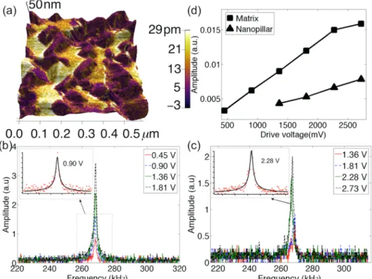
The piezoelectric response of LMN-BFO as probed by PFM is shown in Fig.2. From the PFM amplitude mapping overlaid on 3D topography shown in Fig.2(a), the correlation
FIG. 1. The structure of BFO-LMO; (a) schematic configuration; (b) cross-section TEM image; (c) three-dimensional AFM tapping mode topography mapping; and (d) MFM mapping.
FIG. 2. Piezoresponse force micros-copy (PFM) of BFO-LMO heterostruc-ture; (a) amplitude mapping overlaid on the 3D topography; and amplitude-frequency response of (b) BFO matrix and (c) LMO nanopillar at different driving voltages, with the inset show-ing DHOM fittshow-ing; and (d) corrected amplitude versus driving voltage in matrix and nanopillar.
between piezoresponse of the heterostructure and the corre-sponding topography is evident, with BFO matrix showing much higher piezoelectric strain than LMO nanopillars, as expected. To compare the piezoelectric response in a more quantitative way, PFM amplitude-frequency responses at different AC driving voltages were measured in both BFO matrix and LMO nanopillars, as shown in Figs.2(b)and2(c), which clearly exhibit resonant peaks at around 280 kHz. Approximating the cantilever-sample interaction by damped harmonic oscillator model (DHOM),10these curves can be fit-ted excellently, as seen in the insets, from which the quality factor of the system can be determined. This allows us to determine the corrected amplitudes versus driving voltages using the quality factor, as presented in Fig.2(d). It is evident that both BFO matrix and LMO nanopillars shows piezores-ponse, and the effect is more prominent in BFO, which exhib-its a nice linear curve expected in piezoelectric materials. The response of LMO, on the other hand, is smaller and requires much larger driving voltage. The appearance of piezoelectric-like response in non-ferroelectric LMO could be due to electrochemical activities of lithium ions. Furthermore, the interface between LMO and BFO is not vertical as seen in the
TEM image of Fig.1(b), and there could be BFO phase under-neath of LMO nanopillars probed, contributing to the piezoelectric-like response as well.
We then probe the piezomagnetic response of BFO-LMO heterostructure using the newly developed PmFM, as sche-matically shown in Fig. 3. The sample was put on top of a magnetic coil driven by AC current (Fig.3(a)), resulting in an AC magnetic field that excites the piezomagnetic vibra-tion of the sample, which can be magnified by resonance enhancement and measured by photodiode, as we normally do for PFM. The strength of the magnetic field can be con-trolled by the input current, with a linear correlation observed in Fig. 3(c). The PmFM amplitude mapping over-laid on 3D topography is shown in Fig.4(a), and the correla-tion between PmFM response and 3D topography of heterostructure is again evident, though the BFO matrix also shows higher response, somewhat unexpectedly. This is not totally surprising though, since BFO doped by Mn at B-site does show ferromagnetism, as reported before.4It is empha-sized here that the imaging mechanism of PmFM is based on magnetostrictive strain of ferromagnetic materials, which is usually smaller than piezoelectric strain of ferroelectric
FIG. 3. The principle of PmFM; (a) schematic configuration; (b) magnetic field induced by AC current; and (c) measured magnetic field versus input current.
FIG. 4. PmFM of BFO-LMO; (a) am-plitude mapping overlaid on the 3D to-pography; and amplitude-frequency response of (b) BFO matrix and (c) LMO nanopillars at different driving voltages, with the inset showing DHOM fitting; and (d) corrected ampli-tude versus driving voltage in matrix and nanopillar.
materials probed by PFM. To comparing the piezomagnetic responses of BFO and LMO quantitatively, the amplitude-frequency responses at different AC driving voltages were measured in both matrix and nanopillar, as shown in Figs.
4(b)and4(c), which exhibit resonant peaks around 268 kHz, slightly smaller than those of PFM. These curves can again be fitted by DHOM, as seen in the insets, from which the quality factor of the system can be determined. The corrected amplitudes versus driving voltages are presented in Fig.4(d), and it is evident that both BFO matrix and LMO nanopillars shows linear piezomagnetic response, and the effect is more prominent in BFO.
We also probed a small area of an LMO nanopillar using dual frequency resonance tracking PmFM,5with which the mappings of corrected amplitude, phase, resonant frequency, and quality factor can be derived based on DHOM, as pre-sented in Fig.5. A small portion of the points yield no solu-tion in DHMO, marked as blue background. It is noted that the corrected PmFM response is around 1 pm, and the quality factor is around 100. Some variation in resonant frequency exists, and small contrast in PmFM phase is observed, indi-cating more or less uniform magnetization state.
We close by notice that unlike PFM, which generally utilizes the localized electric field underneath AFM tip to excite the piezoelectric vibration, the current implementation of PmFM excites the specimen globally, for lacking of an effective method to induce localized magnetic field. This is a major limitation of the technique, resulting in loss of high spatial resolution and sensitivity. Cantilevers with micro-coils to generate localized magnetic field in sub-micron me-ter region has recently been reported,11and we expect it will help improve the PmFM substantially, which we hope to implement soon. The current system thus is best suited for
isolated magnetic nanostructures, wherein the interactions will be localized due to the sample geometry.
IV. CONCLUSION
In conclusion, BFO-LMO heterostructure has been probed by MFM, PFM, and PmFM. While MFM imaging show no clear distinction between these two phases, PFM and PmFM mappings show clear correlation with the topography of heterostructure, enabling us to distinguish LMO nanopillars from BFO matrix. Linear piezoelectric and piezomagnetic responses have been observed in both phases, with effects more prominent in BFO. The strong piezomagnetic response in BFO is attributed to Mn doping, while piezoelectric-like response of LMO is attributed to electrochemical activities of lithium ions as well as vertical geometry of heterostructure. The limitation of global excitation of PmFM is also discussed.
ACKNOWLEDGMENTS
The work at University of Washington was partially supported by National Science Foundation (DMR-1006194), and A.E. also acknowledges the University of Washington Clean Energy Institute Fellowship. The work at National Chiao Tung University was supported by the National Science Council, R.O.C. (NSC-101-2119-M-009-003-MY2), Ministry of Education (MOE-ATU 101W961), and Center for Interdisciplinary Science of National Chiao Tung University. S.H.X. acknowledges the support of Natural Science Foundation of China (Approval Nos. 11372268).
1W. Eerenstein, N. D. Mathur, and J. F. Scott,Nature442, 759 (2006); R.
Ramesh and N. A. Spaldin,Nature Mater.6, 21 (2007).
2
C. W. Nan, M. I. Bichurin, S. Dong, D. Viehland, and G. Srinivasan,
J. Appl. Phys.103, 031101 (2008).
3W. Liang, Y. Liu, S. C. Liao, W. C. Wang, H. J. Liu, H. J. Lin, C. T.
Chen, C. H. Lai, A. Borisevich, E. Arenholz, J. Li, and Y. H. Chu,
J. Mater. Chem.2, 811 (2014).
4M. Azuma, H. Kanda, A. Belik, Y. Shimakawa, and M. Takano,J. Magn. Magn. Mater.310, 1177 (2007); P. P. Hankare, R. P. Patil, U. B. Sankpal, S. D. Jadhav, I. S. Mulla, K. M. Jadhav, and B. K. Chougule,ibid.321, 3270 (2009).
5Q. N. Chen, F. Ma, S. Xie, Y. Liu, R. Proksch, and J. Li,Nanoscale5,
5747 (2013).
6
A. Gruverman, O. Auciello, and H. Tokumoto,Annu. Rev. Mater. Sci.28, 101 (1998).
7
M. R. Koblischka and U. Hartmann,Ultramicroscopy97, 103 (2003).
8L. Abelmann, S. Porthun, M. Haast, C. Lodder, A. Moser, M. E. Best, P. J.
A. van Schendel, B. Stiefel, H. J. Hug, G. P. Heydon, A. Farley, S. R. Hoon, T. Pfaffelhuber, R. Proksch, and K. Babcock, J. Magn. Magn. Mater.190, 135 (1998).
9S. Jesse, A. Kumar, T. M. Arruda, Y. Kim, S. V. Kalinin, and F. Ciucci, MRS Bull.37, 651 (2012).
10
S. Xie, A. Gannepalli, Q. N. Chen, Y. Liu, Y. Zhou, R. Proksch, and J. Li,
Nanoscale4, 408 (2012).
11C. Mousoulis, T. Maleki, B. Ziaie, and C. P. Neu,Appl. Phys. Lett.
102, 143702 (2013).
FIG. 5. The DFRT PmFM mapping of a small area of an LMO nanopillar; (a) corrected amplitude; (b) quality factor; (c) resonant frequency; and (d) phase.