IEEE TRANSACTIONS ON COMMUNICATIONS, VOL. 39, NO. 8, AUGUST 1991 1197
Transactions Papers
Minimum Mean-Squared Error Decision-
Feedback Equalization for Digital Subscriber Line
Transmission with Possibly Correlated Line Codes
David W. Lin, Senior Member, IEEE
Abstract- Most of the published theory on the optimal per-
formance of decision-feedback equalization under the MMSE criterion addresses the transmission of i.i.d. symbol sequences only. This paper presents a theory which accommodates the case of correlated symbol sequences. It also considers the use of a fractionally spaced forward filter in the decision-feedback equalizer (DFE). Two limiting conditions are discussed in some detail, both concerning having an infinite-length DFE feedback filter. In one of them the forward filter is of finite length and in the other it is noncausal infinite. Several numerical examples are given, in which we apply the theory to the study of the MMSE transmission performance, at ISDN basic access rates, of a few example subscriber lines using some well-known line codes. In these examples, the near-end crosstalk from identical digital transmission systems is assumed to be the only significant noise. Throughout the study, we ignore the effects of error propagation in a DFE.
I. INTRODUCTION
ECISION-FEEDBACK equalization for data transmis-
D
sion over dispersive channels has been a topic of contin-ued study for some time [l]. Somewhat earlier applications include a high-rate coaxial transmission system [6] and a military tropospheric scatter radio system [7]. More recently, it has been used in digital subscriber line (DSL) terminals to support the ISDN (integrated services digital network) basic access over twisted-pair cables [8], [9]. Our interest here is in understanding its optimal performance, in the minimum mean-squared error (MMSE) sense, in the DSL environment. Despite the amount of previous studies concerning decision- feedback equalization [l]-[SI, we find the published theory unable to address our need fully. A major reason is that the published theory on MMSE equalization largely addresses the transmission of i.i.d. (independent and identically distributed) symbol sequences only, whereas in the area of DSL there has been a long standing interest in line coding schemes which yield non-i.i.d. outputs. More recently, Lechleider [ 111 aug- mented the theory to accommodate also the case of correlated
Paper approved by the Editor for Channel Equalization of the IEEE Communications Society. Manuscript received February 6, 1989; revised November 15, 1989 and March 29, 1990.
The author is with the Department of Electronics Engineering and the Center for Telecommunications Research, National Chiao Tung University, Hsinchu Taiwan 30050, ROC, on leave from Bellcore, Ked Bank, NJ 07701.
IEEE Log Number 9100820.
symbol sequences. The present author [12] also reported a study which not only considered correlated symbol sequences, but also allowed for a fractionally spaced forward filter in the DFE (decision-feedback equalizer). However, these publi- cations are concerned with finite-length DFE’s only. McGee [ 101 considered infinite-length DFE’s in correlated symbol sequences. However, he assumed their analog front-ends to be optimal, a common assumption which in practice can only be approximated at best and one which we do not make in this study. Further, the extension of his results to the conditions we are interested in is not an obvious matter.
The performance of an infinite-length DFE is of interest although practical DFE’s are always of finite lengths. This is because it provides information on the limit of MMSE equalization and can serve as a benchmark against which the performance of a finite-length DFE may be compared. To some extent, we can liken its role to that played by the channel capacity in the design of communications systems. Now, the input to the feedback filter is a digital signal with only a very limited number of levels, while that to the forward filter is continuous in amplitude. Hence it is more difficult to implement a long forward filter than a long feedback filter, due to the amount of multiplication required with the former. Thus, for the sake of benchmarking at least, it is of interest to study the performance of MMSE decision-feedback equalization in the limit of an infinite-length feedback filter, while holding finite the length of the forward filter. This limiting case is addressed in this paper, as well as that of having an infinite- length feedback filter with an infinite-length forward filter, both in the situation of correlated symbol sequences.
In summary, therefore, the aim of this paper is twofold. First, to present a theory on MMSE equalization for DFE’s (especially infinite-length ones) operating in correlated symbol sequences; and second, to illustrate their performance in the DSL environment by way of some numerical examples.
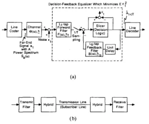
Schematically, the equalization problem considered can be pictured as in Fig. l(a) where the “channel” includes all analog transmission filtering, as depicted in Fig. l(b) for the case of DSL transmission. (Hybrids are transformer circuits for coupling transceivers with the transmission line. An example will be shown later.) For generality, the DFE forward filter
1198 IEEE TRANSACTIONS ON COMMUNICATIONS, VOL. 39, NO. 8, AUGUST 1991 Decision-Feedback Equalizer Which Minimizes E E f
r _ _ _ _ _ _ _ _ _ _ _ _ _ _ _ _ _ _ _ _ _ Delay by
c Symbal
*
a t c T PeriodsPeriods
Far-End Lf-tap
Signal a Channel Forward
E t
Noise xt
Fig. 2. A mathematically equivalent problem when the DFE slicer makes no decision error.
Transmit Fig. 2, we can write down an expression for the mean-squared
decision-point error. For this, note first that the combined impulse response of the channel and the DFE forward filter
a lower triangular Toeplitz matrix having h as its first column
(padded with trailing zeros as needed), K is an Lf-column
Filter
( b)
Details of the channel.
Fig. 1. The MMSE equalization problem. (a) Problem frame work. (b) is, after T-spaced given by M f H K h f where H is
is assumed to be possibly fractionally spaced with a temporal tap spacing k T l m where T is the symbol period and IC and
m are coprime integers with
k
5
m , including the casek
=m = 1. In Fig. l(a),
b
denotes the vector of channel impulseresponse sampled at T/m spacing and 0 the corresponding
frequency response, i.e., @(U) = hie-jiwTlm where
we have let = [ho,hlh2,.
.
.]’,
with’
denoting matrixtranspose. The noise x is also assumed to be sampled at T / m
spacing. The vectors
hf
and&
represent, respectively, the impulse responses of the kT/m-spaced DFE forward filterand the T-spaced DFE feedback filter, while F and B the
corresponding frequency responses. We have also assumed an overall transmission delay (cursor delay) of c symbol periods. Note from Fig. l(a) that, unlike in some earlier studies [2]-[SI, [lo], we do not consider the analog front-end as part of the DFE. In other words, we assume the response of the analog front-end to be fixed and not optimizable. This is because analog filters are less easily made adaptive to minimize the MSE (mean-squared error) as shown.
In the following, Section I1 outlines a general solution to the MMSE decision-feedback equalization problem. It serves to establish some notions for later use. Section 111 then develops the results to address the case of an infinite-length feedback filter with a finite-length forward filter, and Section IV the case where both the forward and the feedback filters are infinite in length. Section V applies the theory to a few example subscriber lines to investigate their transmission performance under MMSE decision-feedback equalization. Section VI concludes the paper. In this work, the problem of error propagation in DFE’s is not addressed.
matrix whose
ik
+
1st column is the i k+
1st column of the identity matrix (i = 0 , 1 , 2 , .. .
,
L f - l ) , and M is a matrixwhose zk
+
1st column is the i m+
1st column of the iden-tity matrix ( i = 0 , 1 , 2 , .
.
.) [12]. The MSE is thus given by (assuming a certain given cursor delay c)E(&fT’,lhf,&} = E ( [ ( M ‘ H K h f - P&
-e,)’
’ !&T
+
b;K’g;T]2}= ( M ‘ H K b f - P ~ L , - 5)’Ra
.
( M ’ H K L f - P b - G )+
h;K‘R,Khf(1)
where E denotes expectation;
ai,
and giT are, respectively,vectors of far-end signal symbols and noise samples, arranged in reverse time order and led by C L ~ T and Z~T, respectively, R,
and R, are the corresponding autocorrelation matrices;
e,
is the c+
1st column of the identity matrix; andP
is a matrix composed of the c+
2nd through the c+
Lb+
1st columns of the identity matrix.All of the vectors and matrices in (1) can be of infinite
dimension. Also, note that M’HK is basically block Toeplitz
with IC x m-sized blocks. Further, if the channel noise is dominated by self-NEXT (near-end crosstalk from identical
DSL systems), then, by the Tlm-spaced sampling of E, the
matrix R, is either Toeplitz or block-Toeplitz with m x m-
sized blocks; and so is K’R,K.
Minimization of the MSE involves a straightforward ex- ercise of the least-squares technique [12], which yields the following MMSE DFE:
byt
= RT’pl, ( 2 411. MMSE DECISION-FEEDBACK EQUALIZATION -
hTt
= ( P ’ R , P ) - l P ’ R , ( M ’ H K h ~ t - G), (2b)As often done, we assume that the slicer in the DFE makes no incorrect decisions, which should be approximately true during normal operation at a low error rate. Then the transmission path is mathematically equivalent to the one shown in Fig. 2. Assume further that the signal and the
and the MMSE:
e min
E{E?Tlbf
,h}
hf ’ h b
LIN: MMSE DECISION-FEEDBACK EQUALIZATION 1199
where
and
(i.e., the far-end signal power). In writing (2)-(4), we have
assumed the invertibility of R1 and P’R,P which can be
shown to hold for finite-length DFE’s. The invertibility may be a concern for infinite-length DFE’s and it will be addressed in later sections. Also, note that (2)-(4) simplify significantly when we have uncorrelated symbol sequences, i.e., when
R, = 0 : I . (For simplicity, we shall use the same notation
Z to denote identity matrices of different dimensions, when
confusion is unlikely.)
After equalization, the nominal SNR (signal-to-noise ratio)
is given by oi/o,”. It can be used to measure the transmission
performance, subject to the concerns discussed in [ 121, such as the possible signal-dependence of noise variance. For no- tational simplicity, hereafter we omit the superscript opt from hopt and
hipt,
because all subsequent references tobf
andhb
-f
are to their MMSE values.
111. DFE WITH AN INFINITE-LENGTH FEEDBACK FILTER AND A
FINITE-LENGTH FORWARD FILTER
To apply the MMSE solution to the case of an infinite- length DFE feedback filter, note first that the matrix
P
in thiscase is semi-infinite and so is P’R,P. By the Toeplitz nature
of R,, we have P’R,P = R,. It is trivial to invert R,
when it is diagonal. For many line codes, however, it is not only nondiagonal but also singular because of the deliberately designed spectral zeros on the unit circle [14]. Examples of such codes are the precoded dicode (or bipolar, or AMI) [15], the precoded MDB (modified duobinary, or class-4 partial-
response) [15], and the MS43 [16], [17] codes. For them
the use of inverse of P’R,P in the MMSE solution has
to be reexamined. In MMSE estimation with a finite-length estimator, a convenient tool to handle this kind of problem is the generalized matrix inverse [18], [19]. It turns out that, in our case, we can also define a special kind of matrix inverse for
R, to make valid the solution as formulated in (2)-(4). This
inverse can be described in terms of a spectral factorization [20], [2] of S,(w), the power spectrum of the far-end signal.
To this end, let
{w,}
be a zero-mean Gaussian randomsequence whose power spectrum is equal to S,(w) also. Then
{vi} can be represented as a causal moving average of a white sequence {U,} as v, = U,
+
p 1 ~ , - 1+
~ Z U , - Z+
. . .. Thesequences {U,} and { p , } are related to
S,(w)
asdenote a spectral factorization of S,(w). It is not hard to show
that
R , = 0;rrrI (6)
where
II
is a lower triangular Toeplitz matrix whose firstcolumn is given by [ l , p l , p ~ , . . . ]
’.
Now, let { l . q l r q 2 , . . . } be the causal inverse of { l , p l . p 2 , ..
.}, i.e., & ( U )E,”=,
q,e-JZwT =&,
with qo 1. (The system & ( U ) ismarginally stable when S, (w) contains spectral zeros.) The
sequence { -41, - 9 2 , .
.
.}, in fact, gives the infinite-order one-step linear MMSE predictor for the process {vz} and
02
isequal to the variance of the infinite-order one-step prediction error. We are now ready to define the special kind of inverse for R,, denoted RL:
(7) where Q is a lower triangular Toeplitz matrix with its first column given by [l, 41, q 2 ,
. .
. ] I . Proof that the use of thisinverse in (2)-(4) does result in the desired MMSE solution for the problem will be omitted here. Simply put, it involves a verification of the equivalence of the range subspaces of some singular linear transformations, much the same as in the case of generalized matrix inverses.
The evaluation of o? and p , for the various line codes is not a difficult task. For a partial-response code, { p , } is simply given by the partial-response filter and 02 the power
of filter input. For a block code, its power spectrum is a finite-order rational function in the Z-transform domain and can be calculated by an established method [17]. The spectral factorization can thus be done by factoring the numerator and the denominator of that function, followed by a long division.
As a numerical example, Table I gives the power spectrum of
the MS43 code and its spectral factorization.
To calculate the MMSE solution as given in (2)-(4), then, we note that, by (6) and (7),
R, - R,P(P’R,P)~P’R, = o ; ~ I ’ ( I - P P ’ ) ~ I (8)
which is everywhere zero except for the leading (c
+
1) x( c
+
1) submatrix. In fact, this matrix can be interpreted as the autocorrelation of error in estimating the infinite vector [vz, v,-1. v1-2.. .
.I’
from {w,-,-1, vZ-,-2,..
.} by alinear (matrix) MMSE estimator. The quantity of 0: -
eLR,P(P’R,P)tP’R,g, appearing in (3) is simply the
c
+
1st diagonal element of the above matrix and is equal to ~72. (These results can also be derived using the notion ofinnovations [20]. ) Therefore, the MMSE can be expressed as
1200 IEEE TRANSACTIONS ON COMMUNICATIONS, VOL. 39, NO. 8, AUGUST 1991 TABLE I
POWER SPECTRUM OF THE MS43 CODE AND ITS SPECTRAL FACTORIZATION
Power Spectrum Denominator = Numerator = 22.4. [ ( z 6
+
z - ~ )+
9.225(z3+
z - ~ ) - 29.23906253 - (2+
E - * )-
6.8(zi+
E-’) +69(z6+
z - ~ )-
17.465(z5+
z?) - 70.66(z4+
E - ~ )+
592.425(z3+
z - ~ )+
14.6075(z2+
z - ’ )+
2 9 2 . 2 5 5 ( ~ ’+
Z - ’ ) - 1744.725 Spectral Factorization Error Variance = Denominator = Numerator = Series Expansion = 2.1944 1 - 0 . 3 7 5 ~ ~ ~ - O.0390625rK6 1 - 0 . 3 4 9 5 2 ~ - ’ - 0.16995~-’ - 0 . 4 7 9 8 6 ~ ~ ’+
0 . 0 4 6 7 6 4 ~ - ~ - 0.0031980~-’ - 0 . 0 5 2 7 1 3 ~ - ~+
0 . 0 0 5 6 8 1 6 ~ - ~+
0 . 0 0 0 7 9 4 6 9 ~ - ~ 1 - 0 . 3 4 9 5 2 ~ ~ ’ - 0 . 1 6 9 9 5 ~ 5 ’ - 0.10486zC3 - 0 . 0 8 2 3 0 6 ~ - ~ - 0.066928~-’ - 0 . 0 5 2 9 7 4 ~ - ~ - 0.038836;-‘ - 0 . 0 3 0 9 4 2 ~ ~ ~ - 0.023961~-’ - 0 . 0 1 7 7 7 9 ~ - ’ ~ - 0.014218~-” - 0 . 0 1 1 0 5 5 ~ ~ ~ ’ - 0 . 0 0 6 1 8 4 0 ~ ~ ’ ~ - 0 . 0 0 6 5 4 0 3 ~ ~ ’ ~ - 0 . 0 0 5 0 8 1 5 ~ - ’ ~ - 0 . 0 0 3 7 6 3 5 ~ - ~ ~ - 0.0030080~-” - 0 . 0 0 2 3 3 7 4 ~ - ~ ~ - 0 . 0 0 1 7 3 1 0 ~ ~ ’ ~ - 0 . 0 0 1 3 8 3 5 ~ - ~ ~ + . . . m-1 l O ( W . ) 1 2The optimal DFE forward filter is again given by
hf
= Rclpl.The optimal DFE feedback filter can be shown by using (6)
and (7) in (2b) to be
factorization of 1
+
S,(w) .$
(where w, =+
+) in the Sense that&
= W ’ r I ( M ’ H K I L f-
g c ) .By the Toeplitz nature of
Il
andXP,
multiplications with them can be viewed as convolutions and carried out in the frequencydomain by multiplying with P ( w ) and & ( U ) . The possible The MMSE feedback filter is given by
existence of unit-circle poles in & ( U ) , due to the spectral zeros
of Sa(w), causes no stability problem because these poles are
canceled by the corresponding zeros of €‘(U).
Iv.
DFE WITH BOTH FILTERS INFINITE IN LENGTHWe now consider a DFE whose forward and feedback filters
are both infinite in length. As mentioned, this DFE structure
has been studied in various contexts short of what we are
interested in [ 2 ] , [4], [lo]. And the extension of these previous results to our situation is not an obvious matter.
As in the earlier studies, we assume the forward filter to be noncausal, i.e., infinite in both directions of time, while the feedback filter strictly causal and semi-infinite. In terms of our time-domain formulation given in the previous sections, this
DFE structure can be considered as first letting the cursor delay
c + CO, letting the forward-filter length
L f
= 2 c m / k ---t CO, and then shifting the time origin to where the cursor is. After the shift of time origin, the cursor delay becomes zero relative to the new “time zero” and the forward filter becomes noncausal and two-sided infinite.Due to its length and mathematical nature, we leave the
derivation of the MMSE solution to the Appendix. Below
we summarize the results for the situation where IC = 1,
assuming that the sampled noise process x is stationary and
letting
Sx(w)
denote its power spectrum. In this situation, theMMSE forward filter is given by, in the frequency domain,
a:a;O*(w)P*(w)y*(w)
S X (U)
F ( w ) = (11)
where
*
denotes complex conjugation, U: and P ( w ) aredefined in the last section, and U: and y ( w ) define a spectral
And the MMSE is simply
2 - 2 2 uc - u,cTy.
-
llA comparison of (11) with the earlier results concerning
i.i.d. symbol sequences, such as those in [4], reveals that the difference lies mainly in the presence of ~7: and P ( w ) . In fact,
front-end of the conventional MMSE DFE[4]. Note also that
neither P ( w ) nor y ( w ) is needed in calculating the MMSE uf and hence the nominal SNR a ~ / a ~ , but only U: and :;U
of which the latter can be evaluated from A(w) using the
well-known equality that [21], [22], [2]
the factor o * ( w ) p * ( w ) in ’ (1 1) corresponds to the matched-filter
s= ( w )
and the former from S,(w) by the technique of rational-
function factorization described earlier.
Interestingly, a simple expression exists for each of the
two constituents of the MMSE, viz., the filtered channel-noise
power and the equalization error power. The former is given by
-
TABLE I1
SYMBOL ERROR RATE VS. REQUIRED SNR (IN DB) FOR SOME LINE CODES IN TRANSMISSION OVER A GAUSSIAN NOISE CHANNEL
Line Code -+ Precoded Dicode,
1 Error Rate “2 Precoded MDB MS43 3B2T 2B1Q
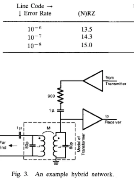
10-6 13.5 lo-‘ 14.3 10-8 15.0 16.7 17.5 18.1 ~ 17.8 18.4 20.7 18.5 19.2 21.4 19.2 19.8 22.1 900
Fig. 3. An example hybrid network
V. NUMERICAL EXAMPLES
As examples, we consider the DFE performance on the six loops (subscriber lines) used in a previous study [13]. As in [13], we also consider two simple 26-gauge PIC (polyethylene- insulated cable) lines of lengths 2.5 and 3 miles, respectively, for a comparison. Although we shall sometimes refer to this effort as a simulation, we do not mean a “real” simulation done in a sample by sample fashion. Instead, the above-developed theory is used to calculate the numerical results.
We consider the following six line codes: (N)RZ ([non-] return-to-zero - coding 1 as +1 and 0 as -1; waveform re-
turns or does not return to zero depending on the duty cycle) [24], dicode (precoded), MDB (precoded), MS43, 3B2T (3
binary-to-2 ternary, excluding 00), and 2B1Q (2 binary-to-
1 quaternary). Table I1 lists the required SNR for symbol
detection in signal-independent additive Gaussian noise for these codes at several symbol error rates. (This table is more accurate than Table I of [12].) We let the bit rate be that considered for the ISDN basic access, i.e., 160 kbls, except in the case of the 3B2T code where for divisibility by three we let the bit rate be 162 kb/s.
The simulated hybrid network has the configuration shown in Fig. 3 where the 1 p F capacitors are for DC blockage. Interestingly, we have found the 900 R resistance to result in a better SNR performance than the 135 R used in some studies, although the latter is closer in value to the characteristic impedance of the lines at the considered frequencies. This could be due to the combined effect of various factors which we do not intend to analyze here. The transformer windings
are assumed to be perfectly coupled so that M = L . Two
values of L are considered, namely, L = 40 mH and L =
3.5 mH. (This hybrid network only serves as an example and is in no way claimed to be the best design. Same is true for the transmission filters to be described later.)
The impulse responses of the loops have been calculated
as described in [13]. As in (131, we have assumed their
frequency responses to be negligible beyond twice the baudrate
in each case-equivalent to assuming brickwall low-pass
filtering with a cutoff at twice the baudrate. Because of this we have not included an antialiasing low-pass filter in the simulated transceiver. The combined characteristics of the transmit and the receive filters are the same as the 21-tap FIR filter described in [13], in series with a first-order analog high- pass filter. Data symbols are transmitted with a 25% duty cycle because the FIR filter operates at 4 times the baudrate. We let the corner frequency of the first-order analog high-pass filter be variable with the line code and the DFE length. For each line
code and each DFE length, it is determined by choosing from a
set of frequencies the one yielding a better SNR, where the set consists of seven frequencies at, respectively, 0, 0.025, 0.05, 0.1,0.15,0.2, and 0.25 times the baudrate. (A corner frequency at 0 means a flat unity gain, i.e., no high-pass filtering.) It happens that this chosen frequency has been zero in all the examples presented below.
The noise is assumed to be dominated by self-NEXT which
is known to have a power transfer function
Kf3I2
wheref
is the frequency in Hz and K is a parameter dependingon the crosstalk strength [25]. Further, we assume that the composite self-NEXT noise is stationary (instead of merely cyclostationary as the digital waveform in each individual crosstalking system is). Also for simplicity, we arbitrarily
assume that the crosstalkers consist solely of 2 mile 26
gauge PIC lines. (The results from assuming 2 mile 26 gauge
crosstalkers composed of pulp-insulated lines differ from those obtained under the above assumption by less and 0.1 dB in
all examples below.) We let
K
= which correspondsroughly to the 49 crosstalker curve in [26]. (The data presented in [26] were obtained through computer simulation of crosstalk in 18 kft 22 gauge PIC lines which were terminated in their characteristic impedance. Although this condition is different from ours, we should have been conservative by using its data, at least for the two reasons below. First, 26 gauge lines incur more loss per unit length than 22 gauge ones and hence the crosstalk power will probably be lower on the average. And second, the data in [26] are for severe NEXT disturbance which has only 1% cumulative probability of occurrence.)
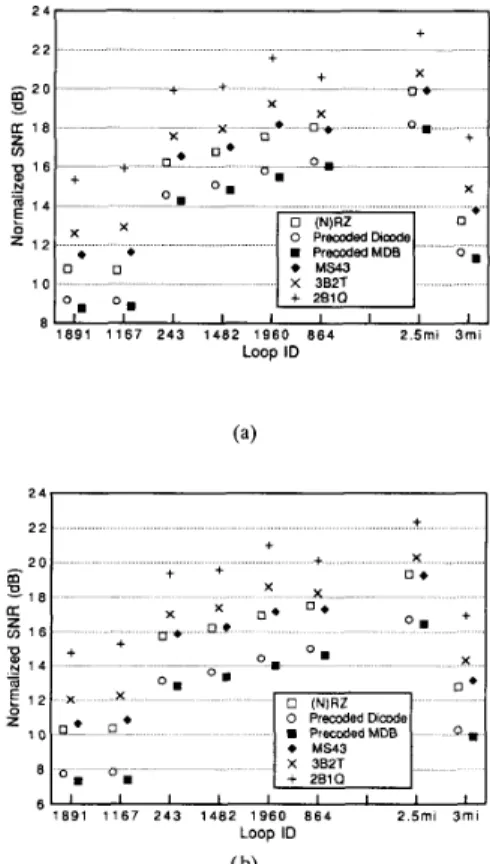
Consider now the situation of a DFE having a noncausal infinite-length T12-spaced forward filter and a semi-infinite
feedback filter. For it we obtain a better result with L = 40 mH
than with L = 3.5 mN. Fig. 4 shows the result from having
L = 40 mH where for ease of comparison we have normalized
the SNR values with respect to that required for a symbol
error rate. In other words, we have subtracted 14.3, 17.5,
1202 2 4 2 2 s 2 0 F. a: 1 8 In U 1 6 - B + 2 4 +
1
+ + + X + + U * X O = + x D * 0. 0 . X 0. 1 4 0 (N)RZ 0 Premdedhmde X 3B2T + 2810 D O ' 8 ' 8 1 0 8 8 I I I I I I I I - !!1 6 PremdedMDB MS43 X 3B2T z" 1 4 1 2 - 0 % 2 5mi 3 m i 1 8 9 1 1 1 6 7 2 4 3 1 4 8 2 1 9 6 0 8 6 4 1 0 Loop ID 2 2 g 2 0 K-
Fig. 4. Transmission performance (subscriber to central office) with an MMSE DFE having an infinite T/2-spaced forward filter and a semi-infinite feedback filter. + + E X c a * i + +
coded dicode, the MS43, etc., respectively; so that, if the
decision-point error E is Gaussian and signal-independent, than
a 0 dB normalized SNR corresponds to a symbol error rate. We have also included a very small amount of band-
limited white noise in x to avoid the need to handle division by
zero in the computation of A ( w ) which would otherwise arise
sometimes. This should not have caused appreciable difference in the result. In obtaining the result, we have also otimized the receiver's timing by considering 16 equispaced candidate sampling phases and picking the one yielding the minimum
MMSE. As seen, in Fig. 4 we have ordered the six loops
according to ascending SNR performance.
Interestingly, the MMSE performance obtained using a T-spaced forward filter is effectively the same as that using a T/2-spaced: the difference being less than 0.1 dB in all code and loop combinations. With a moderately suboptimal timing phase (&1/16 of a symbol interval away from the optimal), the performance of the T/2-spaced equalizer stays intact, and that of the T-spaced suffers little (less than 0.1 dB in all cases), too. The performance difference becomes more conspicuous with a more suboptimal timing phase, however. For the T-spaced equalizer, a f 1 / 4 symbol interval's phase offset from the optimal leads to a performance degradation of up to about 0.85 dB and a &1/2 symbol interval's offset one of up to 2.7 dB; while for the T/2-spaced equalizer, less than 0.05 dB of maximum degradation is caused in these situations. This echoes the frequently observed result that fractionally spaced equalizers suffer less from timing suboptimality than synchronous ones in diverse situations in a different context.
We now shorten the forward filter to finite lengths but keep the length of the feeback-filter infinite. Fig. 5 depicts some
results, again with L = 40 mH because it yields a better
performance. The forward filters are again T/2-spaced. The decision delay has again been optimized up to 1/16 of a symbol period in each case. Fig. 6(a) plots the reduction in
MMSE SNR from using an infinite-length forward filter to
using an 8-tap one, and Fig. 6(b) that from using an 8-tap forward filter to using a 3-tap one. It is interesting that the
SNR reduction for each code is quite even across the different
loops in either situation.
As may be expected, timing suboptimality now exerts a
greater influence on the equalizer's SNR performance for these
IEEE TRANSACTIONS ON COMMUNICATIONS, VOL. 39, NO. 8, AUGUST 1991
2 4 2 2 2 0 O l 6 f 1 6 U - $ 1 4 1 2 1 0 8 6 s a z + + + x + + D * X X 0 PremdedDimde X 3B2T + 2B1Q 2 5mi 3 m i 8 9 1 1 1 6 7 2 4 3 1 4 8 2 1 9 6 0 8 6 4 Loop ID ( b)
Fig. 5. Transmission performance (subscriber to central office) with an MMSE DFE whose feedback filter is semi-infinite in length and whose forward filter is T/2-spaced. (a) Length of forward filter = 8. (b) Length of forward filter = 3. 2 5 1 c 5 1 5 E l 0 + + Loop ID (a) $j 1.5 $ l C ,E 0.:
-
a c 5 1 8 9 1 1 1 6 7 2 4 3 1 4 8 2 1 9 6 0 8 6 4 2 . 5 m i 3 m i Loop ID ( b)Fig. 6. Reduction in transmission performance from shortening the DFE forward filter. Feedback filter is semi-infinite in length. (a) As forward filter is shortened from of infinite length to 8 taps. (b) As forward filter is shortened from 8 taps to 3 taps.
shorter forward-filter lengths than for a length of infinity. With a &1/16 symbol interval's phase offset, a worst case SNR
I
LIN: MMSE DECISION-FEEDBACK EQUALIZATION 1203
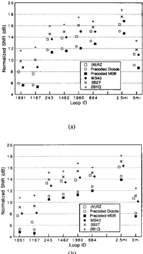
+ X I + x o * ‘ 8 c + x * n o * U * a + + x U * I I I I I I I I I 1 891 1167 2 4 3 1482 1960 8 6 4 2.5mi 3 m i Loop ID 2 5ml 3 m i 891 1167 2 4 3 1482 1980 8 6 4 L o o p ID ( b)
Fig. 7. Transmission performance (subscriber to central office) with an MMSE DFE whose feedback filter is 30-tap long. Forward filter is T/2-spaced. (a) Length of forward filter = 8. (b) Length of forward filter = 3.
is found in the 8-tap situation, and one of 2.0 dB in the 3-tap situation.
Finally, let us shorten the feedback filter length to 30 taps while keeping the forward-filter lengths at 8 and 3 taps. This
time we get a better performance with L = 3.5 mH. The
corresponding result from using optimal decision delays is
shown in Fig. 7. Fig. 8(a) plots the SNR reduction from having
an infinite-length feedback filter to having a 30 tap one, at a forward filter length of 8 taps; and Fig. 8(b) that from having an 8 tap forward filter to having a 3 tap one, at a feedback- filter length of 30 taps. On the effect of suboptimal timing, we
find a worst case degradation of 0.65 dB among all code and
loop combinations in the situation of an 8 tap forward filter, and one of 2.25 dB in the situation of a 3 tap forward filter, again at a *1/16 symbol interval’s offset from the optimal delay. It is likely that timing suboptimality will cause a worse degradation if we further shorten the feedback filter [27].
It is interesting to note that, in all these examples, the
transmission performance is reversely related to the baudrate, except in the case of the simple (N)RZ, which often performs as well as the MS43.
VI. CONCLUSION
We presented a theory on MMSE decision-feedback equal- ization which augments previously published results by al- lowing both a correlated symbol sequence and a fractionally spaced DFE forward filter. This theory facilitates our calcu-
4 . 0
- I
I + + ++
+ I
E I o “1891 1167 243 1482 1960 8 6 4 2 5ml 3 m i Loop ID 6 1.5, 0 I Loop ID ( b)Fig. 8. Reduction in transmission performance from shortening the DFE. (a) As feedback filter is shortened from of infinite length to 30 taps, at a forward filter length of 8 taps. (b) As forward filter is shortened from 8 taps to 3 taps, at a feedback filter length of 30 taps.
lating the potential DSL transmission performance in cases of correlated line codes, especially for situations where one or both of the DFE filters are infinite in length. The situation of an infinite-length DFE is of interest because it provides information on the limit of MMSE equalization and can thus serve as a benchmark against which the performance of a finite-length DFE may be compared.
We also presented a few numerical examples on the per- formance of MMSE decision-feedback equalization in DSL transmission at ISDN Basic Access rates with several well- known line codes. Interestingly, the calculated performance is inversely related to the transmission baudrate, except in the case of the simple (N)RZ code, which frequently performs as well as the MS43.
APPENDIX
MMSE SOLUTION WHEN BOTH DFE FILTERS ARE
INFINITE IN LENGTH
Although in this case it is possible to formulate and solve the MMSE problem in the frequency domain, starting with the time-domain formulation is no less convenient and avoids the introduction of some new notions. Thus, we shall proceed by
further developing (9),
(lo),
and (2a). A frequency-domainexpression of the solution will surface in the process. The shift of time origin moves us to a new viewpoint for comprehension and evaluation of the above equations. First, consider the matrix R I . As the forward filter is now
(two-sided) infinite, the quantities R,, H , 11, I , K , and M
are “full-plane’’ matrices which are (two-sided) infinite in both row and column dimensions. Indexing of their rows and columns can be more conveniently done using both positive and negative integers, with the “center” rows and columns (those corresponding to time zero) indexed by zero. The
I
1204 IEEE TRANSACTIONS ON COMMUNICATIONS, VOL. 39, NO. 8, AUGUST 1991
quantity
P
is a half-plane matrix, infinite column-wise andsemi-infinite (to the right) row-wise. Its negative- and zero- indexed rows are all equal to zero and its positive-indexed rows form an identity matrix. Its leading column corresponds to time zero. For p l , the vector
e,
is now infinite and is everywhere zero except for a unity zeroth element. By the upper-triangular nature of K ’ H ’ M andII’,
the nonzero elements of p , are confined to the “anticausal” half.To obtainthe MMSE solution, an immediate problem is
the computation of RTl. (As in Section 111, concern over its
invertibility will go away as we later consider spectral factor- izations. Similar is true for ( K ’ R , K ) - ’ below.) We appeal to
the following well-known identity for matrix inversion: ( X
+
Making the identifications that X = K’R,K, Z = &$I. and
Y = W’ = K’H’MII’(I - P P ’ ) , we get RT1 = (K’R,K)-l - O : ( K ’ R , K ) - ~ K ’ H / M I I I ’ Y z W ) - 1 = x-l -
x - ’ y ( z - l +
W x - l Y ) - 1 w x - 1 . ‘(I
- P P ’ ) @ ( I - PP’)rIM’HK(K’RzK)-l (A.1) where @ = [I+
cci(I- PP’)IIM’HK(K’R,K)-l.
K ’ H ’ M I I ’ ( I - P P ’ ) ] - l . (A.2)Simple algebraic manipulations then lead to
hf
=RT1pl
= n:(K’R,K)-lK’H’MII’(I - P P ‘ ) @ g ,04.3)
and
2
E =2
U - -p i R T 1 p , = u:gb@e,. (A.4)Equations (A.2)-(A.4) appear formidable and, at the first sight,
it may seem that we have complicated the problem rather than
simplfied it. However, the matrix @ exhibits an interesting
structure and, if the noise autocorrelation matrix K’R,K is
Toeplitz or block-Toeplitz, then @ and the MMSE solution can
be evaluated with available techniques.
Consider first the evaluation of @. To start, note that, if
K’R,K is (block) Toeplitz, then (K’R,K)-l is also (block)
Toeplitz. Thus, since IIM’HK is (block) Toeplitz, the factor
rIIM’HK(K’R,K)-lK’H’MII (denoting it by A below
for short) in (A.2) is a full-plane (block) Toeplitz matrix. Its pre- and postmultiplications by I - P P ’ simply zero out all
elements outside the upper-left “quadrant.” Hence @-’ is the direct sum of a semi-infinite (block) Toeplitz matrix and a semi-infinite diagonal matrix, where only the former enters
into the final expressions for the MMSE solution because of the pre- and postmultiplications by
e,
and I - P P ’ in (A.3) and(A.4). By its (block) Toeplitz nature, inversion of this semi- infinite matrix can be achieved by way of (matrix) spectral factorization.
To further specify this factorization, we limit our scope
by assuming that the sampled noise process 5 is stationary
and let S z ( w ) denote its power spectrum. Then K’R,K
is indeed Toeplitz and is associated with a power spectrum
k
s,
(w,,/k) where we have defined w, w +27rr/T.A frequency-domain expression of @ can be obtained by
first noting that the quantity H K ( K ’ R , K ) - l K ’ H ’ has an
associated matrix power spectrum as shown at the bottom of
the page, where
*
denotes complex conjugation and @,(U) =@(w)eJ””T/”. Therefore, the quantity M ’ H K ( K ’ R z K ) - l K ‘ H ’ M is associated with a k x k matrix power spectrum whose ijth element is given by
1 - m m-1
c
p= oNow, the matrix
II
can be viewed as a block Toeplitz matrixwith k x k blocks and associated with a matrix transfer
function whose ijth element being P i - - I ( w q / k )
where P,(w) = P ( w ) e 7 p d T . Hence, the matrix power
spectrum associated with the quantity A is given by
[+
C P , - ~ ][A
-1
[+
P:-,]’. Call itW(w) for short. Then the matrix power spectrum associated
with the upper-left quadrant of
a-’
is given by I+
a;W(w).Note that W(w) reduces to a scalar in some cases, for example, when IC = 1 or when the channel bandwidth is less than
&
(so that no aliasing occurs in the DFE forward filter).Let I
+
o,’,W(w) be spectral factorized asI
+
c,”,W(w) =[V’(w)]-’D-’[V*(w)]-’.
( A S )where D is a k x k diagonal matrix and V(w) is of minimum
phase [20] and has a series expansion whose leading term
is lower-triangular with unity diagonal elements. To further relate this to @, it is convenient to define a permutation
operator J which “reverses the time” for a k-vector sequence.
In other words, J is a block antidiagonal matrix with k x k
LIN: MMSE DECISION-FEEDBACK EQUALIZATION 1205
of
a-’
is thus turned into the lower-right quadrant in J Q - l J .Denote this semi-infinite matrix by 5-l. By the summetry
of Q-l.5-l is associated with a matrix power spectrum
I
+
a : W ’ ( w ) . Thus-
cp =
rnr’
(A.6) where A = d i a g ( D . D , . . .) andr
is the lower-triangular block Toeplitz matrix associated with V ( w ) .r
has k x kblocks and unity diagonal elements.
Therefore, from (A.4) we have the MMSE as
where a; denotes the leading diagonal element in D . From
(A.3) we have the MMSE forward filter as
where y*(w) is the leftmost column of V * ( w ) .
[*
P:-J]is a shorthand for the k x k matrix whose 23th element
is given by
Ckz;
P:pJ ( w p / ~ ) . and[+
O r k t 7 ] is a shorthand for the k-vector whose zth element is given byE,”=:
O?,,, ( w m p / k ) . with 15
iI
k and 15
j5
IC. For the MMSE feedback filter, we note first that from
(A.3) the quantity I I ( M ’ H K b f ) in (10) corresponds to
a transfer function a:a:W(w)y*(w). From (AS) we get
a:crZW(w)r*(w) = - [ ( U ) - a?y*(w) where ( ( U ) is the leftmost column of [ V ’ ( w ) ] - ’ . Now, the premultiplication by
P’ in (10) denotes a projection onto the strictly causal subaxis
of time. Hence, we obtain
- I - -
An interesting expression exists for the channel-noise power
after equalization, i.e., the quantity
h;K’R,Khf.
By (A.2),(A.3), and (A.6), it can be expressed as
(A. 10)
Extension of above results to more general conditions can be done in a similar spirit.
ACKNOWLEDGMENT
I thank Prof. J.M. Cioffi of Stanford University for the
stimulating discussions during the derivation of the theory
for the limiting conditions. I also would like to thank the anonymous reviewers for their comments. One of them also brought [lo] to my attention.
REFERENCES
S . U. H. Qureshi, “Adaptive equalization,” Proc. IEEE, vol. 73,
J. Salz, “Optimum mean-square decision feedback equalization,” Bell Syst. Tech. J., vol. 52, pp. 1341-1373, Oct. 1973.
P. Monsen, “Feedback equalization for fading dispersive channels,”
IEEE Trans. Inform. Theory, vol. IT-17, pp. 56-64, Jan. 1971.
C. A. Belfiore and J . H. Park, Jr., “Decision feedback equalization,”
Proc. IEEE, vol. 67, pp, 1143-1156, Aug. 1979.
D. G. Messerschmitt, “Design of a finite impulse response for the Viterbi algorithm and decision-feedback equalizer, IEEE Int. Con& Commun. Con$ Rec., paper 37D, 1974.
F. D. Waldhauer, “Quantized feedback in an experimental 280 Mbis digi- tal repeater for coaxial transmission,” IEEE Trans. Commun., vol. COM-
22, pp. 1-5, Jan. 1974.
P. Monsen, “Theoretical and measured performance of a DFE modem on a fading multipath channel,” IEEE Trans. Commun., vol. COM-25,
pp. 1144- 1153, Oct. 1977.
P. J. van Gerwen, N.A. M. Verhoeckx, and T.A.C. M. Claasen, “De- sign considerations for a 144 kbitis digital transmission unit for the local telephone network,” IEEE J . Select. Areas Commun., vol. SAC-2,
pp. 314-323, Mar. 1984.
P. F. Adams, S. A. Cox, R. B. P. Carpenter, and N. G. Cole, “A long reach digital subscriber loop transceiver,” IEEE Global Telecommun.
Con$ Rec., 1986, pp. 39-43.
W. F. McGee, “Coding, equalization and feedback of digital cable pair signals,” Canadian Elec. Eng. J., vol. 7, no. 1, pp. 3-8, 1982. J. W. Lechleider, “Digital subscriber line terminals for use with corre- lated line codes,” IEEE Trans. Commun., vol. COM-35, pp. 1029- 1036,
Oct. 1987.
D. W. Lin, “Minimum mean-squared error echo cancelation and equal- ization for digital subscriber line transmission: Part I- theory and computation,” IEEE Trans. Commun., vol. 38, pp. 31-38, Jan. 1990.
-, “Minimum mean-squared error echo cancelation and equalization for digital subscriber line transmission: Part 11-A simulation study,”
IEEE Trans. Commun., vol. 38, pp. 39-45, Jan. 1990.
U. Grenander and G. Szego, Toeplitz Forms and Their Applications. New York: Chelsea, 1984, 2nd ed.
P. Kabal and S. Pasupathy, “Partial-response signaling,” IEEE Trans.
Commun., vol. COM-23, pp. 921-934, Sept. 1975.
P. A. Franaszek, “Sequence-state coding for digital transmission,” Bell
Syst. Tech. J., vol. 47, pp. 143-157, Jan. 1968.
G.L. Cariolaro and G.P. Tronca, “Spectra of block coded digital signals,” IEEE Trans. Commun., vol. COM-22, pp. 1555-1564, Oct.
1074.
F. A. Graybill, Introduction I O Matrices with Applications in Statistics.
Belmont, CA: Wadsworth, 1969.
C. R. Rao and S. K. Mitra, Generalized Inverse of Matrices and Its
Applications. New York: Wiley, 1971.
B. D. 0. Anderson and J. B. Morre, Optimal Filtering. Englewood Cliffs, NJ: Prentice-Hall, 1979.
J. D. Markel and A. H. Gray, Jr., Linear Prediction of Speech. Berlin: Springer-Verlag, 1976. Chapter 6.
J . Makhoul, “Linear prediction: A tutorial review,” Proc. IEEE, vol. 63, pp. 561-580, Apr. 1975.
A. V. Oppenheim and R . W. Schafer, Digital Signal Processing. En- glewood Cliffs, NJ: Prentice-Hall, 1975.
J. C. Bellamy, Digital Telephony.
A. J. Gibbs and R. Addie, “The covariance of near end crosstalk and its application to PCM system engineering in multipair cable,” IEEE Trans. Commun., vol. COM-27, pp. 469-477, Feb. 1979.
Bellcore, “ISDN basic access digital subscriber lines,” Tech. Ref. TR- TSY-000393, Issue 1, May 1988.
J. Salz, “On mean-square decision feedback equalization and timing phase,” IEEE Trans. Commun., vol. COM-25, pp. 1471-1476, Dec.
1977.
pp. 1349-1387, Sept. 1985.
1206 IEEE TRANSACTIONS ON COMMUNICATIONS, VOL. 39, NO. 8, AUGUST 1991
David W. Lin (S’78-M’82-SM’88) received the B.S. degree in 1975 from National Chiao Tung University, Hsinchu, Taiwan, China, and the M.S. and Ph.D. degrees in 1979 and 1981, respectively, from the University of Southern California, Los Angeles, all in electrical engineering.
He joined Bell Laboratories, Holmdel, NJ, in August 1981, and performed research in the areas of digital adaptive filtering and echo cancellation. He transferred to Bellcore in January 1984 and has since worked on digital subscriber line transmission,
speech coding, and video coding. In August 1990, he joined the faculty of National Chiao-Tung University as a Professor in the Department of Electrical Engineering and the Center for Telecommunications Research, on leave from Bellcore. His research interest includes various topics in signal processing and digital communication.