Graphene oxide dot-based microstructures via
dispersion and support of bovine serum
albumin
H
SIN-Y
UC
HANG,
1,2C
HUN-Y
UL
IN,
3C
HIA-Y
UANC
HANG,
4H
SISHENGT
ENG,
5P
AULJ. C
AMPAGNOLA,
2ANDS
HEAN-J
ENC
HEN1,3,6,*1Department of Engineering Science, National Cheng Kung University, Tainan 701, Taiwan 2Department of Biomedical Engineering, University of Wisconsin-Madison, WI 53706, USA
3Advanced Optoelectronic Technology Center, National Cheng Kung University, Tainan 701, Taiwan 4Center for Micro/Nano Science and Technology, National Cheng Kung University, Tainan 701, Taiwan 5Department of Chemical Engineering, National Cheng Kung University, Tainan 701, Taiwan
6College of Photonics, National Chiao Tung University, Tainan 711, Taiwan
*sheanjen@nctu.edu.tw
Abstract: Three-dimensional graphene oxide-based microstructures have great potential for
use in microelectronic and biomedical applications and can be fabricated by using two-photon excitation photochemical processes. In such excitation processes, rose Bengal is the preferred candidate as the photoactivator in two-photon crosslinking; nevertheless, it induces graphene oxide self-aggregation. Herein, bovine serum albumin (BSA) is adopted to prevent graphene oxide dot (GOD) aggregation even at very high GOD fabrication-solution concentrations, yet still supports GOD microstructures. In this manner, three-dimensional freeform GOD microstructures with different GOD concentrations were developed. Furthermore, the biocomparability of the GOD microstructure with the help of added biomaterials such as BSA was verified under living cell incubation.
© 2016 Optical Society of America
OCIS codes: (190.4180) Multiphoton processes; (220.4000) Microstructure fabrication; (350.3390) Laser materials
processing.
References and links
1. S. Kawata, H. B. Sun, T. Tanaka, and K. Takada, “Finer features for functional microdevices,” Nature
412(6848), 697–698 (2001).
2. P. Galajda and P. Ormos, “Complex micromachines produced and driven by light,” Appl. Phys. Lett. 78(2), 249– 251 (2001).
3. T. Tanaka, H. B. Sun, and S. Kawata, “Rapid sub-diffraction-limit laser micro/nanoprocessing in a threshold material system,” Appl. Phys. Lett. 80(2), 312–314 (2002).
4. M. Miwa, S. Juodkazis, T. Kawakami, S. Matsuo, and H. Misawa, “Femtosecond two-photon stereo-lithography,” Appl. Phys., A Mater. Sci. Process. 73(5), 561–566 (2001).
5. J. D. Pitts, P. J. Campagnola, G. A. Epling, and S. L. Goodman, “Submicron multiphoton free-form fabrication of proteins and polymers: studies of reaction efficiencies and applications in sustained release,” Macromolecules
33(5), 1514–1523 (2000).
6. P. J. Campagnola, D. M. Delguidice, G. A. Epling, K. D. Hoffacker, A. R. Howell, J. D. Pitts, and S. L. Goodman, “3-dimensional submicron polymerization of acrylamide by multiphoton excitation of xanthene dyes,” Macromolecules 33(5), 1511–1513 (2000).
7. T. Watanabe, M. Akiyama, K. Totani, S. M. Kuebler, F. Stellacci, W. Wenseleers, K. Braun, S. R. Marder, and J. W. Perry, “Photoresponsive hydrogel microstructure fabricated by two-photon initiated polymerization,” Adv. Funct. Mater. 12(9), 611–614 (2002).
8. Z. B. Sun, X. Z. Dong, W. Q. Chen, S. Nakanishi, M. Duan, and S. Kawata, “Multicolor polymer
nanocomposites: in situ synthesis and fabrication of 3D microstructures,” Adv. Mater. 20(5), 914–919 (2008). 9. A. Marcinkevi Ius, S. Juodkazis, M. Watanabe, M. Miwa, S. Matsuo, H. Misawa, and J. Nishii, “Femtosecond
laser-assisted three-dimensional microfabrication in silica,” Opt. Lett. 26(5), 277–279 (2001). 10. P. W. Wu, W. C. Cheng, I. B. Martini, B. Dunn, B. J. Schwartz, and E. Yablonovitch, “Two-photon
photographic production of three-dimensional metallic structures within a dielectric matrix,” Adv. Mater. 12(19), 1438–1441 (2000).
11. Y. Y. Cao, N. Takeyasu, T. Tanaka, X. M. Duan, and S. Kawata, “3D metallic nanostructure fabrication by surfactant-assisted multiphoton-induced reduction,” Small 5(10), 1144–1148 (2009).
#270827 http://dx.doi.org/10.1364/OME.6.003193
12. K. S. Novoselov, A. K. Geim, S. V. Morozov, D. Jiang, M. I. Katsnelson, I. V. Grigorieva, S. V. Dubonos, and A. A. Firsov, “Two-dimensional gas of massless Dirac fermions in graphene,” Nature 438(7065), 197–200 (2005).
13. A. K. Geim and K. S. Novoselov, “The rise of graphene,” Nat. Mater. 6(3), 183–191 (2007).
14. D. H. Kim, J. H. Ahn, W. M. Choi, H. S. Kim, T. H. Kim, J. Song, Y. Y. Huang, Z. Liu, C. Lu, and J. A. Rogers, “Stretchable and foldable silicon integrated circuits,” Science 320(5875), 507–511 (2008).
15. D. A. Dikin, S. Stankovich, E. J. Zimney, R. D. Piner, G. H. B. Dommett, G. Evmenenko, S. T. Nguyen, and R. S. Ruoff, “Preparation and characterization of graphene oxide paper,” Nature 448(7152), 457–460 (2007). 16. T.-F. Yeh, S.-J. Chen, C.-S. Yeh, and H. Teng, “Tuning the electronic structure of graphite oxide through
ammonia treatment for photocatalytic generation of H2 and O2 from water splitting,” J. Phys. Chem. C 117(13),
6516–6524 (2013).
17. Y. Zhou, Q. Bao, B. Varghese, L. A. Tang, C. K. Tan, C. H. Sow, and K. P. Loh, “Microstructuring of graphene oxide nanosheets using direct laser writing,” Adv. Mater. 22(1), 67–71 (2010).
18. N. A. Kotov, J. O. Winter, I. P. Clements, E. Jan, B. P. Timko, S. Campidelli, S. Pathak, A. Mazzatenta, C. M. Lieber, M. Prato, R. V. Bellamkonda, G. A. Silva, N. W. S. Kam, F. Patolsky, and L. Ballerini, “Nanomaterials for neural interfaces,” Adv. Mater. 21(40), 3970–4004 (2009).
19. H. Chen, M. B. Müller, K. J. Gilmore, G. G. Wallace, and D. Li, “Mechanically strong, electrically conductive, and biocompatible graphene paper,” Adv. Mater. 20(18), 3557–3561 (2008).
20. G.-Y. Chen, D. W.-P. Pang, S.-M. Hwang, H.-Y. Tuan, and Y.-C. Hu, “A graphene-based platform for induced pluripotent stem cells culture and differentiation,” Biomaterials 33(2), 418–427 (2012).
21. L. Guo, H.-B. Jiang, R.-Q. Shao, Y.-L. Zhang, S.-Y. Xie, J.-N. Wang, X.-B. Li, F. Jiang, Q.-D. Chen, T. Zhang, and H.-B. Sun, “Two-beam-laser interference mediated reduction, patterning and nanostructuring of graphene oxide for the production of a flexible humidity sensing device,” Carbon 50(4), 1667–1673 (2012).
22. Y. Zhang, L. Guo, S. Wei, Y. He, H. Xia, Q. Chen, H.-B. Sun, and F.-S. Xiao, “Direct imprinting of microcircuits on graphene oxides film by femtosecond laser reduction,” Nano Today 5(1), 15–20 (2010). 23. W. Gao, N. Singh, L. Song, Z. Liu, A. L. M. Reddy, L. Ci, R. Vajtai, Q. Zhang, B. Wei, and P. M. Ajayan,
“Direct laser writing of micro-supercapacitors on hydrated graphite oxide films,” Nat. Nanotechnol. 6(8), 496– 500 (2011).
24. C. Li and G. Shi, “Three-dimensional graphene architectures,” Nanoscale 4(18), 5549–5563 (2012). 25. Z. Niu, J. Chen, H. H. Hng, J. Ma, and X. Chen, “A leavening strategy to prepare reduced graphene oxide
foams,” Adv. Mater. 24(30), 4144–4150 (2012).
26. S. Ushiba, S. Shoji, K. Masui, P. Kuray, J. Kono, and S. Kawata, “3D microfabrication of single-wall carbon nanotube/polymer composites by two-photon polymerization lithography,” Carbon 59, 283–288 (2013). 27. D. Li, M. B. Müller, S. Gilje, R. B. Kaner, and G. G. Wallace, “Processable aqueous dispersions of graphene
nanosheets,” Nat. Nanotechnol. 3(2), 101–105 (2008).
28. S. Ahadian, M. Estili, V. J. Surya, J. Ramón-Azcón, X. Liang, H. Shiku, M. Ramalingam, T. Matsue, Y. Sakka, H. Bae, K. Nakajima, Y. Kawazoe, and A. Khademhosseini, “Facile and green production of aqueous graphene dispersions for biomedical applications,” Nanoscale 7(15), 6436–6443 (2015).
29. W. S. Hummers, Jr. and R. E. Offeman, “Preparation of Graphitic Oxide,” J. Am. Chem. Soc. 80(6), 1339–1339 (1958).
30. W. S. Kuo, C.-H. Lien, K.-C. Cho, C. Y. Chang, C.-Y. Lin, L. L. Huang, P. J. Campagnola, C. Y. Dong, and S. J. Chen, “Multiphoton fabrication of freeform polymer microstructures with gold nanorods,” Opt. Express 18(26), 27550–27559 (2010).
31. Z. Zhang and T. Yagi, “Observation of group delay dispersion as a function of the pulse width in as mode locked Ti:sapphire laser,” Appl. Phys. Lett. 63(22), 2993–2995 (1993).
32. S. Stankovich, D. A. Dikin, R. D. Piner, K. A. Kohlhaas, A. Kleinhammes, Y. Jia, Y. Wu, S. T. Nguyen, and R. S. Ruoff, “Synthesis of graphene-based nanosheets via chemical reduction of exfoliated graphite oxide,” Carbon
45(7), 1558–1565 (2007).
33. Y. Xu, K. Sheng, C. Li, and G. Shi, “Self-assembled graphene hydrogel via a one-step hydrothermal process,” ACS Nano 4(7), 4324–4330 (2010).
34. C.-Y. Lin, K.-M. Hsu, H.-C. Huang, T.-F. Yeh, H.-Y. Chang, C.-H. Lien, H. Teng, and S.-J. Chen, “Multiphoton fabrication of freeform polymer microstructures containing graphene oxide and reduced graphene oxide nanosheets,” Opt. Mater. Express 5(2), 218–226 (2015).
1. Introduction
Two-photon excitation photochemical processes can be applied to produce three-dimensional (3D) microstructures/devices. Since two-photon absorption (TPA) is confined to a given focal volume, photochemical structures with desired 3D-submicron features can be created [1–4]. Photopolymerization/photocrosslinking is a process that uses a combination of light and low molecular weight photoinitiators/photoactivators to trigger reactions, for which an energy threshold must be attained to initiate the photochemical processes [5,6]. In such fabrication, a short laser-pulse width and tight focusing are critical for inducing sufficient TPA and achieving high precision. This approach not only produces structures that conventional
single-photon lithography cannot, but also provides better spatial resolution with below diffraction limit than other 3D microfabrication techniques. Such 3D microfabrication has been previously demonstrated in resin- [3,4,7,8], protein- [2], silica- [9], and metal-substrates [10,11]. However, resin-based materials fabricated via two-photon polymerization are not suitable for biomedical applications, and so biocompatible materials for further biological research are required.
Graphene has a thickness of a single carbon atom and is defined as a two-dimensional (2D) crystal with a regular hexagonal structure. Because of this, graphene-based materials have attracted much interest recently due to their unique electronic, mechanical, and optical properties [12–14]. Graphene oxide (GO) is one of compounds and its family nanomaterials, which offer low manufacturing cost and the potential for scalability. GO also has good water-solubility compared to graphene; hence, it has many possible applications [15–17]. Moreover, GO and other graphene derivatives are biocompatible materials and can be used to promote cell adhesion, proliferation and differentiation, owing to the aromatic groups and abundant oxide groups on their surface, which can increase the concentration of extracellular matrix and the hydrophilicity [18–20]. Accordingly, they are plausible candidates for biotechnology and photoelectric development. GO can also be reduced by light illumination and transformed into reduced GO, which improves the conductivity. Ultraviolet to near-infrared lasers have been used to reduce GO, and develop microelectronic patterns or devices on the GO film by direct laser writing or two-beam interference [21–23]. However, these approaches have the limitation of forming only 2D microelectronic components on the GO thin film deposited on a substrate. Moreover, applications of graphene-based materials in the energy, environmental, sensing, and biological fields often require the assembly of 2D graphene sheets into 3D architectures [24–26], which can be fabricated using the above-mentioned two-photon excitation photochemical processes.
Rose Bengal (RB) is the candidate of choice to act as the photoinitiator in two-photon polymerization and the photoactivator in two-photon crosslinking (TPC); nevertheless, the GO aggregation issue will be induced as RB is mixed into an aqueous GO solution. Furthermore, GO nanosheets and its derivatives, such as GO dots (GODs), can become unstable in certain organic solutions, depending on the solvent and the solutes in the solution. Therefore, overcoming the GO aggregation issue is the major challenge in fabricating 3D GO architectures via the TPC process. In this study, we demonstrate an approach for preparing high-concentration GODs that are stable within an RB fabrication solution by adding a small amount of bovine serum albumin (BSA) as a dispersing agent, which is a natural protein derived from cows. After preparing a GO/RB solution via being well-sonicated with the BSA, 3D freeform GOD microstructures can be successfully fabricated by direct TPC femtosecond laser writing. Moreover, the GO self-aggregation issue is alleviated because GODs are negatively charged when dispersed in aqueous solutions and so the BSA protein molecules attach onto the GO/GOD surface through non-covalent bonding as a result of the surface charge [27,28]. As a result, the high-concentration GOD-fabrication solution was highly stable and did not aggregate even after several months. Consequently, freeform 3D-GOD microstructures with arbitrary GOD concentrations can be achieved by direct TPC femtosecond laser writing. Finally, the biocompatibility of the GOD microstructures was verified under living cell incubation and is convinced with the help of added biomaterials, such as BSA.
2. Sample preparation and microfabrication setup 2.1 Sample preparation
A natural graphite powder (SP-1, Bay Carbon, USA) starting material was ground beforehand to decrease the particle-size of the powder. First, the ground graphite powder (5 g) and NaNO3 (2.5 g, Merck, Germany) were added to concentrated H2SO4 (18 M, 115 mL, Wako,
incorporated with a stir bar during which the temperature of the mixture was maintained below 20 °C. Then, the temperature was raised to 35 °C and the mixture stirred continuously for 24 hr to ensure oxidation. After the 24hr-oxidation period, deionized water (230 mL) was slowly added to the mixture and stirred at 98 °C for 15 min. Subsequently, the mixture was diluted to 700 mL with deionized water and stirred for a further 30 min, after which the reaction was terminated by adding H2O2 (12 mL, 35 wt%, Shimakyu, Japan) while stirring at
room temperature. The mixture was then washed 3 times with 500 mL of deionized water, and the resulting precipitate dried at 40 °C for 24 hr to acquire the GO nanosheets, which were subsequently treated in an argon flow at 500 °C for 3 hr. Finally, the GODs were obtained by deoxidizing the synthesized GO nanosheets with the modified Hummers’ method described in [29]. The modified mixture was then centrifuged to remove larger-size particles, after which the GODs were washed with ethanol a few times to collect the pure GOD powder. Lastly, the resulting GODs were desiccated in a drying oven at 60 °C for 48 hr.
As aforementioned, BSA (Sigma, USA) was utilized as a dispersant. The GODs were mixed with 5 mg/mL BSA in deionized water and sonicated for 30 min, after which RB (i.e. photoactivator) was added to the solution. Ultimately, the fabrication solutions consisted of 1.0 mM RB, 5 mg/mL BSA, and 20–100 mg/mL GODs. Then, the fabrication solutions were confined between a cover slip and microscope slide by using an approximately 300 μm-thick spacer.
2.2 Multiphoton microfabrication system
A lab-made multiphoton excited fabrication instrument/microscope combined with two-photon excited fluorescence (TPEF) and second harmonic generation microscopy based on a single photon counting module has been described in our previous study [30]. Key components of our instrument include a femtosecond laser (Tsunami, Spectra-Physics, USA), an inverted optical microscope (Axiovert 200, Zeiss, Germany), galvanometer x-y scanner (6215H, Cambridge, USA), a triple-axis sample positioning stage (ProScanTMII, Prior, UK), a z-axis piezoelectric nano-positioning stage (Nano-F100, Mad City Labs, USA), an
acousto-optic modulator (23080-x-1.06-LTD, Neos, USA), photomultiplier tubes (H5783P, Hamamatsu, Japan), a time-correlated single photon counting module (PicoHarp 300, PicoQuant, Germany), and a data acquisition card with a field-programmable gate array module (PXI-7842R, National Instruments, USA). The femtosecond laser source has a pulse width of less than 100 fs and a repetition rate of 80 MHz. To overcome the group velocity dispersion of the femtosecond laser through the acousto-optic modulator and the objective, an SF-10 prism pair (PC-TS-KT, Newport, USA) was used for optimizing the pulse width to within the wavelength region of 700 to 840 nm [31]. The field-programmable gate array module was designed to perform a number of simultaneous tasks, including controlling the galvanometer scanner and the z-axis piezoelectric stage for 3D focal spot positioning; modulating the acousto-optic modulator for rapid on/off switching of the laser and pulse selection; and processing the single photon counting signals. Selected experimental parameters such as laser power, scanning rate, imaging, and sample positioning can be adjusted via the customized LabVIEW program and several electronic interfaces. In this manner, imaging with nonlinear optical signals (TPEF/second harmonic generation) and 3D microfabrication can be achieved.
3. Experimental results and discussions 3.1 GODs dispersion via BSA
To fabricate GOD-based 3D microstructures, the GODs were first added into deionized water and sonicated for 30 min. Unfortunately, preliminary experimental results revealed that the GODs experienced serious aggregation and crystallized within 30 min when mixed with the RB photoactivator. Such aggregated orthorhombic GOD crystals would impede fine-structure
formation during the TPC process, and absorb much of the fabricating laser energy, thereby causing drastic thermal damage within the proximity of the fabricating laser spot and burning any nearby fabricated structures. Accordingly, the laser power must be adjusted downward as much as possible to decrease the thermal damage. However, doing so slows the photochemical reaction rate which might mean the microstructure is incomplete before the aggregation becomes too severe. In response, a laser wavelength with superior RB TPA must be selected since the polymerization/crosslinking efficiency is dominated by the TPA of the photoinitiator/ photoactivator. In the TPA spectrum-measurement experiment, it was found that the highest excitation wavelength corresponding to the maximum value of the relative TPA cross-section of the RB was 720 nm at the available wavelengths of the femtosecond laser [30]; consequently, a fabrication laser wavelength of around 720 nm was adopted. It should be noted, however, that this procedure only reduces the thermal damage, and does not fundamentally overcome the GOD aggregation, which is discussed in the following.
As mentioned, GODs have a highly negative surface charge when dispersed in deionized water [32]. Hence, the large surface area of GODs effectively prompts the adsorption of nearby Na+ ions provided by the RB photoactivator in the fabrication solution. To overcome
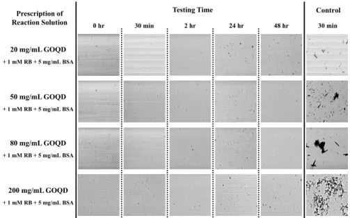
this issue, it has recently been reported that the amino acid structures in BSA can produce a stable aqueous graphene dispersion [32]. Accordingly, BSA was added as the dispersant to provide both hydrophilic and hydrophobic regions on the surface. Finally, four fabrication solutions were prepared, with each containing 5 mg/mL of BSA and 1 mM RB, but incorporating 20, 50, 80, and 200 mg/mL of GODs, respectively. Figure 1 presents images of the fabrication solutions containing 1 mM RB and the various concentrations of GODs (i.e. 20, 50, 80, and 200 mg/mL) both with (the “Testing”) and without (the “Control”) the 5 mg/mL BSA dispersant in deionized water. Images were captured using a CCD to grab 100 × 100 μm2 area images over a 48 hr period). As can be seen in the far right column of Fig. 1,
serious aggregation occurred within just 30 min in the “Control” solutions, which as mentioned contained no BSA. The GODs agglomerated or crystallized via either the van der Waals interactions or the RB, which absorbed photon energy to transform into the triplet state, thereby becoming activated GODs. Moreover, previous research has shown that some chemically converted graphene agglomerates cannot be reversed into their original state [32]. Generally, the TPC fabrication process with normal materials, e.g., monomers and protein molecules, usually requires at least 30 min for a usable microstructure [5,6]. As such, GOD-based multiphoton microfabrication with RB but without a dispersant would not be possible since the solution aggregates within 30 min. However, when the GODs were sonicated with the BSA in solution at 25 °C for 30 min, the resulting dispersion was highly stable in the various fabrication solutions, as shown by the 5 columns of Fig. 1 under “Testing Time”. As the images show, the testing solutions are homogenous and clear after the sequential time-periods of 30 min, 2 hr, 24 hr, and 48 hr with various GOD concentrations ranging from 20, 50, 80, and even 200 mg/mL. These results suggest that the dispersion is due to the electrostatic repulsion of the BSA molecules on graphene, which renders microfabrication for up to 48 hr or longer possible.
Testing Time Prescription of
Reaction Solution 0 hr 30 min 2 hr 24 hr 48 hr 30 min
Control 20 mg/mL GOQD + 1 mM RB + 5 mg/mL BSA 50 mg/mL GOQD + 1 mM RB + 5 mg/mL BSA 80 mg/mL GOQD + 1 mM RB + 5 mg/mL BSA 200 mg/mL GOQD + 1 mM RB + 5 mg/mL BSA
Fig. 1. Bright-field time-lapse images of fabrication solutions with (under different “Testing Time”) and without (under “Control”) the BSA dispersant (at the same concentration, 5mg/mL). The GOD’s concentrations were varied from 20.0 to 200.0 mg/mL (top to bottom). The dispersions of the testing solutions were stable despite increasing concentrations of GODs. 3.2 Surface morphology of fabricated structures at the various concentrations
To fabricate microstructures via TPC from different GOD concentrations with BSA, two separate solutions containing 1 mM photoactivator (RB) with 5 mg/mL dispersant (BSA), and two respective concentrations of GOD, namely 20 mg/mL and 100 mg/mL, were mixed at 25 °C and then sonicated for 10 min. In TPC processing, the crosslinking efficiency is proportional to the TPA of the photoactivator; accordingly, the fabrication-laser wavelength was fixed at around 720 nm for the RB photoactivator, as mentioned above. To better evaluate the BSA-modified GOD microstructures, a pure BSA microstructure containing 50 mg/mL BSA and 5 mM RB was first fabricated. This concentration of RB was chosen due to its higher singlet oxygen quantum yield for implementing protein crosslinking processing. Compared with TPC, which uses a protein as a reactive monomer, we found that the laser power of protein crosslinking processing was higher than that of GOD self-crosslinking processing. In this study, to implement multiphoton fabrication of a 3D-crosslinked pure BSA microstructure, the power of the 100 fs laser at the repetition rate of 80 MHz was initially 26.7 mW; however, for the two GOD fabrication solutions, the laser power reduced to 16.7 mW. This phenomenon might be attributable to the thermal absorption effects of the GODs in the fabrication solution.
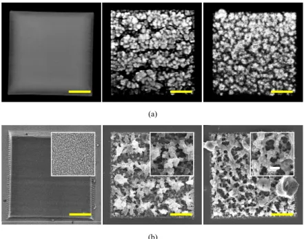
Figure 2 presents a series of images, viewed from left to right, of three fabricated microstructures respectively created from fabrication solutions containing 50 mg/mL BSA, and 20 mg/mL and 100 mg/mL GOD both with 5 mg/mL BSA dispersant. Images in Fig. 2(a) were taken by TPEF microscopy, while those in Fig. 2(b) are via scanning electron microscopy (SEM) (JEOL 7000, Japan). The designed structure is a square with a base area of 40 × 40 μm2 and a thickness of 30 μm, for which the fabrication scan velocity was 20 kHz.
After the TPC process, the microstructure was washed with deionized water to remove any non-crosslinked fabricated solution. The left image of Fig. 2(a) shows that the pure BSA structure is relatively smooth. The microstructures in the middle and right of Figs. 2(a) and 2(b) contain a large proportion of GODs and exhibit a highly porous freestanding structure. The porous morphology may be due to the laser-induced transformation or the π-π staking interactions amongst the GODs [33]. The zoomed-in SEM images in the insets of Fig. 2(b)
reveal the very dissimilar morphologies of these three microstructures. The microstructure fabricated from the 20 mg/mL GOD concentration the middle images of Figs. 2(a) and 2(b)) has relatively deficient GOD self-crosslinked areas and cannot form the porous rings as clearly as the microstructure fabricated with the 100 mg/mL GOD solution (the images on the right of Figs. 2(a) and 2(b)). Moreover, the GOD also can be a fluorescent contrast agent for the visualization of crosslinked microstructures, as shown in the middle and left images of Fig. 2(a). According to our previous study [34], the GODs in the fabricated microstructure can be selectively converted into reduced GO by re-micromachining the desired reduction area at stronger laser power. Consequently, the experimental results demonstrate that microstructures containing high concentrations of GODs can be fabricated over extended periods of time with the use of BSA as a dispersant. Moreover, such microstructures could not only be applied in the biomedical field but also in the 3D-graphene micro-supercapacitor field.
(a)
(b)
Fig. 2. (a) TPEF and (b) SEM images of three different fabricated microstructures from BSA only, 20 mg/mL GOD with 5 mg/mL BSA, and 100 mg/mL GOD with 5 mg/mL BSA (from left to right). The insets in (b) are SEM zoomed-in images with magnifications of 45000X, 12000X, and 12000X (from left to right). Scale bar: 10 μm.
3.3 Cell adhesion on BSA-modified GOD island-bridge structure
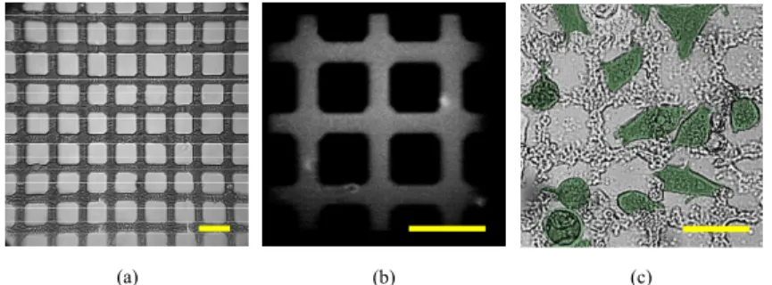
To investigate the biocompatibility of fabricated GOD microstructures, a positive island-bridge pattern was created. Figure 3(a) shows a 2D BSA-modified GOD island-island-bridge pattern for cell proliferation and adhesion while Fig. 3(b) offers the zoomed-in TPEF image. The accessible microstructure has an area of 345 × 345 μm2, with an island diameter of 20 μm and
bridge width of 10 μm. The microstructure was fabricated at a wavelength of 720 nm, the fabrication solution of which consisted of 5.0 mM RB, 100 mg/mL GODs, and 50 mg/mL BSA. Herein, the BSA concentration was increased from 5 to 50 mg/mL to ensure biocompatibility. After the BSA-modified GOD microstructure was fabricated by the laser, the microscope slide was repeatedly washed with deionized water, and then treated with ultraviolet light for 48 hr to photobleach the RB and sterilize for cell culture. The MDA-MB-231 human breast cancer cell line was grown in 90% Dulbecco’s modified Eagle’s medium containing 10% fetal bovine serum (FBS) at 37 °C, 5% CO2/ 95% air, cultured with penicillin,
and then subcultured with trypsin (Gibco-BRL, Gel, USA). To observe the cell behavior in the BSA-modified GOD microstructure, a cell seeding density of 1 × 10⁴ cells/mL was
cultured on the microstructure, after which the slide was incubated for 24 hr. After the 24-hr incubation, most of the MDA-MB-231 cells had attached and were growing on the BSA-modified GOD microstructure. Compared with the island-bridge structure before cell seeding, the structure shown in Fig. 3(c) appears uneven due to the absorption of cell secretions and the extended soaking in Dulbecco’s modified Eagle’s medium before observation. This result implies that the BSA-modified GOD material is a potential candidate for manufacturing homogenous bio-mimetic microstructures and bio-scaffolds that are a challenge to fabricate using GOD-only material.
(b)
(a) (c)
Fig. 3. GOD island-bridge microstructure with an area of 345 × 345 μm2, island diameter of 20
μm and bridge width of 10 μm. (a) Full-view bright-field image, (b) zoomed-in TPEF image, and (c) pseudo-color image with migrated MDA-MB-231 human breast cancer cells on the island-bridge microstructure after 24-hr cell seeding. Scale bar: 50 μm.
3.4 3D BSA-modified GOD microstructures
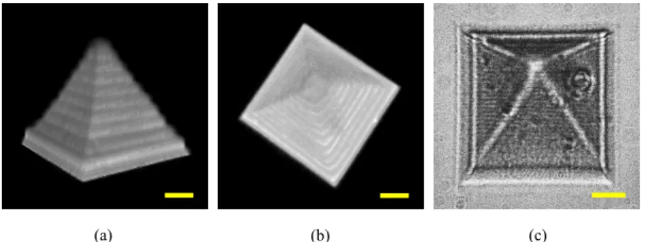
To create 3D freeform microstructures with this microfabrication setup, the sequential 2D bitmap files can be designed with MATLAB or converted from 3D models (DXP format), after which the bitmap files are downloaded into the customized control system, written by LabVIEW, for fabrication. The laser dosage is controlled via the acousto-optic modulator for excitation at the focal point of the objective lens according to the corresponding pixel gray value of the bitmap files. However, achieving a 3D GOD-only microstructure in our previous study was problematic due to the aforementioned aggregation problem [34]. Thus, a pragmatic solution for fabricating freeform 3D GOD microstructures is to adopt more BSA and less GOD. Herein, the BSA concentration was increased to 100 mg/mL, the GODs reduced to 50 mg/mL, and the RB photoactivator held at 2.0 mM. Figures 4(a) and 4(b) show the TPEF images of the fabricated 3D structure from both the side and top views using our lab-made conventional point scanning TPEF microscope. The pyramidal structure, with a base area of around 50 × 50 μm2 and a height of 35 μm, was fabricated via a laser power of 16.7
mW at 720 nm, 20 kHz pixel-scanning rate, and a z-axis step of 1 μm. With the aim of avoiding thermal damage yet maintaining an adequate laser dosage, scanning was performed 5 times per layer at the same depth rather than simply decreasing the pixel-scanning rate. Figure 4(c) shows the bright-field image of the fabricated pyramidal microstructure. The 3D TPEF images were obtained with 1.0 mW at 800 nm and a 30 kHz pixel-scanning rate. Accordingly, this approach using BSA as a dispersant to prevent GOD-aggregation not only extends the fabrication window of GOD microstructures, but also holds the potential to apply such 3D microstructures in various research fields, such as bioelectronics, supercapacitors, and tissue engineering, simply by adjusting the proportion of the GOD and BSA concentrations in the fabrication solution.
(b)
(a) (c)
Fig. 4. Fabricated pyramid after removing the remaining solution: 3D TPEF images of (a) side view and (b) top view, and (c) bright-field image. Scale bar: 10 μm.
4. Conclusions
GOD aqueous solutions with RB as the photoactivator can be used to fabricate 3D freeform GOD microstructures that approach the diffraction limit of the spatial resolution; however, the GODs in the fabrication solution with RB quickly aggregate. To overcome this drawback, BSA was adopted as a dispersant to prevent the GODs self-aggregation via electrostatic repulsion on the GOD surface. In this manner, long-term stable dispersions of GODs in solution can be achieved. Moreover, by adjusting the proportion of GOD and BSA concentrations, diverse applications, such as 3D micro-electronic devices, photonic crystals, and cell guiding in 3D environments can be realized. To demonstrate one application of this fabrication technique, a BSA-modified GOD island-bridge microstructure was successfully created and the adhesion and growth of MDA-MB-231 cells on the structures were analyzed. Accordingly, this approach holds great potential for fabricating complex 3D GOD microstructures featuring the unique properties of graphene.
Funding
Ministry of Science and Technology (MOST) of Taiwan (MOST 104-2221-E-009-203-MY3, MOST 104-2221-E-006-211, MOST 105-2221-E-006-147).