~ ) Pergamon Printed in Great Britain. All rights reserved 0017-9310/95 $9.50+0.00
0017-9310(95)00053--4
Experimental study of the heat transfer
enhancement of an outer tube with an inner-tube
insertion
W U - S H U N G FU, C H I N G - C H I TSENG and C H I H - S H U N G H U A N G Department of Mechanical Engineering, National Chiao Tung University, Hsinchu 300, Taiwan,
Republic of China
(Received 16 March 1994 and in final form 20 January 1995)
Abstract--This experimental study aims to investigate the heat transfer phenomena of an outer tube with an inner-robe insertion. The naphthalene sublimation method is adopted which measures the sublimation depth of naphthalene necessary to reduce the local heat transfer through the analogue relation between heat and mass transfer. The working fluid is air and the data runs are performed for Reynolds numbers of 1058, 13150 and 1965. The comparison between experimental and numerical results shows good agreement. It is also found that, with an inner-tube insertion, the heat transfer rate of the outer tube increases as the Reynolds number of the tube flow and the size of inner tube increase, as long as the inner tube is not larger
than a given size.
INTRODUCTION
Circular tubes are widely employed in heat-exchange equipment, and the problem of how to enhance the heat transfer rate of a circular tube has become a very important subject for research. Different methods have been proposed for this subject, including passive methods that require no external power such as treated surfaces, extended surfaces, swirl flow devices, and active methods that require external power such as surface vibration, fluid vibration, injection and suction. Bergle,; [1, 2] made a detailed survey about this subject. Many related researches are also available
[3-8].
In [9], Fu and Tseng tried to enhance the heat transfer rate of tube flow by inserting a coaxial inner tube into a tube (the outer tube) to deflect the fluid to the hot wall of the outer tube. Since the configuration of the inner tube is very simple, the accompanying pressure drop is not very serious and the results showed that this method does meet the goal of heat transfer enhancement. However, the study was purely a numerical analysis and lacked experimental data to verify its validity. Therefore in this study, further investigation c,f this issue will be carried out by numerical and experimental methods. For the exper- imental part, an inner tube was fixed on the wall of an outer tube by three rear fins. Four different sizes of inner tube and Reynolds numbers of 1058, 1360 and 1965 were used during experimental data runs. Since the diameters of the tube were very small, it was difficult to measure the local heat transfer rate directly through the use of electrical heaters, and thus the naphthalene sublimation method was chosen for the experiment. Tile sublimation depth of naphthalene
was measured for each data run to reduce the local Nusselt number through the analogue relation between heat and mass transfer. In the numerical analysis, in order to simulate the experimental situ- ation more precisely, the method used in Fu and Tseng [9] was modified and the thickness of inner tube and the fins in the rear part of the inner tube were taken into consideration, therefore, the numerical com- putation for both flow and thermal fields became a three-dimensional problem.
The results were found to give good agreement between numerical and experimental analyses. The heat transfer enhancement of tube flow was dependent on both the size of the inner tube and the Reynolds number of the tube flow. In general, the heat transfer of tube flow increases with the increase of Reynolds number and size of inner-tube. However, the inner- tube size should not be greater than a certain limit, otherwise, the heat transfer of the tube will decrease.
PHYSICAL MODEL AND EXPERIMENTAL PROCEDURE
In the numerical study of F u and Tseng [9], the heat transfer phenomena of a constant-wall-temperature tube with an inner-tube insertion were investigated where the thicknesses of inner tube were assumed to be infinitely small and the thermal conductivity of the inner tube was assumed to be much larger than that of the fluid. This numerical model is laminar flow and shown in Fig. 1. When the flow passes the inner tube, the fluid separates and two flow paths are formed, which include the path between the inner and outer tubes and the path inside the inner tube. By changing the size of the inner tube, the friction drags of these 3443
3444 W.-S. FU
et al.
NOMENCLATURE
D diffusivity of the naphthalene in air /'/max [cm 2 s ']
d tube diameter [mm] x
f friction factor
hx local heat-transfer coefficient [W K - J]
hmx
local mass-transfer coefficient [m s-1]k thermal conductivity of fluid a
[ W m - 1 K - ' ] #
l tube length [mm] v
lsb x local depth of the naphthalene p
sublimation [mm] Ps
flow rate [kg s -~] Pvw
Nux
local Nusselt number,h doi/k
Nux
average local Nusselt number Pv~P pressure [Pa]
Pvw pressure of the naphthalene vapor [Pa]
Pr
Prandtl number[v/a]
R universal gas constant [N m k g - J K - i]
r radial coordinate
Re
Reynolds number,p~doJp
Sc
Schmidt number[v/D]
Shx
local Sherwood number,hmxdoi/D
Tw temperature along the wall of outer tube [K]
u velocity in the axial direction [m s -1] t7 average velocity in the axial direction
[ms ']
maximum velocity in the axial direction [m s - q axial coordinate. Greek symbols thermal diffusivity [m 2 s-l] dynamic viscosity [kg m-~ s 1] kinematic viscosity [m 2 s-~] density of fluid [kg m-3]
density of naphthalene solid [kg m - 3] local density of naphthalene vapor [kg m -3]
density of naphthalene vapor in the mainstream [kg m-3].
Subscripts
ii inner radius of the inner tube io outer radius of the inner tube m mass transfer
oi inner radius of the outer tube oo outer radius of the outer tube.
Superscript
- average value.
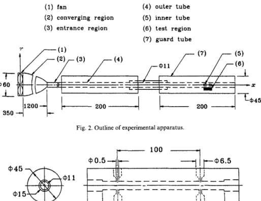
paths are varied, which causes the flow rate for each path to be changed. It is shown that the heat transfer augmentation is reached in the heated region as more fluid is led to the path between the inner and outer tubes. The experimental apparatus of this study is set up according to the numerical model, and is shown in Fig. 2. A blower (1) with a small flow rate (& = 0.08 m 3 m i n - l) is installed to control the flow rate of the working fluid and a transistor inverter is used to adjust
the rotating speed of this blower. The convergent sec- tion (2) is followed by the entrance region (3). The length of the entrance region is 1200 mm
(13/doi
~ 110), which is long enough to make the flow of the fluid fully developed as the fluid enters the test section (4). The test section, which is the outer tube, includes two regions, one being the pressure-drop region in the front part (shown in Fig. 3) which is designed to measure the pressure drop of the tube flow(1) o u t e r t u b e
(2) i n n e r t u b e
A A A/
i n s u l a t e d h e a t t r a n s f e r reglon r e g i o n(I) fan
(4) outer tube
(2) converging region
(5) inner tube
(3) entrance region
(6) test region
(7) guard tube
I, /.,
(I)
/ - -
(7) / - - (5)
o,,
/ / -
4"--/--
J
.
-i--lz6°-'3 o
-..
_
zoo
I
zoo
-,
- E , 4 5
Fig. 2. Outline of experimental apparatus.
~i
~6.5
~b4'* ~ x ~ ~"-" ~ ' + ' ~ ! I ' ,
~ l l
'
' " 1 ~ - J - -
- - - - ' -
Fig. 3. Pressure-drop region.
to ascertain the Reynolds number of the tube flow, the other being the casting naphthalene region (shown in Fig. 4) where the mass transfer rate of naphthalene is measured to reduce the local heat transfer rate. The stainless-steel mould for producing the naphthalene coating has the same arc shape as the inside wall of the outer tube (Fig. 4). The roughness e of the surface of the stainless-,;teel mould is less than 3 x 10 -3 mm
(~/do~
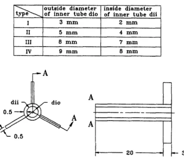
~ 3 × 10 4). The final assembly of the casted naphthalene region is shown in Fig. 5. The assump- tions of infinitely small tube wall thickness and high thermal conductivity of inner tube are as made in F u and Tseng [9], the inner tube (including the rear fins to fix the inner tube, Fig. 6) is made of pure gold with thickness of 0.5 mm. Fins are placed at the rear part of the inner tube to lessen the influence on the flowfield of the test section. F o u r different sizes of inner tube for the data runs are also shown in Fig. 6.
The naphthalene sublimation method is adopted to measure the local sublimation depth of naphthalene, which is used to calculate the mass transfer rate of naphthalene, then the local heat transfer rate is derived through the well-established relation between mass and heat transfer,
Nux/Shx = (Pr/Sc) n,
where the value of n is dependent on the flow characteristic and is suggested in [10-16]. In this study, n = ~ is chosen which is widely used for the measurement of local heat transfer rate [10-16].Each experimental data run includes two measure- ments and a brief outline is given as follows.
(1)
The measurement of Reynolds number of the tube
flow.
The Reynolds number of the tube flow can be:casting naphthalene
1_7
6 0
3 o - 4 - 20 J
I- 2 0 i~
3 r a m f e e d i n g h o l e ¢ 1.5rnm h o l e f o r t h e r m o e u p l e Fig. 4. Casting naphthalene region.3446 W.-S. FU et al.
(I) casting n a p h t h a l e n e region
( 2 )
inner tube
- -'= 60 ~'//?7/J~'f/?'/A(2)
60 -Fig. 5. Assembly of the casting naphthalene region.
1
(1)
u n i t : r a m
obtained by two methods. One is to employ a Pitot tube directly to measure the fluid velocities for 21 points across the tube to attain the velocity profile of the tube flow under the fully developed condition. As shown in Fig. 7, the velocity profiles measured by the Pitot tube shows excellent agreement with the ana- lytical expression for fully developed flow. Then, the average fluid velocity is obtained by a Simpson's rule integration of the velocity profile ; this quantity is thus used in the computation and the Reynolds number of the tube flow (Appendix 1, equation (A1)) can be obtained successively. The other is to measure the pressure drop (Appendix 1, equation (A2)) as the fluid of fully developed flow passes the pressure-drop region (100 mm in length). The average velocity of the tube flow can then be calculated with the aid of the friction factorf(equation (A3)), and the Reynolds
number of the tube flow (equation (A4)) can be obtained. The values of Reynolds number obtained from the above two methods are shown in Appendix 1. The deviation of these Reynolds numbers are within 1.5%. The Reynolds number of the tube flow for each experimental data run is calculated by the latter method (equations (A2), (A3) and (A4)), which is accurate and convenient.
(2) The measurement for sublimation depth of naph- thalene. The procedures are primarily according to the methods of [10-16]. The sublimation depth of naphthalene caused by natural convection is estimated at first. Molten naphthalene is poured into the mould. After the naphthalene solidifies, the thickness of the naphthalene coating layer measured by an ultra-pre- cision depth gauge (the resolution is 1/~m) is recorded. Then the naphthalene coating layer is put into the
I
II
Ill
IV
outside d i a m e t e r inside diameter of inner tube dio of inner tube dii
3 m m 2 m m 5 m m 4 m m 8 m m 7 m m 9 m m 8 m m d i i ~ dio
0 . ~ ~
A
A
2 0 ~E
~
x
' U ~
-8- 5 . 5 . . . . 3 . 5 ~ 2 . 5 ~ 0.5 o,O,A:experimental data -0.,5 - - - :numerical result ~ - 1 . 5 - 2 . 5 - 3 . 5 - 4 . 5 - 5 . 5 / ' ' ' ' 0.0 0.2 0.4 0.6 0.8 1.0u (u/u=.~)
Fig. 7. Velocity ]profile at exit of pressure-drop region.
laboratory to evaluate the sublimation due to natural convection. The thickness of the naphthalene is mea- sured at grid points spaced at 0.025 cm interval (total 80 points). Measurements are taken each hour with each set of measurements taking 6-8 minutes. After several repetitions of the above measurements, the sublimation by natural convection is estimated to be at about 3 #m h-~. Next, the coating layer of naph- thalene is installed on the test section and the blower is started. The Reynolds number of the tube flow is adjusted in accordance with the pressure drop of the test section as described earlier. The duration of each data run is about 2h and the change of the mean thickness of naphthalene during the course of the experiment is about 40 /~m. Then the naphthalene coating is removed from the test section to the plat- form of the depth gauge to measure the local sub- limation depth of naphthalene. The sublimation depth due to natural convection is subtracted, and these values are substituted into the analogue relation between mass and heat transfer (equations (1)-(4)) to get the local Nusselt number Nux distribution.
The local depth/sbx of the naphthalene sublimation distributions for Re = 1360 is shown in Appendix 2.
Nux/Shx = (Pr/Sc)" (1) Nu~ = h~do,/k (2) Shx = hmxdoi/D (3) hmx -= lsb x X Ps/(Pvw - - P ~ ) (4) 1 f 19"75(mm) - - - Nux d x Nux 19.5(mm) d0.25(mm) p~= 1 1 4 5 k g m -3 (293K) from [17] Pvw = Pvw/RTw log (Pvw/133.3) = 12.8612-4577.47/ (Tw+30.544) from [181 R = 6 4 . 8 6 7 N m k g - l K i D = 0 . 0 6 8 8 5 c m 2s 1 (293K) Pr = 0.71(293 K) from [19] S c = v/D = 2.152(293 K).
Since the laboratory is far larger than the exper- iment setup, the ambient naphthalene vapour density is negligible. The temperature used to decide the properties of naphthalene and the working fluid is measured by a thermocouple set 0.5 mm beneath the surface of the naphthalene coating layer. The relative uncertainty proposed by Kline [20] is used to analyse the results and the uncertainties for Nusselt and Reyn- olds numbers are about 5.5% and 1.31% respectively.
RESULTS AND DISCUSSION
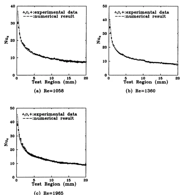
The working fluid is air, the temperature of which is conditioned at about 20°C. For validating the accu- racy and availability of the experimental apparatus, the local Nusselt number Nux distributions without inserting an inner tube along the outer-tube wall are first examined. The results shown in Fig. 8 are for the situations of Reynolds numbers of 1058, 1360 and 1965 respectively. The experimental results of three data runs are indicated in each situation, and those data for which the reproducibility is acceptable are in good agreement with the numerical results (dashed lines). The local Nusselt number decreases when the length of the test regions increases. To save time, two experimental data runs are conducted for each latter situation.
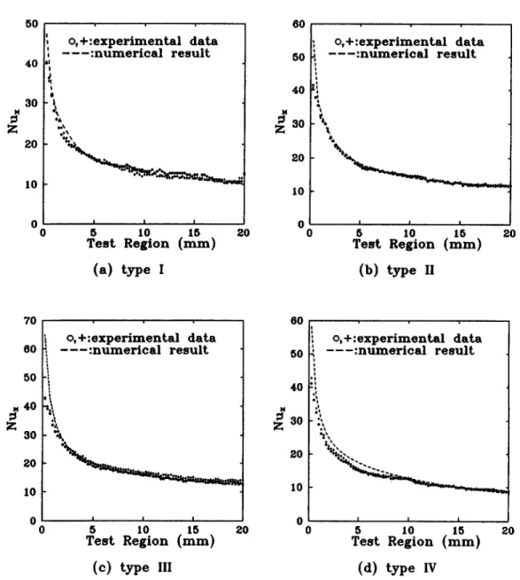
In Fig. 9, for Re = 1058, the consistency of the results obtained from the experimental and numerical methods is good for type-II and type-Ill cases, but slightly deviates for type-I and type-IV cases. When the inner tube is smaller (type I), the path inside the inner tube is narrow, which is apt to cause the fluid to flow through the path during the experimental data run, which makes the numerical calculation process different. It is suggested that the slight deviation of the results of the type-I case is caused by the above- mentioned factors. The largest deviation is about 3% as indicated in Table 1. In Fig. 10, for Re = 1360, the phenomena are similar to those shown in Fig. 9. The difference between the results of experiment and numerical calculation for the type-IV case is more remarkable than those of the other types. As the inner tube is larger (type IV), the path between the inner and outer tubes becomes narrow, which causes the phenomena to be similar to those mentioned above. The largest deviation is about 10%, as indicated in Table 1. The phenomena shown in Fig, 11 for R e = 1965 are like those shown in Figs. 9 and 10, the largest deviation still occurs for the type-IV case.
3448 W.-S. FU et al. 40 30
•a•
20 10 0 o A , o , + : e x p e r i m e n t a l d a t a - - - : n u m e r i c a l r e s u l t'
'
'5
5 10 1 T e s t R e g i o n ( r a m )( a )
Re=1058
20 50 40 30 20 10 0 0 ~ , o , + : e x p e r i m e n t a l d a t a - - - : n u m e r i c a l r e s u l t I I I 5 10 15 20 T e s t R e g i o n ( r a m ) ( b ) R e = 1 3 6 0 50 40 30 20 10 ~ , o , + : e x p e r i m e n t a l d a t a - - - : n u m e r i c a l r e s u l t t i I i 5 10 15 20Test Region (ram)
(c) Re=1965
50
40
8O
20
10
00
o, ÷ : e x p e r i m e n t a l
d a t a
. . . . : n u m e r i c a l r e s u l t
p I I I 5 1015
T e s t R e g i o n ( r a m )
( a ) t y p e I
20
6 0 5 0 4 0 3 o2O
10
00
o , + : e x p e r i m e n t a l
d a t a
- - - : n u m e r i c a l
r e s u l t
5
10
mlSm
20
T e s t R e g i o n (
)
( b ) t y p e II
6 050
40
3O
Z
2o
10O
0
o , + : e x p e r i m e n t a l
d a t a
. . . . : n u m e r i c a l r e s u l t
I I I 510
15
T e s t R e g i o n ( m m )
( c ) t y p e Ill
6 0 5 040
2o
10 20o , + : e x p e r i m e n t a l
d a t a
- - - : n u m e r i c a l
r e s u l t
\
I I I5
10
15
T e s t R e g i o n ( m m )
( d ) t y p e IV
Fig. 9. Local Nusselt number distribution for
Re= 1058.
3450
W.-S,
F U e t al.Z
50
40
o, + : e x p e r i m e n t a l d a t a
- - - : n u m e r i c a l
r e s u l t
tao
~,
eA 20*a,
10
N I I i0
5
10
15
20
T e s t R e g i o n ( r a m )
( a ) t y p e I
6050
40
~N30
2O
10
00
o , + : e x p e r i m e n t a l d a t a
- - - : n u m e r i c a l
r e s u l t
5 10 1520
T e s t R e g i o n ( m m )
( b ) t y p e II
70
6050
~ 4o
Z
3O
ZO
10
00
o, + : e x p e r i m e n t a l d a t a
- - - : n u m e r i c a l
r e s u l t
5 10 15 ZOT e s t R e g i o n ( m m )
60 50 40~ 3 0
o , + : e x p e r i m e n t a l d a t a
- - - : n u m e r i c a l
r e s u l t
og~~0
10
0 0( c ) t y p e llI
Fig. l 0. Local Nusselt number distribution for
Re= 1360.
I ! I
5 10 15
T e s t R e g i o n ( m m )
( d ) t y p e IV
6O
5O
4O
3O
2O
10
0
0
o , + : e x p e r i m e n t a l
d a t a
. . . .: n u m e r i c a l r e s u l t
I I I5
10
15
T e s t R e g i o n ( r a m )
( a ) t y p e I
70
60
50
4O
Z
30
gO10
02O
0
o,+ : e x p e r i m e n t a l
d a t a
- - - : n u m e r i c a l
r e s u l t
k
I I ! 6 1oT e s t R e g i o n
( b ) t y p e II
20 8070
60
50
~ 4 0
30
20
lO
oo
o , + : e x p e r i m e n t a l
d a t a
i . . . . : n u m e r i c a l r e s u l t
L I i I5
10
15
T e s t R e g i o n ( r a m )
( e ) t y p e Ill
20 807O
6O
5O
Hi,
3o ' : 20 10 0o , + : e x p e r i m e n t a l
d a t a
- - - : n u m e r i c a l
r e s u l t
5
10
15
20
T e s t R e g i o n ( m m )
( d ) t y p e IV
Fig. 11. Local Nusselt number distribution for
Re= 1965.
3452 W.-S. F U et al.
Table 1. The deviation between the experimental and numerical results Average Nusselt number Nux
Experimental Numerical Deviation (%)
Re no. Type results (A) results (B) I(A - B)/BI
empty 11.868 11.541 2.84 I 13.659 13.256 3.04 1058 II 15.267 15.081 1.24 III 16.629 16.194 2.69 IV 12.577 12.879 2.35 empty 12.009 12.221 1.73 I 15.035 15.298 1.72 1036 II 16.568 16.866 1.77 III 18.371 17.494 5.01 IV 13.768 15.229 9.59 empty 13.966 13.686 2.05 I 16.639 16.314 1.99 1965 II 19.021 18.672 1.87 III 20.321 20.784 2.23 IV 17.569 18.791 6.51
Generally, the m u t u a l i n t e r a c t i o n between the iner- tia a n d viscous forces affects the flow o f fluid, a n d the flow field varies w h e n the R e y n o l d s n u m b e r o f the t u b e flow c h a n g e s [9]. As a result, s h o w n in T a b l e 1, for R e y n o l d s n u m b e r s o f 1058 a n d 1360, the average N u s s e l t n u m b e r s o f type I are larger t h a n those o f type IV. Conversely, for R e y n o l d s n u m b e r o f 1965, the average Nusselt n u m b e r o f type IV is larger t h a n t h a t o f type I.
CONCLUSIONS
This e x p e r i m e n t a l s t u d y employs the n a p h t h a l e n e s u b l i m a t i o n m e t h o d to investigate the h e a t t r a n s f e r p h e n o m e n a o f a n o u t e r t u b e w i t h a n i n n e r - t u b e inser- tion. F o u r different sizes o f i n n e r t u b e a n d R e y n o l d s n u m b e r s o f 1058, 1360 a n d 1965 are c o n s i d e r e d a n d the conclusions are s u m m a r i z e d as follows.
(1) G o o d a g r e e m e n t is f o u n d b e t w e e n the n u m e r i c a l a n d e x p e r i m e n t a l results.
(2) O w i n g to the i n s e r t i o n o f the i n n e r tube, the flow rate between the walls o f the i n n e r a n d o u t e r tubes varies, which affects the h e a t t r a n s f e r rate. T h e h e a t t r a n s f e r rate with a n i n n e r - t u b e i n s e r t i o n increases with the size o f the i n n e r tube, b u t the i n n e r - t u b e size s h o u l d n o t be b e y o n d a certain limit, otherwise the h e a t t r a n s f e r o f the o u t e r tube will decrease.
(3) T h e R e y n o l d s n u m b e r also influences the flow rate v a r i a t i o n between the walls o f the i n n e r a n d o u t e r tubes which results in different h e a t t r a n s f e r per- formance. As the R e y n o l d s n u m b e r o f the tube flow increases, the h e a t t r a n s f e r rate also increases.
Acknowledgment--The support of this work by National Science Council, Taiwan, R.O.C. under contract NSC 82- 0401-E-009-389 is gratefully acknowledged.
REFERENCES
1. A. E. Bergles, Recent development in convective heat- transfer augmentation, Appl. Mech. Rev. 26, 675~582 (1973).
2. A. E. Bergles, Survey and evaluation of techniques to augment convective heat and mass transfer, Prog. Heat Mass Transfer 1, 331-424, Pergamon Press, Oxford (1969).
3. D.A. van Meel, A method for the determination of local convective heat transfer from a cylinder placed normal to an air stream, Int. J. Heat Mass Transfer 5, 715-722 (1962).
4. S. V. Patankar, M. Ivanovic and E. M. Sparrow, Analy- sis of turbulent flow and heat transfer in internally finned tubes and annuli, A S M E J. Heat Transfer 101, 29 37 (1979).
5. G. J. Rowley and S. V. Patankar, Analysis of laminar flow and heat transfer in tubes with internal cir- cumferential fins, Int. J. Heat Mass Transfer 27, 553 560 (1984).
6. E. M. Sparrow and A. T. Prata, Numerical solutions for laminar flow and heat transfer in a periodically con- vergent-divergent tube with experimental confirmation,
Numer. Heat Transfer 6, 441-461 (1983).
7. A. T. Prata and E. M. Sparrow, Heat transfer and fluid flow characteristics for an annulus of periodically vary- ing cross section, Numer. Heat Transfer 7, 285-304 (1984).
8. A. K. Agrawal and S. Sengupta, Laminar flow and heat transfer in blocked annuli, Numer. Heat Transfer 15, 489-508 (1989).
9. W. S. Fu and C. C. Tseng, Enhancement of heat transfer for a tube with an inner tube insertion, Int. J. Heat Mass Transfer (in press).
10. E. M. Sparrow and C. H. Liu, Heat-transfer, pressure- drop and performance relationships for in-line, stag- gered, and continuous plate heat exchangers, Int. J. Heat Mass Transfer 22, 1613-1625 (1979).
11. E. M. Sparrow and K. P. Wachtler, Transfer coefficients on the surfaces of a transverse plate situated in a duct flow, Int. J. Heat Transfer 21, 761-767 (1978). 12. E. M. Sparrow, M. Molki and S. R. Chastain, Turbulent
heat transfer coefficients and fluid flow pattern on the forces of a centrally positioned blockage in a duct, Int. J. Heat Mass Transfer 24, 507-519 (1981).
pressure drop for a staggered wall-attached array of cylinders with t!ip clearance, Int. J. Heat Mass Transfer 21, 1369-1378 (1978).
14. E. M. Sparrow, J. E. Niethammer and A. Chaboki, Heat transfer and pressure drop characteristics of array of rectangular modules encountered in electronic equipment, Int J. Heat Mass Transfer 25, 961-973
(1982).
15. R. J. Goldstein, The effect of a wall boundary layer on local mass transfer from a cylinder in cross flow, J. Heat Transfer 106, 260-267 (1984).
16. R.J. Goldstein, S. Y. Yoo and M. K. Chung, Convective
mass transfer from a square cylinder and its base plate, Int. J. Heat Mass Transfer 33, 9-18 (1990).
17. John A. Dean, Lange's Handbook o f Chemistry (7th Edn). McGraw-Hill, New York (1973).
18. Robert C. Weast, CRC Handbook o f Chemistry and Physics (67th Edition). Chemical Rubber, Cleveland, OH (1986).
19. Ping-Hei Chen and Pau-Hwa Wung, Diffusion coefficient of naphthalene in air, J. Ch. I. Ch. E21, 161- 166 (1990).
20. S. J. Kline, The purpose of uncertainty analysis, A S M E J. Fluids Engng 117, 153-160 (1985).
APPENDIX
TabLe A1. The measurement of the Reynolds number (padod#) of the tube flow (for air, 293 K)
Runs Integrate the velocities of the fluid at 21 points measured by pitot-tube with Simpson integrate method to obtain the average velocity a (m s ~) of the tube flow
Use a to calculate the Reynolds number (padoi/#) of the tube flow (equation (A1))
2.669 1.828 1.541 1957 1340 1130 Runs The pressure drop (Ah) in Utilize Ah to calculate
the pressure-drop region the average velocity a (100 mm in length) (m s -~) of the tube flow (equation (A2)) (equation (A3))
Use to calculate the Reynolds number (pado~/#) of the tube flow (equation (A4))
The deviation between the Reynolds number (A1) and (A4) = [(A1)- (A4)]/(AI) 1 0.26 2.679 1965 0.37% 2 0.18 1.855 1360 1.49% 3 0.15 1.546 1138 0.71% Re = Pairl2doi/llair AP = pH2ogAh Ah = m m - H 2 0 AP = fn(l/do0 f = 64~Re AP 64 1 P,2ogAh ,Uair l - - - - 64 _ ~
Pair/~ 2 Re doi Pair ~2 Pairudoi a2 = 10.304Ah Re = Pairfldoi/~air .
(AI)
(A2)
(A3) (A4)3454 W.-S. FU et al. v 100 9 0 8 0 70 60 50 40 30 20 I0 0 o , + : e x p e r i m e n t a l d a t a % T e s t R e g i o n ( r a m ) 10 O0 90 6 0 70 60 50 40 30 20 10 0 o , + : e x p e r i m e n t a l d a t a - o
-;.
;
1'0
I;
2o
T e s t R e g i o n ( r a m ) ( a ) t y p e I ( b ) t y p e II 110 lOO 9 0 ~ " 8 0 ~ 70 ~ 6 0 10o 90 o , + : e x p e r i m e n t a l d a t a o,+:experimental data 80 o ~* 6o ¢ 50 * 50 - 4 0 ao ".~.. 30~.
O0 5 10 15 20 O0 5 10 15 ZOTest Region ( r a m ) Test Region ( m m ) ( c ) t y p e IIl ( d ) t y p e IV
![Fig. 1. Physical model for the numerical study in Fu and Tseng [9].](https://thumb-ap.123doks.com/thumbv2/9libinfo/7619621.131555/2.789.85.707.72.573/fig-physical-model-numerical-study-fu-tseng.webp)
![Fig. 7. Velocity ]profile at exit of pressure-drop region.](https://thumb-ap.123doks.com/thumbv2/9libinfo/7619621.131555/5.789.95.359.76.399/fig-velocity-profile-exit-pressure-drop-region.webp)