Research Article
Broadband Loop Antenna on Soft Contact Lens for
Wireless Ocular Physiological Monitoring
Ssu-Han Ting,
1Bo-Ming Jeng,
1Wen-Shan Chen,
2Jin-Chern Chiou,
3and Ching-Hsing Luo
1,41Department of Electrical Engineering, National Cheng Kung University, Tainan City 701, Taiwan
2Department of Electronic Engineering, Southern Taiwan University of Science and Technology, Tainan City 71005, Taiwan 3Department of Electronic and Computer Engineering, National Chiao Tung University, Hsinchu 30010, Taiwan
4Institute of Medical Science and Technology, National Sun Yat-sen University, Kaohsiung, 804, Taiwan
Correspondence should be addressed to Ching-Hsing Luo; [email protected]
Received 28 September 2013; Revised 9 March 2014; Accepted 9 March 2014; Published 13 April 2014 Academic Editor: Zhongxiang Shen
Copyright © 2014 Ssu-Han Ting et al. This is an open access article distributed under the Creative Commons Attribution License, which permits unrestricted use, distribution, and reproduction in any medium, provided the original work is properly cited. This paper presents a novel loop antenna with broadband for wireless ocular physiological monitoring (WOPM). The antenna is fabricated on a thin-film poly-para-xylylene C (parylene C) substrate with a small thickness of 11𝜇m and dimension of 𝜋 × 6.5 × 6.5 mm2. With the advantage of small size, the proposed antenna is suitable to apply to the soft contact lens and transmit the signal
in microelectromechanical Systems (MEMS). Because the pig’s eye and human’s eye have similar parameters of conductivity and permittivity, the experimental results are obtained by applying the proposed antenna on the pig’s eye and cover from 1.54 to 6 GHz for ISM band (2.4 and 5.8 GHz) applications. The measured antenna radiation patterns, antenna gains, and radiation efficiency will be demonstrated in this paper, which are suitable for application of wireless ocular physiological monitoring.
1. Introduction
Recently, monitoring various physiological parameters with biological telemetry system has become an important research topic in wireless monitoring control. To accomplish the wireless monitoring control, the antennas implanted in human body are used to establish communication links between medical sensing devices and external instruments for short-distance biotelemetry. Eye ball monitoring system that is an application of biological telemetry system has also been studied recently, such as monitoring intraocular
pressure monitoring systems [1,2], wireless powered
micro-LED display systems [3], and glucose-monitoring systems [4].
This biotelemetry system can transfer the physiological data into signal and transmit the signal to the external receiving instrument through the antenna on the contact lens. These instruments can share valuable data through the telephone system or the Internet. Through the wireless instruments, the detected physiological data can be sent regularly to the medical institution. An antenna is a key component in
the biotelemetry medical systems to transfer available data. However, the antennas used in human body are difficult to accomplish for interference and size limits. This paper presents a novel loop antenna design for WOPM applications.
2. Antenna Design
2.1. Antenna Geometry. Using the Ansoft simulation soft-ware high-frequency structure simulator (HFSSTM), a novel broadband antenna was designed for the biotelemetry appli-cations (ISM band 2.4 and 5.8 GHz). The geometry of the
proposed antenna shown inFigure 1(a)is fabricated on the
parylene C substrate with thickness of 11𝜇m and permittivity
of 4.Figure 1(b)shows the photograph of proposed antenna
with minicable. The proposed antenna is connected on a soft contact lens with conductive epoxy glue. The overall
dimension of loop antenna is𝜋 × 6.5 × 6.5 mm2with width
of the 1 mm (W1). The parameters of the antenna are listed in Table 1.
Volume 2014, Article ID 952746, 7 pages http://dx.doi.org/10.1155/2014/952746
R1 R2
W1
So contact lens
W2 L1 Feed Ground Z Y X Parylene C Au/Ti Au/Ti H2
So contact lens
H1 H3 W3 (a) Feed Ground Minicable Antenna (b)
Figure 1: Geometry of the proposed antenna. (a) Substrate model. (b) Photograph of a fabricated antenna with minicable.
Table 1: Parameters of the proposed antenna.
Parameter Unit (mm) Parameter Unit (um)
𝑊1 1 𝐻1 100 𝑊2 1.4 𝐻2 0.38 𝑊3 7 𝐻3 11 𝑅1 6.5 𝑅2 5.5 𝐿1 1.3
2.2. Comparison of Permittivity and Conductivity between Human’s and Pig’s Eye. In experimental operation, pig’s eye must be used to replace human’s eye. Therefore, the
param-eters of their tissue must be verified and studied.Figure 2
presents the measurement environment of the minced pig’s eye tissue on an Agilent 85070E dielectric probe kit and
an 8753E network analyzer.Figure 3shows the comparison
results of permittivity and conductivity against frequency between the test tissue (pig’s eye) and the reference tissue
(human’s eye) [5]. The results indicate that the characteristics
of pig’s eye are similar to human’s eye and can be used to replace human’s eye.
3. Results and Discussion
The simulated results of the proposed antenna are obtained
by high frequency structure simulator (HFSS) [6] and
Figure 2: Minced pig’s eye tissue measurement environment.
the measured results are achieved from Agilent E5071C
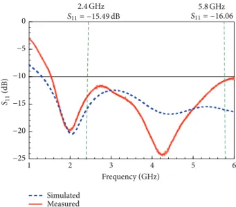
network analyzer. InFigure 4, the measured and simulated
antenna reflection coefficient (S11) of the proposed antenna
demonstrates good agreement. Two resonant modes cre-ate wide operation bandwidth that can also be observed.
The measured S11 based on −10 dB standard achieves an
impedance bandwidth of 4.46 GHz (from 1.54 to 6 GHz) for
ISM application band.Figure 5 shows the simulated input
impedance (imaginary and real parts) for the proposed antenna. From 1.75 to 6 GHz, the input impedance presents
70 65 60 55 50 45 40 1 2 3 4 5 6 10 8 6 4 2 0 Frequency (GHz) Pe rm it ti vi ty C o nd uc ti vi ty (S/m)
Pig’s eye tissue Human’s eye tissue
Figure 3: Comparing the permittivity and conductivity against frequency of the test tissue (pig’s eye) and the reference tissue (human’s eye).
1 2 3 4 5 6 Frequency (GHz) −25 −20 −15 −10 −5 0 Simulated Measured S11 (dB) 2.4 GHz S11= −15.49 dB S115.8 GHz= −16.06
Figure 4: Simulated and measured return loss of the proposed antenna.
1 2 3 4 5 6 Frequency (GHz) −100 −80 −60 −40 −20 0 20 40 60 80 100 In p u t im p eda nce (o hm) Real part Imaginary part 50 −50 2.4 GHz Impedance= 54 + j10 5.8 GHz Impedance= 60 −j3
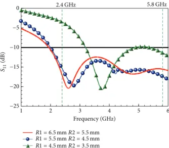
1 2 3 4 5 6 Frequency (GHz) −25 −20 −15 −10 −5 0 2.4 GHz 5.8 GHz R1 = 6.5mm R2 = 5.5 mm R1 = 5.5 mm R2 = 4.5 mm R1 = 4.5 mm R2 = 3.5 mm S11 (dB)
Figure 6: Simulated S11for different loop sizes of the proposed antenna.
1.0000e + 002 9.3789e + 001 8.7577e + 001 8.1366e + 001 7.5155e + 001 6.8944e + 001 6.2732e + 001 5.6521e + 001 5.0310e + 001 4.4099e + 001 3.7887e + 001 3.1676e + 001 2.5465e + 001 1.9254e + 001 1.3042e + 001 6.8310e + 000 6.1971e − 001 Jsurf (A/m) (a) 5.0000e + 001 4.6879e + 001 4.3758e + 001 4.0638e + 001 3.7517e + 001 3.4396e + 001 3.1275e + 001 2.8155e + 001 2.5034e + 001 2.1913e + 001 1.8792e + 001 1.5672e + 001 1.2551e + 001 9.4300e + 000 6.3092e + 000 3.1884e + 000 6.7656e − 002 Jsurf (A/m) (b)
0 45 90 135 180 225 270 315 0 45 90 135 180 225 270 315 0 45 90 135 180 225 270 315 Co-pol
Cro-pol Co-polCro-pol
Co-pol Cro-pol
Y-Z plane X-Y plane X-Z plane
−20 −20 −30 −30 −40 −40 −50 −50 −60 −60 −70 −20 −20 −30 −30 −40 −40 −50 −50 −60 −60 −70 −20 −20 −30 −30 −40 −40 −50 −50 −60 −60 −70 (a) 0 45 90 135 180 225 270 315 0 45 90 135 180 225 270 315 0 45 90 135 180 225 270 315 −20 −20 −30 −30 −40 −40 −50 −50 −60 −60 −70 −20 −20 −30 −30 −40 −40 −50 −50 −60 −60 −70 −20 −20 −30 −30 −40 −40 −50 −50 −60 −60 −70 Co-pol Cro-pol Y-Z plane Co-pol Cro-pol X-Z plane Co-pol Cro-pol X-Y plane (b)
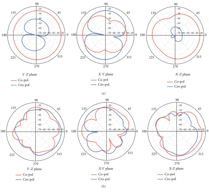
Figure 8: Measured 2D radiation pattern of the proposed antenna: (a) 2.4 GHz; (b) 5.8 GHz.
2.3 2.35 2.4 2.45 2.5 Frequency (GHz) −2 −1 0 1 2 An tenna ga in (dB i) 0 1 2 3 4 5 6 7 8 9 10 R adia tio n efficienc y (%) Antenna gain Radiation efficiency (a) 5.7 5.75 5.8 5.85 5.9 Frequency (GHz) −2 −1 0 1 2 An tenna ga in (dB i) 0 1 2 3 4 5 6 7 8 9 10 R adia tio n efficienc y (%) Antenna gain Radiation efficiency (b)
−30 −20 −10 0 10 20 −30 −20 −10 0 10 20 0 20 40 60 80 100 0 20 40 60 80 100 10 g a vera ge d SAR (W/kg) 8.75E + 01+ 7.95E + 01 to 8.75E + 01 7.16E + 01 to 7.95E + 01 6.36E + 01 to 7.16E + 01 5.57E + 01 to 6.36E + 01 4.77E + 01 to 5.57E + 01 3.98E + 01 to 4.77E + 01 3.18E + 01 to 3.98E + 01 2.39E + 01 to 3.18E + 01 1.59E + 01 to 2.39E + 01 7.95E + 00 to 1.59E + 01 0.00E + 00 to 7.95E + 00 Z (mm) X (mm) (a) −30 −20 −10 0 10 20 Z (mm) −30 −20 −10 0 10 20 X (mm) 0 20 40 60 80 100 0 20 40 60 80 100 10 g a vera ge d SAR (W/kg) 1.01E + 02+ 9.21E + 01 to 1.01E + 02 7.37E + 01 to 8.29E + 01 8.29E + 01 to 9.21E + 01 6.45E + 01 to 7.37E + 01 5.53E + 01 to 6.45E + 01 4.61E + 01 to 5.53E + 01 3.68E + 01 to 4.61E + 01 2.76E + 01 to 3.68E + 01 1.84E + 01 to 2.76E + 01 9.21E + 00 to 1.84E + 01 0.00E + 00 to 9.21E + 00 (b)
Figure 10: Simulated 10 g averaged SAR of the proposed antenna: (a) 2.4 GHz; (b) 5.8 GHz.
small variations and close to 50 Ω impedance matching.
The property of small impedance variations also creates broadband characteristic and covers 2.4 and 5.8 GHz for ISM
band. Figure 6 shows the simulated S11 for different loop
sizes of the proposed antenna. From the simulated results, smaller loop excites higher resonant modes, which meet the theory of resonance. Another feature of the proposed design
is that the resonant modes are tunable.Figure 7shows the
surface current distributions of the proposed antenna at 2.4
and 5.8 GHz. InFigure 7(a), two zeroes and three poles on the
loop form a1 𝜆 resonance. At the higher mode (Figure 7(b)),
five zeroes and four poles create a1.5 𝜆 resonance. To sum
up, the proposed design excites two resonant modes to obtain
broad operation for ISM band that are verified. Figures8(a)
and8(b)present the measured antenna 2D radiation pattern.
In Y-Z plane, the pattern shows near omnidirectional pattern at 2.4 GHz. At higher band at 5.8 GHz, the patterns are twist
and have more zeros.Figure 9shows the measured antenna
radiation gain and efficiency. At 2.4 and 5.8 GHz, the antenna gains are stable and close to 0 dBi. Besides, the radiation efficiency is also stable and close to 1% at that band. Because the human body is a lossy dielectric material, the efficiency
of the antenna is always small [7]. In Figures10(a)and10(b),
the simulated 10 g averaged SAR distributions at ISM band (2.4 and 5.8 GHz) are obtained from the proposed antenna attached on eye tissue.
4. Conclusions
This work presents a novel broadband loop antenna design (optimized bandwidth of 4.46 GHz) for wireless ocular physiological monitoring applications at ISM band (2.4 and 5.8 GHz). The proposed antenna has advantages of simple geometry and easy fabrication. Another feature of this design is that the resonant modes can be changed by varying the loop size. The simulated and measured results are also suitable for wireless ocular physiological monitoring applications.
Conflict of Interests
The authors declare that there is no conflict of interests regarding the publication of this paper.
Acknowledgment
The authors would like to thank the National Science Council in Taiwan for financial supports (NSC-101-2220-E-006-003).
References
[1] M. Leonardi, E. M. Pitchon, A. Bertsch, P. Renaud, and A. Mermoud, “Wireless contact lens sensor for intraocular pressure monitoring: assessment on enucleated pig eyes,” Acta
Ophthalmologica, vol. 87, no. 4, pp. 433–437, 2009.
[2] K. Stangel, S. Kolnsberg, D. Hammerschmidt, B. J. Hosticka, H. K. Trieu, and W. Mokwa, “A programmable intraocular CMOS pressure sensor system implant,” IEEE Journal of Solid-State
Circuits, vol. 36, no. 7, pp. 1094–1100, 2001.
[3] J. Pandey, Y.-T. Liao, A. Lingley, R. Mirjalili, B. Parviz, and B. P. Otis, “A fully integrated RF-powered contact lens with a single element display,” IEEE Transactions on Biomedical Circuits and
Systems, vol. 4, no. 6, pp. 454–461, 2010.
[4] Y.-T. Liao, H. Yao, B. Parviz, and B. Otis, “A 3𝜇W wirelessly powered CMOS glucose sensor for an active contact lens,” in Proceedings of the IEEE International Solid-State Circuits
Conference (ISSCC ’11), pp. 38–39, February 2011.
[5] Institute of Applied Physics (IFAC), Nello Carrara,
http://niremf.ifac.cnr.it/tissprop/htmlclie/htmlclie.htm. [6] AnsoftCorporation HFSS,http://www.ansoft.com/products/hf/
hfss/.
[7] J. Kim and Y. Rahmat-Samii, “Implanted antennas inside a human body: simulations, designs, and characterizations,” IEEE
Transactions on Microwave Theory and Techniques, vol. 52, no.
Submit your manuscripts at
http://www.hindawi.com
VLSI Design
Hindawi Publishing Corporation
http://www.hindawi.com Volume 2014 Machinery
Hindawi Publishing Corporation
http://www.hindawi.com Volume 2014 Hindawi Publishing Corporation http://www.hindawi.com
Journal of
Engineering
Volume 2014Hindawi Publishing Corporation
http://www.hindawi.com Volume 2014 Shock and Vibration
Hindawi Publishing Corporation
http://www.hindawi.com Volume 2014
Mechanical Engineering Advances in
Hindawi Publishing Corporation
http://www.hindawi.com Volume 2014
Civil Engineering
Advances inAcoustics and VibrationAdvances in
Hindawi Publishing Corporation
http://www.hindawi.com Volume 2014
Hindawi Publishing Corporation
http://www.hindawi.com Volume 2014 Electrical and Computer Engineering
Journal of Hindawi Publishing Corporation
http://www.hindawi.com Volume 2014 Distributed Sensor Networks International Journal of
The Scientific
World Journal
Hindawi Publishing Corporation
http://www.hindawi.com Volume 2014
Sensors
Journal of Hindawi Publishing Corporationhttp://www.hindawi.com Volume 2014
Modelling & Simulation in Engineering Hindawi Publishing Corporation
http://www.hindawi.com Volume 2014
Hindawi Publishing Corporation
http://www.hindawi.com Volume 2014 Active and Passive Electronic Components Hindawi Publishing Corporation
http://www.hindawi.com Volume 2014 Chemical Engineering International Journal of Control Science and Engineering Journal of
Hindawi Publishing Corporation
http://www.hindawi.com Volume 2014
Antennas and Propagation International Journal of
Hindawi Publishing Corporation
http://www.hindawi.com Volume 2014
Hindawi Publishing Corporation
http://www.hindawi.com Volume 2014 Navigation and Observation International Journal of Advances in OptoElectronics
Hindawi Publishing Corporation
http://www.hindawi.com Volume 2014
Robotics
Journal ofHindawi Publishing Corporation