混合多點跳躍與蜂巢式網路上轉送服務動態定價之研究
74
0
0
全文
(2) 混合多點跳躍與蜂巢式網路上轉送服務動態定價之研究 Dynamic Incentive Pricing for Relaying Services in Multi-hop Cellular Networks. Student:Ming-Hua Lin Advisor:Chi-Chun Lo. 研 究 生:林明華 指導教授:羅濟群. 國 立 交 通 大 學 資 訊 管 理 研 究 所 博 士 論 文. A Dissertation Submitted to Institute of Information Management College of Management National Chiao Tung University in partial Fulfillment of the Requirements for the Degree of Doctor of Philosophy in Information Management January 2005 Hsinchu, Taiwan, Republic of China. 中華民國九十四年一月.
(3) 混合多點跳躍與蜂巢式網路上轉送服務動態定價之研究. 學生:林明華. 指導教授:羅濟群 博士. 國立交通大學資訊管理研究所 博士班. 中 文 摘 要 混合多點跳躍與蜂巢式網路整合了蜂巢式網路與多點跳躍網路兩者的特性,在近幾 年受到愈來愈多的注意,而提供適當的回饋以鼓勵無線網路節點提供轉送資料的服務是 此種網路得以成功運作的重要因素。目前相關的研究大部分都是採用固定費率的方式, 以節點所轉送的封包數目或資料量來決定回饋的多寡,這種方式無法有效反應無線網路 變動頻繁的特性。本研究針對混合多點跳躍與蜂巢式網路上的轉送服務提出適當的回饋 定價機制,同時考慮轉送成本與服務可獲得性。首先,以網路上有效節點數的多寡來決 定提供轉送服務的回饋價格,希望在達到網路業者利潤最大的同時也能兼顧服務可獲得 性。接著,本研究也利用每個節點所在位置對服務可獲得性所具有的不同貢獻度為基礎 來給予不同的回饋價格。此研究所提出的定價機制將部分回饋從重要性較低的節點移轉 到重要性較高的節點,藉以激勵重要性高的節點提供轉送服務的意願,如此可在不增加 轉送成本的情況下提高整體網路的服務可獲得性。此外,當網路上未有預先建構好的繞 徑拓樸時,每個節點的轉送服務重要性指標也可被用在連接到固定網路節點的選徑上。 當每個節點的最大轉送數目有限制時,利用轉送服務重要性指標來選擇路徑所產生的成 功建立連線機率會比一般常用的最短路徑選徑策略高。. i.
(4) Dynamic Incentive Pricing for Relaying Services in Multi-hop Cellular Networks Student: Ming-Hua Lin. Advisor: Dr. Chi-Chun Lo. Institute of Information Management National Chiao Tung University. Abstract Multi-hop cellular networks that integrate the characteristics of both cellular and mobile ad hoc networks have received increasing attention. Providing incentives to foster cooperation among nodes is an important prerequisite for the success of the multi-hop cellular networks. Most works on the incentive approaches for enabling forwarding packets just employ fixed-rate pricing. The purpose of this research is to present appropriate incentive pricing schemes for relaying services considering both relaying costs and service availability. First, this study proposes a pricing scheme that dynamically adjusts the price of the feedback incentives based on the number of mobile nodes to maximize the revenue of the network provider while maintaining service availability. Then, in order to consider the individual impact of each mobile node on supporting hop-by-hop connections, we introduce the concept of location-based incentive pricing for relaying services. The proposed pricing scheme shifts incentives from the nodes of low importance to the nodes of high importance so that it increases service availability without additional costs. Finally, the Quality-of-Relay (QoR) value of each mobile node is adopted to select a relaying path for connecting to the central base station. Simulation results indicate that the proposed QoR-based routing scheme causes a lower new call blocking probability than the shortest-path routing scheme under a certain constraint on maximum relaying capacity of each mobile node. ii.
(5) Table of Contents Abstract in Chinese ................................................................................................................................ i Abstract in English................................................................................................................................ ii Table of Contents ................................................................................................................................. iii List of Tables ......................................................................................................................................... v List of Figures....................................................................................................................................... vi Chapter 1. Introduction ......................................................................................................................... 1. 1.1 Research Motivation and Purpose ............................................................................................ 1 1.2 Outline of This Thesis .............................................................................................................. 4 Chapter 2. Literature Review ................................................................................................................ 6. 2.1 Multi-hop Cellular Network Model.......................................................................................... 6 2.2 Routing Scheme in Multi-hop Cellular Network Model ........................................................ 11 2.2.1 Routing without a Pre-Constructed Topology ............................................................ 11 2.2.2 Routing with a Pre-Constructed Topology ................................................................. 14 2.3 Incentive Scheme in Multi-hop Cellular Network Model ...................................................... 16 2.3.1 Detection-based Incentive Approach .......................................................................... 17 2.3.2 Motivation-based Incentive Approach........................................................................ 19 2.4 Supply Function for Providing Relaying Services ................................................................. 22 Chapter 3. Dynamic Incentive Pricing in Multi-hop Cellular Networks............................................. 25. 3.1 Dynamic Incentive Pricing Scheme for Relaying Services .................................................... 25 3.2 Dynamic Incentive Pricing Scheme for Relaying Services with QoS Constraints................. 29 3.3 Simulation Model ................................................................................................................... 30 3.4 Simulation Results and Discussions ....................................................................................... 32 3.5 Summary................................................................................................................................. 34 Chapter 4. Location-based Incentive Pricing with a Tree-based Routing Topology .......................... 36. 4.1 Location-based Incentive Pricing Scheme for Relaying Service............................................ 36 4.2 Location-based Pricing v.s. Fixed-rate Pricing....................................................................... 38 4.2.1 Total Costs of Feedback Incentives ............................................................................ 38 4.2.2 Service Availability .................................................................................................... 39 4.3 Simulation Model ................................................................................................................... 41 4.4 Simulation Results and Discussions ....................................................................................... 42 4.4.1 Service Availability .................................................................................................... 42 4.4.2 Total Costs of Feedback Incentives ............................................................................ 45 4.5 Summary................................................................................................................................. 47 Chapter 5. QoR-based Incentive Pricing and Routing without a Pre-Constructed Routing Topology 48. 5.1 QoR-based Incentive Pricing Scheme for Relaying Services................................................. 48 5.2 QoR-based Routing Scheme in Multi-hop Cellular Networks ............................................... 50 5.3 Simulation Model ................................................................................................................... 52 iii.
(6) 5.4 Simulation Results and Discussions ....................................................................................... 52 5.4.1 QoR-based Pricing v.s. Fixed-rate Pricing ................................................................. 52 5.4.2 QoR-based Routing v.s. Shortest-path Routing .......................................................... 55 5.5 Summary................................................................................................................................. 58 Chapter 6. Conclusions and Future Works.......................................................................................... 59. References ............................................................................................................................................. 62. iv.
(7) List of Tables Table 2.1. Characteristics and main purposes of different multi-hop cellular network models............ 9. Table 2.2. Routing criteria in different multi-hop cellular network models ....................................... 14. Table 2.3. Comparison between routing with a pre-constructed topology and routing without a pre-constructed topology in multi-hop cellular networks................................................. 16. Table 2.4. Comparison between detection-based incentive pricing and motivation-based incentive pricing............................................................................................................................... 22. Table 4.1. Comparison between fixed-rate pricing and location-based pricing for the tree-based relaying topology in Fig. 4.1............................................................................................. 40. Table 4.2. Simulation parameters ....................................................................................................... 41. Table 4.3. Comparison of increment in service availability under various number of mobile nodes for. Table 4.4. different supply functions ................................................................................................. 45 Comparison of total costs of feedback incentives ( x 103 p 0 ) under various number of mobile nodes for different supply functions ..................................................................... 46. Table 4.5. Percentage of increase in total relaying costs from fixed-rate pricing to location-based pricing for different supply functions ............................................................................... 46. Table 5.1. Percentage of increase in service availability and relaying costs per connection for different supply functions ................................................................................................. 55. Table 5.2. Percentage of decrease in new call blocking probability and increase in average path length from shortest-path routing to QoR-based routing for different supply functions .. 58. v.
(8) List of Figures Figure 1.1. Scenario of general multi-hop cellular networks ................................................................ 1. Figure 2.1. ODMA concept diagram..................................................................................................... 6. Figure 2.2. A relaying example in the iCAR system............................................................................. 8. Figure 2.3. UCAN architecture ............................................................................................................. 9. Figure 2.4. Watchdog in detecting misbehaving nodes....................................................................... 17. Figure 2.5. The Packet Purse Model ................................................................................................... 20. Figure 2.6. The Packet Trade Model................................................................................................... 20. Figure 2.7. Four supply functions of price of feedback and willingness of forwarding packets ........ 24. Figure 3.1. Networking model ............................................................................................................ 26. Figure 3.2. The relationship between the relaying capability of the network and the number of cooperative nodes ............................................................................................................. 26. Figure 3.3. Number of active mobile nodes in the simulation area..................................................... 31. Figure 3.4. Optimal price and revenue of the network provider for different pricing schemes .......... 32. Figure 3.5. New call blocking probability in relaying service area for different pricing schemes ..... 32. Figure 3.6. Optimal price of incentives under different QoS requirements ........................................ 34. Figure 3.7. Maximum revenue of the network provider under different QoS requirements............... 34. Figure 4.1. An example of tree-based relaying topology in multi-hop cellular networks................... 37. Figure 4.2. Comparison of service availability by fixed-rate pricing and location-based pricing under different number of mobile nodes with supply function S1 .............................................. 43. Figure 4.3. Comparison of service availability by fixed-rate pricing and location-based pricing under different number of mobile nodes with supply function S2 .............................................. 43. Figure 4.4. Comparison of service availability by fixed-rate pricing and location-based pricing under different number of mobile nodes with supply function S3 .............................................. 43. Figure 5.1. An example of multi-hop cellular networks with a single base-station ............................ 48. Figure 5.2. Comparison of service availability by fixed-rate pricing and QoR-based pricing under different number of mobile nodes with supply function S1 .............................................. 54. Figure 5.3. Comparison of service availability by fixed-rate pricing and QoR-based pricing under different number of mobile nodes with supply function S2 .............................................. 54. Figure 5.4. Comparison of service availability by fixed-rate pricing and QoR-based pricing under different number of mobile nodes with supply function S3 .............................................. 54. Figure 5.5. Comparison of new call blocking probability by QoR-based routing and shortest-path routing under different number of mobile nodes with supply function S1........................ 56. Figure 5.6. Comparison of new call blocking probability by QoR-based routing and shortest-path routing under different number of mobile nodes with supply function S2........................ 56. Figure 5.7. Comparison of new call blocking probability by QoR-based routing and shortest-path routing under different number of mobile nodes with supply function S3........................ 56 vi.
(9) Figure 5.8. Comparison of average path length by QoR-based routing and shortest-path routing under different number of mobile nodes with supply function S1 .............................................. 57. Figure 5.9. Comparison of average path length by QoR-based routing and shortest-path routing under different number of mobile nodes with supply function S2 .............................................. 57. Figure 5.10. Comparison of average path length by QoR-based routing and shortest-path routing under different number of mobile nodes with supply function S3 .................................... 57. vii.
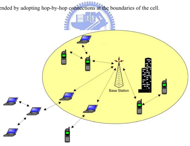
(10) Chapter 1 Introduction 1.1 Research Motivation and Purpose Multi-hop cellular networking has been an active research area in recent years. In conventional cellular networks, mobile stations communicate directly with their assigned base station; in wireless multi-hop networks, mobile stations are located randomly and use peer-to-peer communications to relay their messages. Multi-hop cellular networks that integrate the characteristics of both cellular and mobile ad hoc networks to leverage the advantages of each other have received increasing attention. Figure 1.1 indicates the scenario of general multi-hop cellular networks, the service area of the cellular networks can be extended by adopting hop-by-hop connections at the boundaries of the cell.. Figure 1.1 Scenario of general multi-hop cellular networks Much research has evaluated and summarized the benefits of such a hybrid architecture [1][4][7][8]: 1.
(11) z. The energy consumption of the mobile device can be conserved.. z. The interference with other nodes can be reduced.. z. The number of fixed antennas can be reduced.. z. The capacity of the cell can be increased.. z. The coverage of the network can be enhanced.. z. The robustness and scalability of the system can be increased.. In multi-hop cellular networks, data packets must be relayed hop by hop from a given mobile node to a base station and vice-versa [8]. Cooperation among nodes is an important prerequisite for the success of the relaying ad-hoc networks. In cooperating groups, such as emergency and military situations, all nodes belong to a single authority and therefore have a good reason to support each other. However, in the groups of anonymous participants, such as emerging civilian applications, the nodes do not belong to a single authority and cooperative behaviors can not be directly assumed [15]. Moreover, forwarding data for others incurs the consumption of battery energy and the delay of its own data, the assumption of spontaneous willingness to relay data is unrealistic for autonomous mobile nodes [16]. Consequently, providing incentives for the mobile nodes to cooperate as relaying entities in the groups of mutually unknown participants is reasonable. Much research [7-8, 15-22] has described how to stimulate intermediate nodes to forward data packets in multi-hop networks. The approaches can be classified into detection-based and motivation-based. The detection-based approach finds out misbehaving nodes and mitigates their impact in the networks. The motivation-based approach provides incentives to foster positive cooperation in ad hoc networks. Most works on the motivation-based approaches focus on its protocol and security aspects or just employ fixed-rate pricing on number of packets or volume of traffic forwarded. The major advantage. 2.
(12) of the fixed-rate pricing is that billing and accounting processes are simple. However, the price of the feedback incentives is independent of the actual state of the networks. Such system cannot react effectively to the dynamic and unpredictable variations of the wireless networks. Cost savings and service availability are two major concerns of a network provider adopting multi-hop cellular networking technology. In this research, we propose a dynamic incentive pricing scheme to maximize the revenue of the network provider while maintaining service availability in the networks. Monetary incentives not only affect the motivation of the intermediate nodes supporting relaying services but represent the costs of providing connection services in multi-hop cellular networks. If the price of the incentives is too low, the number of successful connections will be small and the network provider can not get adequate profit from the relaying networks. However, if the price of the incentives is too high, the network provider can not cover the costs from the fee charged from end users. Consequently, dynamically adjusting the price of the incentives based on the network conditions is more appropriate than fixed-rate pricing for the network provider to make maximum revenue. Since providing a uniform price of the incentives to all mobile nodes depending on the network situations neglects the distinct importance of each mobile node in the network topology, we also investigate how to give different amount of incentives for each mobile node that has different effects on supporting hop-by-hop connections. The base station should give more incentives to the nodes of high importance so that it can make more mobile nodes connect to the base station successfully. In order to react effectively to the individual impact of each mobile node on service availability, we present the concept of location-based incentive pricing for relaying services in multi-hop cellular networks. When a pre-constructed routing topology exists in the networks, the price of the feedback incentives for each. 3.
(13) intermediate node is adjusted according to the number of nodes that reside in its sub-tree. The willingness of an intermediate node relaying packets has a significant impact on the success of the multi-hop connections from all nodes in its sub-tree to the base station. The proposed pricing scheme shifts incentives from the nodes of low importance to the nodes of high importance in the routing topology so that it increases service availability without additional costs. When a pre-constructed routing topology is not available in the networks, a new metric called Quality-of-Relay (QoR) is defined to evaluate the importance of each mobile node affecting other nodes that require hop-by-hop connections to reach the central base station. Shifting incentives from the nodes of low importance to the nodes of high importance in the networks also enhances service availability with only a slight increase in relaying costs. In addition to adopting the QoR value for incentive pricing, we present a routing scheme based on the QoR value of each mobile node in the networks to select an optimal relaying path for connecting to the central base station. Although shortest path is the most simple and common metric used in the routing protocol, it may route almost packets over a few paths and result in network congestion and resource unavailable in hot spot. The routing scheme that selects a relaying path with minimum sum of the QoR values of all intermediate nodes in the path can retain more valuable resource for later relaying requests, thereby accepting more relaying connections under a certain constraint on maximum relaying capacity of each mobile node.. 1.2 Outline of This Thesis This thesis is organized into six chapters. Chapter 1 outlines the motivation and the research purpose. In Chapter 2, we review the existing multi-hop cellular network models and incentive approaches. Then, we introduce the general supply function for providing relaying services. In Chapter 3, a dynamic incentive pricing scheme is presented to maximize the 4.
(14) revenue of the network provider by adjusting the price of the feedback incentives based on the actual network conditions. Chapter 4 proposes a location-based incentive pricing scheme for relaying services with a tree-based routing topology. Chapter 5 describes Quality-of-Relay based incentive pricing and routing for relaying services without a pre-constructed routing topology. The pricing schemes presented in Chapter 4 and 5 encourage collaboration depending on the degree of each mobile node contributing to successful hop-by-hop connections. Finally, we conclude our research and suggest possible further research directions in Chapter 6.. 5.
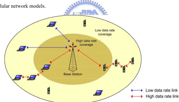
(15) Chapter 2 Literature Review 2.1 Multi-hop Cellular Network Model In conventional cellular networks, mobile stations communicate directly with their assigned base station and do not interact with other mobile stations inside the same cell. In wireless multi-hop networks, mobile stations are located randomly and use peer-to-peer communications to relay their messages in an ad hoc fashion. Although many approaches in the literature have been proposed to improve the performance of cellular networks and multi-hop networks in isolation, more and more research focuses on integrating the cellular and multi-hop network models. In this section, we present a survey of existing multi-hop cellular network models.. Figure 2.1 ODMA concept diagram. Opportunity Driven Multiple Access (ODMA) is a multi-hop relaying protocol that is used to increase the efficiency of Universal Mobile Telecommunication System (UMTS). In ODMA, the transmissions from mobile stations to the base station are broken into multiple. 6.
(16) wireless hops, thereby reducing transmission power. As the concept diagram illustrated in Fig. 2.1, the high-data-rate coverage of the cell can be increased at the boundaries by allowing mobile stations inside the original high-data-rate coverage area to act as relays for the mobile stations outside the high-data- rate coverage area [1-2]. Aggélou et al. describe an Ad Hoc GSM (A-GSM) system that presents a network layer platform to accommodate relaying capability in GSM cellular networks. Although the latest developments and experiments in GSM cellular networks aim to provide global roaming, there are still places where any present communication platform would fail to provide successful communication. These places, such as subway train platforms, indoor environments, and basements, are called dead spots. Since it is not economical to install additional antenna at each dead spot location, the authors integrate the standard GSM radio interface with sufficiently flexible capabilities to support relaying and extend communication at dead spot locations. Simulation results indicate that A-GSM multi-hop connections improve the system throughput for different mobile and dead spot populations [3]. Qiao et al. present a network model called iCAR that integrates the cellular infrastructure and ad-hoc relaying technologies. Limited capacity and unbalanced traffic are two fundamental problems in any cellular system. Some cells may be heavily congested while the other cells still have available channels. The localized congestion will cause call blocking and dropping even though the traffic load doesn’t reach the maximum capacity of the entire system. The proposed architecture places a number of Ad-hoc Relaying Stations (ARS) at strategic locations to relay data from one cell to another cell. The mobile host in a congested cell can use a channel available in a nearby cell, therefore increasing the system capacity as well as the channel efficiency. As the relaying example in the iCAR system indicated in Fig. 2.2, a mobile node initiates a new call in a congested cell A. The call will be blocked in an existing cellular system when no free channel is available in cell A. However, the mobile node. 7.
(17) can switch over to the relay interface to communicate with an ARS in cell B through other ARS’s in cell A in the iCAR system. Then the mobile node gets a free channel in cell B and sets up the call successfully. Load balancing among different cells in the iCAR system not only increases system capacity, but also reduces transmission power for mobile terminals [4].. Figure 2.2 A relaying example in the iCAR system ( Source: [4] ). Wu et al. propose a scheme called Mobile-Assisted Data Forwarding (MADF) to add an ad-hoc overlay to the fixed cellular infrastructure and special channels are assigned to connect users in a hot cell to its neighboring cold cells without going through the base station in the hot cell. The proposed method divides channels into forwarding channels and fixed channels. A mobile terminal in a hot cell may use the forwarding channels to transmit its data to a cold channel. An intermediate forwarding agent, such as a repeater or another mobile terminal, in the cold cell is required to relay the data to that cell. The authors find that under a certain delay requirement, the throughput can be greatly improved [5]. Luo et al. propose a Unified Cellular and Ad-Hoc Network (UCAN) architecture to enhance the cell throughput. Providing service to low-data-rate users is required for maintaining fairness, but at the cost of reducing the cell aggregate throughput. In the proposed method, each mobile device in the UCAN model has both 3G cellular link and IEEE 8.
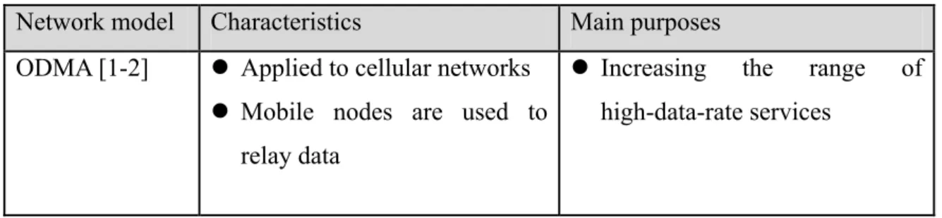
(18) 802.11-based peer-to-peer links. As the architecture indicated in Fig. 2.3, the 3G base station forwards packets for destination clients with poor channel quality to proxy clients with better channel quality. The proxy clients then use an ad-hoc network composed of other mobile clients and IEEE 802.11 wireless links to forward the packets to the destination, thereby enhancing cell throughput [6].. Figure 2.3 UCAN architecture ( Source: [6] ). Table 2.1 summarizes the characteristics and main purposes of the different multi-hop cellular network models. Table 2.1 Characteristics and main purposes of different multi-hop cellular network models Network model. Characteristics. Main purposes. ODMA [1-2]. z Applied to cellular networks. z Increasing. z Mobile nodes are used to relay data. 9. the. range. high-data-rate services. of.
(19) Network model. Characteristics. Main purposes. A-GSM [3]. z Applied to GSM cellular z Solving the problem of dead networks. spots. z Dual mode handsets are used. to. increase. system. throughput. to relay data iCAR [4]. z Applied to cellular networks. z Solving. z Special devices (ARS) are. the. limited. used to relay data. problems. capacity. of and. unbalanced traffic to increase system capacity. MADF [5]. z Applied to cellular networks. z Dealing with the problem of. z Mobile nodes or repeaters are used to relay data UCAN [6]. z Applied. to. fluctuating traffic in a cell to increase system throughput. cellular z Dealing with the problem of. 3G. networks. maintaining fairness and the. z Mobile nodes are used to relay data. cell. aggregate. throughput. simultaneously. Much research has evaluated and summarized the advantages of the multi-hop cellular networking architecture [1][4][7][8]: z. The energy consumption of the mobile node can be conserved.. z. The interference with other nodes can be reduced.. z. The number of fixed antennas can be reduced.. z. The capacity of the cell can be increased.. z. The coverage of the network can be enhanced.. z. The robustness and scalability of the system can be increased.. Although many benefits exist in the multi-hop cellular network model, the hybrid 10.
(20) architecture has some disadvantages as follows: z. The complexity of the mobile nodes will be enhanced for providing relaying services.. z. The battery consumption of the mobile node will be increased for forwarding packets.. 2.2 Routing Scheme in Multi-hop Cellular Network Model In multi-hop cellular networks, the communication between the base station and each mobile node is relayed by a number of other mobile nodes. Most of the multi-hop cellular networking models do not have a pre-constructed routing topology for relaying packets. The mobile nodes find relaying paths when they desire the path to transmit data. However, some studies have suggested that a tree-based routing topology is appropriate for multi-hop cellular networks because of the simple characteristic and authentication requirements. The packets simply follow the tree toward the destination. In this section, we review the routing schemes used in existing multi-hop cellular networks. We classify the routing schemes into z. Routing without a pre-constructed topology. z. Routing with a pre-constructed topology. 2.2.1 Routing without a Pre-Constructed Topology When a pre-constructed routing topology does not exist in multi-hop cellular networks, the mobile node initiates a route recovery process to find a hop-by-hop path to reach the base station depending on different criteria, such as signal strength, path length and power consumption. The routing scheme is similar to the routing approach adopted in pure ad hoc networks. Some research has reviewed and investigated existing multi-hop routing protocols, the 11.
(21) protocols can be classified into table-driven and demand-driven [23, 28-29]. Table-driven routing protocols attempt to maintain routing information from each node to every other node in the networks. On-demand routing (source-initiated) protocols create routes only when desired by the source node. The common approach in most existing routing protocols is to consider the shortest-path routing. For simplicity, these protocols measure the distance of the path by the number of hops in the path. However, routing packets based on minimum hop count may take a considerable time to reach the destination because it may route almost packets over a few (shortest-distance) paths in the networks [25]. The ODMA system does not build a routing topology in advance but let mobile nodes find the relying paths to the destination on demand. Previous work on ODMA uses path loss between terminals as the metric to determine the routing path [9-10]. From the list of relaying routes available, the one with minimum aggregate transmit power along the route is selected. This is often implemented by selecting the one with minimum path loss. Rouse et al. present a routing scheme considering receiver interference on ODMA [1]. In A-GSM system [3], handover is initiated by a mobile node when a high possibility exists that the call will be lost or the quality of the ongoing connection seriously degraded. The mobile nodes measure the signal strength of the surrounding A-GSM nodes and the connected base stations. When the criteria for changing the serving base station or the serving relay is satisfied, such as the existing serving base station failure, the A-GSM handover will be triggered. If multiple neighboring nodes are available for a mobile node to build a relaying path to the base station, the mobile node selects a relaying link with strongest signal to initiate handover. In iCAR system [4], a number of specific stations called ARS’s are deployed at strategic locations to relay data from the congested cell to the neighboring non-congested cells. Each ARS collects neighbor information and maintains a routing table containing one entry for. 12.
(22) every reachable Base Transmission Stations (BTS). The ARS reports this information to a Mobile Switching Center (MSC) that controls a number of BTS’s. The topology map can then be calculated by MSC’s and only the updated part relevant to the ARS’s is broadcast by the corresponding BTS to all ARS’s in the cell. Whenever a mobile node needs a relaying path to one or more BTS’s which have free channel available, the mobile node broadcast “route probe” message to all neighbor ARS’s for asking information on the relaying path to any of these BTS’s. After getting all replied relaying paths, the mobile node chooses the best ARS with the shortest path or the lowest power consumption as the proxy ARS to relay data to the target BTS. In MADF approach [5], a forwarding agent that is willing to forward data first measures the local traffic in its cell. If the traffic load is lower than a certain threshold, the forwarding agent will broadcast a ”free” signal to indicate its availability to relay data packets. The user in a hot cell collects the “free” signals and selects an agent according to the quality of the signal and the local traffic included in the “free” messages. In UCAN model [6], the authors propose greedy and on-demand protocols for proxy discovery and ad-hoc routing. Each mobile node maintains a moving average of its 3G downlink channel rate. In the greedy protocol, all mobile nodes maintain their immediate neighbors’ average downlink channel rates. When the route request message is issued, it is unicast to the neighbor with the highest downlink channel rate. The message then traverses greedily through the relay clients with increasing downlink channel quality and finally to the base station. In the on-demand protocol, mobile nodes do not maintain their neighborhood information. When the route request message is issued by a mobile node, it is broadcast to all its neighbors within a given range. The neighbor that has higher channel rate than the destination node writes its own channel rate into the route request message and forwards a copy of the message to the base station. After all route request messages arrive at the base. 13.
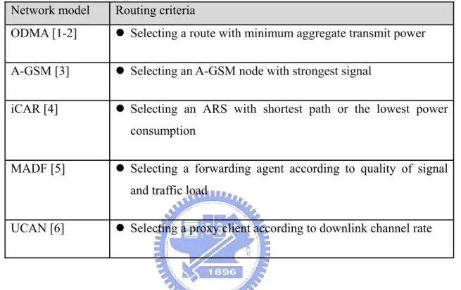
(23) station, the base station selects a mobile node with higher channel rate and shorter path length as the proxy client for the destination node. Table 2.2 lists the routing criteria adopted in different multi-hop cellular network models. Table 2.2 Routing criteria in different multi-hop cellular network models Network model. Routing criteria. ODMA [1-2]. z Selecting a route with minimum aggregate transmit power. A-GSM [3]. z Selecting an A-GSM node with strongest signal. iCAR [4]. z Selecting an ARS with shortest path or the lowest power consumption. MADF [5]. z Selecting a forwarding agent according to quality of signal and traffic load. UCAN [6]. z Selecting a proxy client according to downlink channel rate. 2.2.2 Routing with a Pre-Constructed Topology Some studies have suggested that a tree-based routing topology is appropriate for multi-hop cellular networks because of the simple characteristic and authentication requirements. A tree-based topology map for forwarding packets is pre-constructed in the egress node connected to the fixed backbone. The packets simply follow the routing topology toward the destination. Hsiao et al. propose an algorithm to construct a load-balancing routing tree for a wireless access networks. Via such a network, a mobile node, such as an information appliance, can send packets to and receive packets from an “egress node” that connects to the external networking infrastructure. The proposed tree-based routing approach can simplify routing by avoiding per-flow state and achieve better network utilization by lowering bandwidth 14.
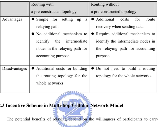
(24) blocking rates. Since the traffic model assumes that the primary mode of communications from wireless access networks will be access to the wired Internet, conventional per-destination routing information is not necessary. Outgoing packets from the nodes simply follow the tree toward the root, the egress node. Incoming packets follow explicit source-routed paths given by the egress node. The immediate routers aggregate load amount toward the root of the tree such that they do not maintain per-flow routing [11]. Zhang et al. present an IP-based virtual operator authentication, authorization and accounting (AAA) scheme in wireless LAN hot spots. The proposed solution can support accounting in the scenario where access points (AP) use ad-hoc networking to extend their service coverage. Packet-based accounting needs to properly identify the contributions of intermediate mobile nodes. In order to prevent collaborative cheating behaviors for getting feedback incentives, the authors suggest that a spanning tree rooted at the AP should be constructed to provide the routing path for any specific mobile node in cellular ad-hoc networks. The AP first determines all the mobile nodes that can be directly reached and includes these mobile nodes as trusted mobile nodes. Then the AP determines other mobile nodes that can be directly reach from the trusted nodes. Such a process is repeated until all reachable mobile nodes are included. Once the routing tree is determined, AP knows the branches and can figure out which mobile nodes are on the routing path for any specific mobile node [12]. Bejerano presents an efficient and low-cost infrastructure for connecting static multi-hop wireless networks with fixed backbone while ensuring Quality of Service (QoS) constraints such as bandwidth and delay. The proposed scheme divides the mobile nodes into clusters and selects a single access point at each cluster. A spanning tree rooted at the selected access point is used for message delivery to simplify the routing issue [13]. Table 2.3 compares the advantages and disadvantages of routing with a pre-constructed topology and routing without a pre-constructed topology in multi-hop cellular networks. 15.
(25) Table 2.3 Comparison between routing with a pre-constructed topology and routing without a pre-constructed topology in multi-hop cellular networks. Advantages. Routing with. Routing without. a pre-constructed topology. a pre-constructed topology. z Simple for setting up a z Additional relaying path. costs. for. route. recovery when sending data. z No additional mechanism to z Require additional mechanism to identify. Disadvantages. the. intermediate. identify the intermediate nodes in. nodes in the relaying path for. the relaying path for accounting. accounting purpose. purpose. z Additional costs for building z Do not need to build a routing the routing topology for the. topology for the whole networks. whole networks. 2.3 Incentive Scheme in Multi-hop Cellular Network Model The potential benefits of relaying depend on the willingness of participants to carry traffic for other parties [14]. In cooperating groups, such as emergency and military situations, all nodes belong to a single authority and therefore have a good reason to support each other. However, in the groups of anonymous participants, such as emerging civilian applications, the nodes do not belong to a single authority and cooperative behaviors can not be directly assumed. In addition, forwarding data for others incurs the consumption of battery energy and the delay of its own data, the assumption of spontaneous willingness to relay data is unrealistic for autonomous mobile nodes [15-16]. Consequently, providing incentives for the mobile nodes to cooperate as relaying entities in the groups of mutually unknown participants is reasonable. Much research has discussed the incentive schemes in pure ad-hoc or hybrid ad hoc networks. The approaches can be classified into detection-based and motivation-based. The 16.
(26) detection-based approach finds out misbehaving nodes and mitigates their impact in the networks. The motivation-based approach provides incentives to foster positive cooperation in ad hoc networks.. 2.3.1 Detection-based Incentive Approach Marti et al. describe two techniques to improve network throughput by detecting misbehaving nodes and mitigating their impact in networks [17]. A node may misbehave by agreeing to forward packets and then fails to do so, because it is overloaded, selfish, malicious or broken. Since even a few misbehaving nodes can be a significant problem, they use a watchdog to identify misbehaving nodes and a pathrater to avoid routing packets through theses nodes. When a node forwards a packet, the node’s watchdog verifies that the next node in the path also forwards the packet. As the topology indicated in Fig. 2.4, when B forwards a packet from S toward D through C, A can overhear B’s transmission and verify that B pass the packet to C. The solid line indicates the packet sent by B to C, while the dashed line represents that A is within transmission range of B and can overhear the packet transfer. The pathrater combines knowledge of misbehaving nodes with link reliability to select the relaying path. Although the proposed solution fosters cooperation in ad hoc networks, it does not castigate malicious nodes but rather mitigates the burden of forwarding for others.. Figure 2.4 Watchdog in detecting misbehaving nodes ( Source: [17] ). 17.
(27) Michiardi et al. suggest a mechanism called CORE based on reputation to enforce cooperation among nodes and prevent denial of service attacks due to selfishness [18]. Reputation is formed and updated along time through direct observations and information provided by other members of the community. Reputation directly related to the cooperative behavior of an entity is calculated based on subjective observations and indirect information provided by other members. Besides, the reputation can be evaluated according to different functions, such as packet forwarding and routing. The overall evaluation of reputation is computed by the weight associated to the functional reputation value from subjective observations and indirect information. The request from the entity with negative reputation will not be executed. There is no advantage for an entity to misbehave since any resource utilization will be forbidden. Buchegger et al. propose a protocol called CONFIDANT to detect and isolate misbehaving nodes, thus making it unattractive to deny cooperation [19]. Each node has four components: the Monitor, the Reputation System, the Path Manager and the Trust Manager. The Monitor detects deviations by the next node. The Trust Manager sends alarm messages to warn others of malicious nodes. The Reputation System manages a table consisting of entries for nodes and their rating. The rating is changed according to a rate function that assign different weights to the type of behavior detection. The weights for own experience are higher that for observations in the neighborhood. The Path Manager re-ranks the path according to the reputation of the nodes, deletes the path containing malicious nodes, and ignores the request for a route containing a malicious node. Non cooperating nodes are learnt from experienced, observed, or reported routing and forwarding behavior of other nodes. Both CORE and CONFIDANT discourage misbehavior by identifying and punishing misbehavior nodes. However, they do not involve using positive cooperation incentives in the proposed methods.. 18.
(28) 2.3.2 Motivation-based Incentive Approach Buttyán et al. use a virtual currency called nuggets as incentives given to cooperative nodes in every transmission [20]. Two approaches are proposed to reward intermediate nodes of packet forwarding: the Packet Purse Model and the Packet Trade Model. In the Packet Purse Model, the originator of the packet pays for the packet forwarding service. The source loads a number of nuggets in the packet and each intermediate node takes out nuggets for its forwarding service. As the example illustrated in Fig. 2.5, assume each node originally has 7 nuggets. Then, A loads 5 nuggets in the packet and sends it to the next hop B. B takes out 1 nugget from the packet and forwards it to the next hop C. Finally, C takes out 2 nuggets from the packet and forwards it to the destination D. Note that node B and C increase their stock of nuggets for forwarding the packet and node A decreases its stock of nuggets for originating the packet. The advantage of this model is that it discourages users from flooding the network but the problem is that it difficult to estimate the number of nuggets required for a given destination. In the Packet Trade Model, each packet is traded for nuggets by intermediate nodes. Each intermediate node buys the packet from the previous one for some nuggets and sells it to the next one for more nuggets on the path. As the example illustrated in Fig. 2.6, assume each node originally has 7 nuggets. Then, A sends the packet to the first hop B for free. B sells it to the next hop C for 1 nugget. Finally, C sells it to the destination D for 2 nuggets. Note that node B and C increase their stock of nuggets for forwarding the packet and node D decreases its stock of nuggets for receiving the packet. The advantage of this model is that the source does not need to know how many nuggets required to be loaded into the packet but malicious flooding of the network cannot be prevented [18]. Besides, the proposed models do not discuss the number of nuggets should be rewarded to the intermediate nodes.. 19.
(29) Figure 2.5 The Packet Purse Model ( Source: [20] ). Figure 2.6 The Packet Trade Model ( Source: [20] ). Buttyán et al. also propose a mechanism based on credit counter to stimulate packet forwarding [21]. Each node keeps track of its remaining energy and remaining number of nuggets. The nugget counter is decreased when the node sends an own packet, increased when the node forwards a packet. The number of feedback nuggets depends on the number of. 20.
(30) forwarding packets in this method. In [7], Jakobsson et al. present a micro-payment scheme that fosters collaboration and discourages dishonest behavior in multi-hop cellular networks. Packet originators associate subjective reward levels with packets according to the importance of the packet. Zhong et al. propose a system to provide incentives for mobile nodes to cooperate and report actions honestly [15]. The proposed system is a pure-software solution and do not require any tamper-proof hardware at any node. A central authority is in charge of collecting receipts from the forwarding nodes and then determining the charge or the reward to each node depending on the reported receipts. The system focuses on selfish nodes and determines payment and charges from a game-theoretic perspective. Lamparter et al. propose a charging scheme in hybrid cellular and multi-hop networks, which would be beneficial for Internet Service Provider (ISP) and the ad hoc nodes and thus motivates cooperation among mobile nodes [22]. The charging scheme is based on volume-based pricing models. A fixed price per unit is charged for sending or receiving traffic and is rewarded for forwarding traffic. The charging scheme is independent of the network conditions. In [8], the authors propose an incentive mechanism based on a charging/rewarding scheme in multi-hop cellular networks and that makes collaboration rational for selfish nodes. The solution relies exclusively on symmetric cryptography to compliant with the limited resources of the mobile stations. In the proposed method, both the charge of sending the data packet and the reward of forwarding the data packet depend on the packet size and not on the number of forwarding nodes in the path. From above reviews, we find most works on the motivation-based approaches focus on its protocol. The proposed incentive methods associate subjective reward levels or employ fixed-rate pricing on number of packets or volume of traffic forwarded.. 21.
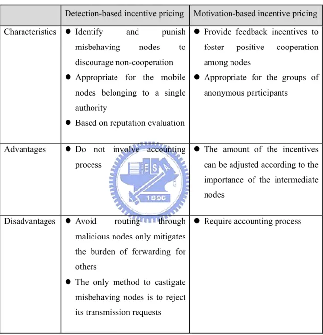
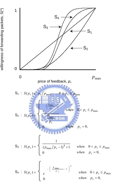
(31) Table 2.4 summarizes the difference between detection-based incentive pricing and motivation-based incentive pricing. Table 2.4 Comparison between detection-based incentive pricing and motivation-based incentive pricing Detection-based incentive pricing Characteristics z Identify. punish z Provide feedback incentives to. and. misbehaving. Motivation-based incentive pricing. nodes. to. discourage non-cooperation. foster. positive. cooperation. among nodes. z Appropriate for the mobile z Appropriate for the groups of nodes belonging to a single. anonymous participants. authority z Based on reputation evaluation Advantages. z Do not involve accounting z The amount of the incentives process. can be adjusted according to the importance of the intermediate nodes. Disadvantages. z Avoid. routing. through z Require accounting process. malicious nodes only mitigates the burden of forwarding for others z The only method to castigate misbehaving nodes is to reject its transmission requests. 2.4 Supply Function for Providing Relaying Services Pricing is an inducer for suppliers to provide services. Monetary incentives can affect the motivation of mobile nodes providing services and is usually characterized by a supply function that represents the reaction of mobile nodes to the change of the price [26]. The 22.
(32) general supply function describes that the producers are willing to produce more goods as the price goes up. Herein we consider four forms for the supply function as follows [27]: S1: S ( p v ) = p v p max , 0 ≤ p v ≤ p max ,. e S2: S ( p v ) =. ⎞ ⎛ Pmax − ⎜⎜ −1 ⎟⎟ ⎠ ⎝ pv. (1). 2. when 0 < p v ≤ p max. Pmax pv. when. 0. (2). p v = 0,. 1. S3: S ( p v ) = ( p max p v − 1) 4 + 1 when 0 < p v ≤ p max when p v = 0, 0. S4: S ( p v ) = e 0. ⎞ ⎛P − ⎜⎜ max −1 ⎟⎟ ⎠ ⎝ pv. (3). 2. when 0 < p v ≤ p max when. (4). p v = 0,. where p max is the maximum price that network provider can feedback, pv is the price of the feedback incentives for node v per unit of relay data. S ( p v ) denotes the possibility of node v accepting the price to forward data packets. Note that S (0) = 0 , which means that node v will not relay traffic for others if no feedback is provided for relaying services. The willingness of forwarding packets increases as the price of feedback increases. For pv = p max , we have S ( p max ) = 1 , which means that the maximum price is acceptable to all mobile nodes to provide relaying services. Figure 2.7 illustrates the difference between the four supply functions with various supply flexibility. S 1 represents a linear relationship between price of feedback and willingness of forwarding packets. S 2 , S 3 and S 4 begin low for small pv , 23.
(33) then increase rapidly as pv gets into a mid-range. When prices are low, S 1 is more sensitive to price changes. When prices are in the middle range, S 3 and S 4 are much more. willingness of forwarding packets, S(*). sensitive than the others to small price changes.. 1000. 1. S4 S3 S1. S2. 00 0. 1000 p max. 0 price of feedback, pv. S1 : S ( p v ) = pv pmax. S2 : S ( p v ) =. e. , 0 ≤ pv ≤ pmax. ⎛ Pmax ⎞ −⎜ −1 ⎟ ⎜ ⎟ ⎝ pv ⎠. when. 0 < pv ≤ pmax. when. pv = 0,. Pmax pv 0. 1. S3 : S ( p v ) =. S4 : S ( p v ) =. ( pmax pv − 1) 4 + 1. when. 0 < pv ≤ p max. 0. when. pv = 0,. e. ⎛ P max − ⎜⎜ p v ⎝. ⎞ − 1 ⎟⎟ ⎠. 2. when 0 < pv ≤ pmax when. 0. pv = 0,. Figure 2.7 Four supply functions of price of feedback and willingness of forwarding packets. 24.
(34) Chapter 3 Dynamic Incentive Pricing in Multi-hop Cellular Networks Cost savings and service availability are two major concerns of a network provider adopting multi-hop cellular networking technology because fewer base stations might be required but more customers could be served. Much research has discussed how to stimulate intermediate nodes to provide relaying services in multi-hop cellular networks, but most of them use static incentive pricing schemes and do not consider the current state of the networks. In this chapter, we present a dynamic incentive pricing scheme to maximize the revenue of the network provider. The proposed scheme adjusts the price of the feedback incentives based on the actual network conditions to influence the relaying capability of the network and therefore increases the revenue of the network provider. Besides, we investigate how to maximize the revenue of the network provider while ensuring Quality of Service (QoS) requirements such as new call blocking probability.. 3.1 Dynamic Incentive Pricing Scheme for Relaying Services Herein we focus only on a single base-station cell as indicated in Fig. 3.1. We define the relaying capability ( RC ) of the network as the percentage of the relaying service area in which mobile nodes can connect to the base station through peer-to-peer communications. Cooperation among nodes plays a critical role in the success of the multi-hop cellular networks, therefore the number of cooperative nodes has a significant impact on the relaying capability of the multi-hop cellular networks. We build a simulation model to observe the influence of the number of cooperative nodes on the relaying capability of the network when mobile nodes are randomly located inside the service area of the base station. As the relationship illustrated in Fig. 3.2, the relaying capability of the network increases as the number of cooperative nodes. 25.
(35) increases.. Figure 3.1 Networking model. Relaying Capability of the Network. 1 0.9 Relay ing Serv ice Area = 1000 units * 1000 units Radius of Base Station = 250 units Radius of Mobile Station = 100 units. 0.8 0.7 0.6 0.5 0.4 0.3 0.2 0.1 0 0. 40. 80. 120. 160. 200. 240. 280. 320. 360. 400. 440. 480. 520. 560. 600. Number of Cooperativ e Nodes. Figure 3.2 The relationship between the relaying capability of the network and the number of cooperative nodes. From above observation, we define the relaying capability of the network RC as a function of the number of cooperative nodes n , i.e., RC = f (n) , f (n) is a function of n with the following properties:. 0 ≤ f (n) ≤ 1;. f (n = 0) = 0;. lim n → ∞ f (n) = 1 .. (5). Monetary incentives can affect the motivation of mobile nodes providing services. Here we use supply function S4 to describe the reaction of mobile nodes to the change of the price.. 26.
(36) S ( pt ) =. e. ⎞ ⎛ p − ⎜⎜ max −1 ⎟⎟ ⎠ ⎝ pt. (6). 2. 0. when. 0 < pt ≤ p max. when. pt = 0.. Let p t denotes the price of the feedback incentives per unit of relay data at time t , p max is the maximum price that the network provider can feedback, S ( pt ) denotes the percentage of mobile nodes that will accept the price to forward data packets. Note that S ( p max ) = 1 , which means that the maximum price is acceptable to all mobile nodes to provide relaying services. For pt = 0 , we have S (0) = 0 , which means that no mobile node is willing to relay traffic for others if no feedback is provided for relaying service. Let p t denotes the price of the feedback incentives, N t be the number of mobile nodes and RC t be the relaying capability of the network at time t . From our observation, RC t is a function of the number of cooperative nodes that depends on total number of mobile nodes and their willingness to support relaying services, that is, RCt = f ( N t S ( pt )) .. (7). Assume K t is the number of mobile nodes that request data transmission at time t . The availability of the relaying paths is determined by RC t , thus the number of successful connections M t at time t is given by M t = K t RC t .. (8). Assume the static usage-based charging model is accepted by the end users, i.e. end users agree to pay the network provider (base station) a fixed price u , per unit of data transmitted in each hop. Let vi be the unit of data sent by user i , hi be the number of hops exists between user i and the base station at time t , the revenue from the service for user i is (u − p t )hi v i . Since the base station is interested in maximizing its revenue, the corresponding maximization problem at time t is given as follows: 27.
(37) (9). Mt. Maximize R = ∑ ((u − p t )hi v i ) i =1. Subject to: M t = K t RCt = K t f ( N t S ( pt )). S ( pt ) =. e. ⎞ ⎛ u − ⎜⎜ −1 ⎟⎟ ⎠ ⎝ pt. 0. 2. when. 0 < pt ≤ u. when. pt = 0.. In order to maximize the revenue, the network provider should increase p t to enhance the relaying capability of the network and therefore increase the number of successful connections. However, the increase in p t will decrease the revenue (u − p t )hi v i from user i . Consequently, the network provider should dynamically adjust p t based on the actual. network conditions to maximize the revenue. For p t = 0 , we can obtain M t = K tf ( N t S ( pt = 0)) = 0 , and for p t = u , we can obtain M t = K tf ( N t S ( pt = u )) = K t f ( N t ) ≤ K t . For i = 1,..., M t , the revenue (u − p t )hi v i received. from user i decreases as p t increases. For p t = 0 , we have (u − p t )hi v i = uhi v i , and for p t = u , we have (u − pt )hi vi = 0 .. Since both M t and (u − p t )hi v i have a minimum and a maximum value over the closed Mt. interval pt ∈ [0, u ] , R = ∑ ((u − p t )hi v i ) also has a minimum and a maximum value over the i =1. same interval. From the above discussion, the minimum value is obtained at the endpoints of the closed interval. Specifically, R is zero either when p t = 0 , which corresponds to the case that no successful relaying connection exists in the networks, or when p t = u , which corresponds to the case that the charges from end users are equal to the costs of providing relaying services. Let Rtm be the maximum value of the revenue of the network provider at time t . From above analysis, we conclude that there exists at least one p t value(s), denoted by p ti 28.
(38) ( i = 0,1,... ), over interval (0, u ) such that: R( pt = pti ) = Rtm .. (10). If only one p ti exists that satisfies (10), the optimal price of the feedback incentives is p t* = p t0 . If more than one different values of p ti satisfy (10), we set the optimal price of the. feedback incentives to be pt* = sup i∈{0,1,...} { pti | R ( p ti ) = Rtm } , which is the highest price of the feedback incentives that can maximize the total revenue of the network provider. The reason we select the maximum p ti is that the number of successful connections increases as the price of the feedback incentives increases, therefore the network provider can support relaying services with a lower new call blocking probability.. 3.2 Dynamic Incentive Pricing Scheme for Relaying Services with QoS Constraints In this section, we add a constraint in the model to maximize the revenue of the network provider while ensuring Quality of Service (QoS) requirements. We define the QoS metric Levelqos as follows:. (11). Levelqos = 1 − Pb .. where Pb is the new call blocking probability. In order to maintain the QoS metric Levelqos above the required level L , the corresponding maximization problem at time t is modified as follows: (12). Mt. Maximize R = ∑ ((u − p t )hi v i ) i =1. Subject to: M t = K t RCt = K t f ( N t S ( pt )). 29.
(39) S ( pt ) =. e. ⎞ ⎛ u − ⎜⎜ −1 ⎟⎟ ⎠ ⎝ pt. 0. 2. when. 0 < pt ≤ u. when. pt = 0,. Levelqos ≥ L. The QoS metric Levelqos substantially depends on the price of the feedback incentives for relaying services. The lower the price of the feedback incentives, the lower the willingness of forwarding packets. Therefore a large number of calls will be blocked, which is also a great penalty to the QoS. Consequently, the network provider should set a threshold of the price of the feedback incentives based on actual network condition to meet QoS requirements. Since the acceptable threshold of the price for the network provider with the desired QoS level L and the number of total mobile nodes N t at time t is TPLN t ∈ [0, u ] and the revenue R has a maximum value over the closed interval pt ∈ [0, u ] , we can observe that R has a maximum value over the interval [TPLN t , u ] .. 3.3 Simulation Model In this section, we evaluate the performance of the proposed dynamic incentive pricing scheme in terms of the revenue of the network provider and new call blocking probability. The parameters used throughout our performance evaluation are as follows: z. A rectangular region of size 1000 units by 1000 units with a single base station located in the central point and various number of randomly distributed mobile nodes is used as the network topology. The radius of the base station is 250 units and the radius of each mobile node is 100 units.. z. The number of active mobile nodes in the service area is varied with time. The variation of the number of the active mobile nodes during a 24-hour period used through out our study is indicated in Fig. 3.3. 30.
(40) Number of active mobile nodes. 600 550 500 450 400 350 300 250 200 150 100 50 0 0. 2. 4. 6. 8 10 12 14 16 18 20 22 24 Time. Figure 3.3 Number of active mobile nodes in the simulation area. z. We assume all nodes in the relaying area request data transmissions to the base station. The volume of the data sent is randomly distributed between 0 and 100 units.. z. For finding a successful connection between each mobile node and the base station, the shortest path routing protocol is used.. z. In the following numerical study, we use the supply function as following:. S ( pt ) =. e 0. ⎛ u ⎞ − ⎜⎜ −1 ⎟⎟ ⎝ pt ⎠. (13). 2. when. 0 < pt ≤ u. when. pt = 0.. where u is the price per unit of data transmitted in each hop charged from end users, and is also the maximum price that network provider willingly to feedback to the intermediate nodes for relaying services. z. The 24-hour period is divided into 10-minute sections. At the end of each section, the optimal price pt* of the feedback incentives to maximize the revenue is calculated.. 31.
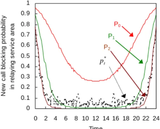
(41) 3.4 Simulation Results and Discussions We compare the proposed dynamic incentive pricing scheme with the static incentive pricing scheme. We use p 0 ( S ( p0 ) = 0.25 ), p1 ( S ( p1 ) = 0.5 ), and p 2 ( S ( p2 ) = 0.75 ) as the fixed prices, which represent that 25 percent, 50 percent and 75 percent of the mobile nodes will accept this fixed price to forward data for others. Figures 3.4 and 3.5 demonstrate the simulation results by using (9) to determine the optimal price of the feedback incentives in the revenue maximization problem without QoS constraints. 1.5 * * P(t)/P t 11 t. pp / p. 1.4 1.3 1.2. 40000. *. Revenue ( /u ). 50000. p*t / /pPp11 optimal price pP(t)/Po t 1. 60000. 1.1 1. 30000. 0.9 20000. 0.8. P2. 10000. 0.7. P(t) *. pt. P1 P0. 0.6 0.5. 0 2. 4. 6. 8. 10 12 14 16 18 20 22 24 Time. Figure 3.4 Optimal price and revenue of the network provider for different pricing schemes. New call blocking probability in relaying service area. 1 0.9. P0. 0.8 0.7. P1. 0.6. P2. 0.5. P(t) p* t. 0.4 0.3 0.2 0.1 0 0. 2 4. 6. 8 10 12 14 16 18 20 22 24 Time. Figure 3.5 New call blocking probability in relaying service area for different pricing schemes. Figure 3.4 depicts how the price is adjusted according to the change of the network conditions during the 24-hour period. When the number of the cooperative nodes increases, i.e.. 32.
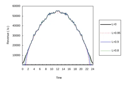
(42) the relaying capability of the network increases, the network provider should decrease the price ( pt* / p1 ) of the incentives to maximize its revenue. Figure 3.4 also illustrates the revenue of the network provider by adopting the proposed scheme and the three static pricing schemes respectively. We find that the proposed pricing scheme results in higher revenue of the network provider than the static pricing schemes. Figure 3.5 indicates the new call blocking probability in the relaying service area for different pricing schemes. We find that the proposed pricing scheme has more revenue but does not cause a high new call blocking probability. Figures 3.6 and 3.7 demonstrate the simulation results by using (12) to determine the optimal price of the feedback incentives and the maximum revenue of the network provider. Figure 3.6 depicts how the proposed pricing scheme adjusts the price of feedback incentives when QoS requirements L are 0.95, 0.8, 0.85 and 0 respectively. L=0 implies that the QoS level is not required in the pricing model. The optimal prices of incentives in the pricing model with QoS constraints are higher than that without QoS constraints. When fewer mobile nodes exist in the service area, the network provider should increase the optimal price of feedback incentives to satisfy the required QoS level. Because rewarding more incentives can increase the proportion of mobile nodes that willingly provide relaying services. Figure 3.7 indicates that the maximum revenue of the network provider is less when fewer mobile nodes exist in the service area. Because more incentives should be provided for relaying entity to maintain the desired QoS level, this increases relaying costs and decreases the revenue of the network provider.. 33.
(43) 1.7 1.6. optimal price P(t)/Po pt* / p1. 1.5 L=0. 1.4. L=0.9. 1.3 1.2. L=0.8. 1.1 L=0.95. 1.0 0.9 0.8 0. 2. 4. 6. 8. 10. 12 14. 16 18. 20 22. 24. Time. Figure 3.6 Optimal price of incentives under different QoS requirements. 60000. Revenue ( /u ). 50000 L=0. 40000. L=0.95. 30000. L=0.9 20000 L=0.8 10000. 0. 2. 4. 6. 8. 10 12 14 16 18 20 22 24 Time. Figure 3.7 Maximum revenue of the network provider under different QoS requirements. 3.5 Summary Cost savings and service availability are the primary concerns that the network provider adopts multi-hop cellular networking technology. In this chapter, we present a dynamic incentive pricing scheme to maximize the revenue of the network provider. The proposed scheme adjusts the price of the feedback incentives based on the actual network conditions to affect the relaying capability of the network and therefore increases the revenue of the network 34.
(44) provider. The simulation results demonstrate that the revenue can be increased by dynamically adjusting the price of the incentives for relaying services. Furthermore, the proposed pricing scheme does not cause a high new call blocking probability in relaying service area.. 35.
(45) Chapter 4 Location-based Incentive Pricing with a Tree-based Routing Topology 4.1 Location-based Incentive Pricing Scheme for Relaying Service Some studies have suggested that tree-based routing is appropriate for multi-hop cellular networks because of the simple characteristic and authentication requirements. In this chapter, we propose a location-based incentive pricing scheme to encourage collaboration based on the degree of each mobile node contributing to successful hop-by-hop connections. Our focus here is on the incentive pricing scheme to enhance service availability but do not cause higher costs. Since we assume the tree-based routing topology is used in multi-hop cellular networks, the proposed scheme adjusts the price of feedback incentives for each intermediate node according to the number of nodes that reside in its sub-tree. The proposed pricing scheme shifts incentives from the nodes of low importance to the nodes of high importance in the routing topology so that it increases service availability without additional costs. Assume a tree-based topology for packets delivery is pre-constructed by the central base-station as indicated in Fig. 4.1. In order to evaluate the important degree of the location for each mobile node, we define the location index of a mobile node v , denoted by LI v , as the number of nodes that reside in the tree rooted at node v . Because node v is one of the intermediate nodes on the paths from all nodes in its sub-tree to the base station, the willingness of node v for relaying packets has a significant impact on the success of the multi-hop connections from all nodes in its sub-tree to the base station. Therefore LI v is defined in proportion to the number of nodes affected by node v . As the tree-based relaying topology depicted in Fig. 4.1, the respective location indices of node a, c, f, g, h, j are 4, 2, 3, 2, 1, 2 according to the definition of location index.. 36.
(46) Figure 4.1 An example of tree-based relaying topology in multi-hop cellular networks. Let N be the set of intermediate nodes providing relaying services for mobile nodes that require hop-by-hop connections to the base station, ALI be the average location index of all nodes in N , that is, ALI = (∑ LI v ) /(∑ 1) . v∈ N. (14). v∈ N. Then, the proposed location-based incentive pricing scheme assigns the price of the feedback incentives for node v , pv , as follows, p v = p 0 + ( LI v − ALI ) *. Rp R LI. *. 1 LI v. (15). where R p = min{ p 0 , p max − p 0 } R LI = max { ALI − min {LI v }, max {LI v } − ALI } . v∈N. v∈N. p0 is the price adopted in the fixed-rate pricing method, the proposed scheme employs p0 as a basic price and derives pv according to the difference between LI v and the average. 37.
(47) location index ALI . The parameter R p R LI is used to make pv in the interval [ 0, p max ]. The parameter 1 LI v aims to balance total costs of feedback.. 4.2 Location-based Pricing v.s. Fixed-rate Pricing In this section, we compare the proposed location–based pricing scheme with fixed-rate pricing scheme by the total costs of the feedback incentives and the service availability of the networks.. 4.2.1 Total Costs of Feedback Incentives. Assume each mobile node that requires relaying connections has identical traffic load u . Since LI v is equal to number of nodes sending data through node v , the total costs of feedback for intermediate nodes in the fixed-rate pricing scheme with price p 0 is given by ∑ (u * LI v * p0 ) .. (16). v∈N. The set N of nodes can be divided into three subsets: N LI < ALI where location index of the node is below ALI , N LI = ALI where location index of the node is equal to ALI , and N LI > ALI where location index of the node is above ALI . The total costs of feedback in the proposed pricing scheme with basic price p 0 is given by. ∑ (u * LI v * ( p 0 − ( ALI − LI v ) *. v∈ N LI < ALI. Rp R LI. + ∑ (u * LI v * ( p 0 + ( LI v − ALI ) * v∈ N LI > ALI. =. (. *. Rp R LI. 1 )) + ∑ (u * LI v * p 0 ) v∈ N LI v LI = ALI. *. 1 )) LI v. ∑ (u * LI v * p 0 ) + ∑ (u * LI v * p 0 ) + ∑ (u * LI v * p 0 ). v∈N LI < ALI. v∈ N LI = ALI. v∈ N LI > ALI. 38. (17). ).
(48) +. =. (. u * Rp R LI. (. ∑ ( LI v − ALI ) − ∑ ( ALI − LI v ). v∈N LI > ALI. v∈N LI < ALI. ). ∑ (u * LI v * p 0 ) + ∑ (u * LI v * p 0 ) + ∑ (u * LI v * p 0 ) ) +. v∈N LI < ALI. v∈ N LI = ALI. v∈ N LI > ALI. u * Rp R LI. *0. = ∑ (u * LI v * p 0 ) . v∈N. From above computation, we can find that the total costs of the feedback incentives in the proposed pricing scheme is equal to that in the fixed-rate pricing scheme.. 4.2.2 Service Availability. Let M x be the set of intermediate nodes on the path from node x to the base station in the pre-constructed routing topology and PAx be the path availability between node x and the base station. In multi-hop cellular networks, data packets must be relayed hop by hop from a given mobile node to a base station, thus the path availability from a mobile node to the base station depends on the individual willingness of each mobile node to forward packets on the routing path, that is, PAx =. ∏ S( p ) .. v∈M x. (18). v. Since networking services provided by the base station are available when the mobile nodes can connect to the base station successfully, we define the service availability of the whole relaying networks as the average path availability of all mobile nodes using relaying connections. Let K be the set of the mobile nodes that require hop-by-hop connections to the base station, the service availability of the whole relaying networks is defined as follows: SA = ( ∑ PAx ) /( ∑ 1) . x∈K. (19). x∈K. Consider the relaying topology indicated in Fig. 4.1, the location-based pricing scheme 39.
數據
![Figure 2.2 A relaying example in the iCAR system ( Source: [4] )](https://thumb-ap.123doks.com/thumbv2/9libinfo/8580393.189333/17.892.156.786.273.727/figure-relaying-example-icar-source.webp)
+7
相關文件
The stereo matching techniques developed in the computer vision community along with ima ge-based rendering (view interpolation) tech niques from graphics are both essential
In this chapter, a dynamic voltage communication scheduling technique (DVC) is proposed to provide efficient schedules and better power consumption for GEN_BLOCK
In this chapter, we have presented two task rescheduling techniques, which are based on QoS guided Min-Min algorithm, aim to reduce the makespan of grid applications in batch
In this thesis, we have proposed a new and simple feedforward sampling time offset (STO) estimation scheme for an OFDM-based IEEE 802.11a WLAN that uses an interpolator to recover
In this thesis, we propose a novel image-based facial expression recognition method called “expression transition” to identify six kinds of facial expressions (anger, fear,
In this chapter, the results for each research question based on the data analysis were presented and discussed, including (a) the selection criteria on evaluating
A decision scheme based on OWA operator for an evaluation programme: an approximate reasoning approach. A decision scheme based on OWA operator for an evaluation programme:
Abstract: This paper presents a meta-heuristic, which is based on the Threshold Accepting combined with modified Nearest Neighbor and Exchange procedures, to solve the Vehicle
