Architecture Design of Context-Based Adaptive
Variable-Length Coding for H.264/AVC
Tung-Chien Chen, Yu-Wen Huang, Chuan-Yung Tsai, Bing-Yu Hsieh, and Liang-Gee Chen, Fellow, IEEE
Abstract—Context-based adaptive variable-length coding (CAVLC) is a new and important feature of the latest video coding standard, H.264/AVC. The direct VLSI implementation of CAVLC modified from the conventional run-length coding architecture will lead to low throughput and utilization. In this brief, an efficient CAVLC design is proposed. The main concept is the two-stage block pipelining scheme for parallel processing of two 4 4 blocks. When one block is processed by the scanning engine to collect the required symbols, its previous block is han-dled by the coding engine to translate symbols into bitstream. Our dual-block-pipelined architecture doubles the throughput and utilization of CAVLC at high bit rates. Moreover, a zero skipping technique is adopted to reduce up to 90% of cycles at low bit rates. Last but not least, Exp-Golomb coding for other general symbols and bitstream encapsulation for the network abstraction layer are integrated with CAVLC as a complete H.264/AVC baseline profile entropy coder. Simulation shows that our design is capable of real-time processing for 1920 1088 30-fps videos with 23.6 K logic gates at 100 MHz.
Index Terms—Context-based adaptive variable-length coding (CAVLC), H.264/AVC, VLSI architecture.
I. INTRODUCTION
T
HE new video coding standard H.264/AVC [1] signif-icantly outperforms previous standards in compression performance. It aims at a wide range of applications such as storage, entertainment, multimedia short message, videophone, videoconference, HDTV broadcasting, and Internet streaming. Compared with MPEG-4 [2], H.263 [3], and MPEG-2 [4], H.264/AVC can achieve 39%, 49%, and 64% bit-rate reduc-tions, respectively [5].The framework of H.264/AVC still belongs to block-based motion-compensated transform coding similar to previous stan-dards. The better compression performance mainly comes from the prediction and entropy coding tools [6]. However, the new features cause not only much higher computational complexity but also have a great impact on the traditional architectures for low-cost and high-performance considerations. Many fast algo-rithms [7], architectures [8], [9], and system considerations [10], [11] have been developed for H.264/AVC. In this brief, we will focus on the entropy coding.
Manuscript received December 9, 2004; revised April 11, 2005. This work was supported by the National Science Council, Taiwan, R.O.C., under Grant 95PFA0106257. This paper was recommended by Associate Editor A. Loui.
The authors are with the DSP/IC Design Laboratory, Department of Electrical Engineering and Graduate Institute of Electronics Engineering, National Taiwan University, Taipei 106, Taiwan, R.O.C. (e-mail: [email protected]; [email protected]; [email protected]; [email protected]. ntu.edu.tw; [email protected]).
Digital Object Identifier 10.1109/TCSII.2006.880014
The baseline profile entropy coding tools are context-based adaptive variable-length coding (CAVLC) for quantized trans-form residues and Exp-Golomb coding for the other syntax elements. In previous standards, entropy coding of residues is based on forward zig-zag scanned run-length coding and fixed variable-length coding (VLC). To further enhance the com-pression performance, H.264/AVC adopts backward zig-zag scanned run-length coding and adaptive VLC. In CAVLC, the intersymbol correlations are used to remove more statistical redundancy by switching VLC tables depending on previously transmitted symbols. According to our instruction profile and symbol analysis, entropy coding will exhaust the resource of the system processor if implemented by software, not to mention higher specifications as SDTV and HDTV. Besides, entropy coding involves many bit-level operations that cannot be efficiently executed by general purpose processors. Some hardware accelerating solutions have been proposed [12], [13]. However, [12] just discussed the decoding part. The directly unfolded CAVLC engine in [13] results in large area and long critical path.
In this brief, an efficient hardware solution is proposed. Three critical issues of H.264/AVC baseline profile entropy coding are addressed. First, due to the block-based context formation in CAVLC, the scanning and coding cannot be smoothly pipelined coefficient by coefficient. The information of a 4 4 block should be buffered, and the coding procedure has to wait for the scanning. At high bit rates, the number of cycles for coding is close to that for scanning, which halves the hardware utilization and throughput. Second, at low bit rates, many blocks are all-zero. Scanning these blocks is a waste of time and power. Third, encapsulation from the video coding layer (VCL) to the network abstraction layer (NAL) requires a second pass at reading, insertion, and writing of the entire bitstream, thus significantly increasing the bus bandwidth if handled by the system processor. In order to overcome the design challenges, a dual-block-pipelined architecture, a coded block pattern (CBP) look-ahead scheme, and a 96-b packer are proposed with good simulation results to prove our main concepts, which will be described later.
The remainder of this brief is organized as follows. In Section II, the background is reviewed. Section III describes the architecture design of H.264/AVC baseline profile entropy coding. Section IV shows the VLSI implementation of the entropy coder. Finally, a conclusion is drawn in Section V.
II. FUNDAMENTALS
Here, the bitstream hierarchy and CAVLC will be briefly re-viewed. For other details, please refer to [1] and [6].
Fig. 1. Basic hierarchy of bitstream in baseline profile.
A. Bitstream Hierarchy and Block Coding Order
Fig. 1 shows the hierarchical structure of a bitstream. The entire sequence can be categorized into four layers: sequence, slice, macroblock (MB), and block. The first three layers begin with headers. The sequence parameter set and picture parameter set (SPS/PPS) define the coding tools and sequence informa-tion, such as profile, level, frame size, and frame number. The slice header represents the slice information such as slice mode and initial quantization parameter. The MB header represents the MB information such as block types, prediction modes, and motion vectors (MVs). After the MB header, residues of an MB are divided into several 4 4 blocks and 2 2 blocks, and then these blocks are coded by CAVLC.
B. Context-Based Adaptive VLC
Conventional residue coder scans a block in a forward zig-zag order (from the dc to the highest ac). Once a nonzero residue is found, the number of preceding zeros (known as run) and the nonzero residue (known as level) are transmitted as a joint symbol. An end-of-block (EOB) or related last-jointed run-level symbol will terminate the bitstream of a block if the remaining residues are zeros. The scanning phase and the coding phase can be fully pipelined for every residual pixel.
In CAVLC, a block is scanned in a backward zig-zag order (from the highest ac to the dc). The first symbol represents the number of total nonzero coefficients (TCs) and the number of trailing ones (T1s). The following symbols are signs of trailing ones, levels, number of total zeros (T0s, excluding the zeros after the last nonzero coefficient in the forward zig-zag order), and runs. Since the last several nonzero residues are usually in the unit magnitude, the T1s with sign symbols can replace the level symbols of trailing ones for fewer bits. With TCs and T0s, the EOB is not required. Besides, when the transmitted runs reaches T0s, the runs for the rest levels must be zeros and thus can be saved. When the last level is reached, the run of the last level must be equal to T0s minus all previous runs and thus can be saved as well.
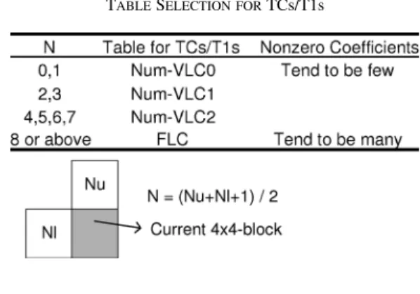
In addition to the reduction of symbol amount, context-based adaptability is the most important key to improve the entropy coding performance. In CAVLC, each category of symbols has several context-based adaptive VLC tables, and the selection of these tables depends on the statistics of the block’s con-tent and previous transmitted symbols to match the most prob-able statistics. For example, there are four TCs/T1s look-up tables (LUTs) denoted Num-VLC0, Num-VLC1, Num-VLC2, and FLC in Table I. Since the TC’s symbols of neighboring
TABLE I
TABLESELECTION FORTCs/T1s
TABLE II
ADAPTIVEFACTORS OFEACHSYMBOL INCAVLC
blocks are usually correlated, the selection of tables depends on , the average number of TCs values in the upper block and the left block. The Num-VLC0 table is designed for blocks with few nonzero coefficients, and the bit length of a codeword with smaller TCs/T1s is shorter. As for levels, there are seven adap-tive VLC tables. Table II lists the adapadap-tive factors of each cate-gory of symbols.
III. ARCHITECTUREDESIGN
A. Profiling and Analysis
We use iprof to make instruction profiling for [14] on a processor-based platform (SunBlade 2000 workstation with Ultra Sparc II 1.015 GHz with 8-GB RAM running SunOS 5.9). The profiling is for an H.264/AVC baseline profile encoding among four CIF 30 fps videos (i.e., Foreman, Stefan, Weather, and Mobile-Calendar) with a quantization parameter of 20. The entropy coder requires 115.4 MIPS of computing power in average, which is a heavy load for software implementation. Besides, the average symbol rate is about 1 M symbols/s, which means that the general-purpose processor requires 115.4 instructions for encoding one symbol and is very inefficient.
As shown in Fig. 1, the symbol rates of SPS, PPS, and slice headers are relatively low. In addition, these symbols are al-most fixed for a specified profile/level. The symbol rates of MB headers and residues are much higher. Hence, SPS, PPS, and slice headers can be generated by the system processor. The remaining parts, including scanning, coding, and bitstream packing, should be mapped to hardware as an MB engine.
B. System Architecture
Fig. 2 shows the system architecture. The bitstream of SPS, PPS, and slice header are first generated by the system processor because of the low symbol rates. The information for generating MB headers and quantized transform residues are next input and on-chip processed. The entropy coding engine is divided into three levels. At the symbol level, the Exp-Golomb coding unit
Fig. 2. Block diagram of H.264/AVC baseline profile entropy coding engine.
Fig. 3. Basic architecture of the Exp-Golomb coding/CAVLC unit.
and the CAVLC unit take MB information and quantized trans-form residues in a proper order and translate them into code-words by an LUT. At the codeword level, the bitstream packer concatenates the generated codewords. The compressed result is then converted to the NAL format and stored in the bitstream buffer. The encapsulated bitstream is outputted via bus interface.
C. Exp-Golomb Coding/CAVLC Unit
1) Basic Architecture: Fig. 3 shows the basic architecture
that has one degree of parallelism in terms of reading one residue or coding one symbol. When one MB starts to be processed, the MB information is translated into codewords by the Exp-Golomb coding unit. Afterwards, the quantized transform residues are coded by the CAVLC unit. The MB is divided into 4 4 blocks, and the 4 4 blocks are processed one after another in the defined order. Each 4 4 block is processed through two phases, the scanning phase and the coding phase. In the scanning phase, the residues are read from the residue buffer in the backward zig-zag order. Then, the run-level symbols and required statistics are extracted by the level detector and stored in the statistic buffer. In the coding phase, the symbols are translated into codewords by the corre-sponding class of tables. The selection of VLC tables within a class is according to the related statistics and the previously transmitted symbols.
Fig. 4. (a) Dual-buffer architecture of bitstream generator. (b) Block pipeline flow of the proposed dual-buffer architecture.
2) Dual-Buffer Architecture With Block Pipelining: Different
from the traditional fixed VLC tables, CAVLC utilizes the inter-symbol correlation to further reduce the statistical redundancy. However, not until the scanning of a 4 4 block is finished can we know the statistics of TCs, T1s, and T0s. Thus, the scanning and coding phases of each block must be processed in sequen-tial order. Though the basic architecture is similar to those for JPEG and MPEG-1/2/4, its utilization and throughput are only half.
To deal with this problem, an advanced dual-buffer architec-ture and the corresponding block pipelining scheme are pro-posed. As shown in Fig. 4(a), there is a pair of pingpong mode statistic buffers. After the scanning phase of the first 4 4 block, the run-level symbols and statistics are stored in the first buffer, and the coding phase is next processed. At the same time, the scanning phase of the second 4 4 block is processed in par-allel by usage of the second buffer. As shown in Fig. 4(b), by switching the pingpong mode buffers, scanning and coding of the 4 4 blocks within an MB can be processed simultaneously with the interleaved matter. In this way, both the throughput and utilization are doubled.
3) Zero Skipping by CBP Look-Ahead: The symbol count of
residues decreases with the increasing of quantization param-eter. In this situation, the throughput of the dual-buffer archi-tecture will be confined by the scanning phase. To further im-prove our design, a zero-skipping technique is applied. When the residues within an 8 8 block are all zero, it is not neces-sary for the the 4 4 blocks inside to be coded in this situation. We can save time and power by skipping the redundant scan-ning process. In this method, the CBP in the MB header is used for the skipping decision.
D. Bitstream Packer
In the NAL conversion, the usage of emulation prevention bytes guarantees that the start code prefix can be uniquely identified. When successive three bytes of “0 000000,” “0 000001,” “0 000002,” or “0 000003” are found in the original bitstream, a byte, “03,” will be inserted. A large amount of memory access is required to read the raw byte sequence payloads (RBSPs) and to write the encapsulated byte sequence payloads (EBSPs). This overhead can be simply avoided by integrating the NAL conversion into the bitstream packer.
Fig. 5. Architecture of the 96-b packer supporting NAL conversion.
Instead of the traditional 64-b packer [15], a 96-b packer is designed, as shown in Fig. 5. This 96-b bitstream packer can concatenate variable-length codewords together and seg-menting them into 64-b words as before. It can also check the EBSP-compatible format in parallel and inserts dummy bytes in serial if needed. The “Shift and Pack” concatenates the inputted codeword and the bitstream in the register array. When the data in the register array are larger than 48 b, four EBSP checkers will operate simultaneously. The signal of EBSP_Code_Ready will be high if the checkers are all passed. At the same time, the first 32-b word will be compatible with the EBSP format and will be stored in the bitstream buffer. Otherwise, the dummy byte insertion is performed in serial, and the circuit of the coding core must be paused via the Backward_Stall signal. According to the simulation of many sequences, the probability of dummy byte insertion is very small (less than 0.001%). Therefore, the backward stall seldom occurs, and the throughput of the entropy coding core is still very high.
E. Analysis of Bitstream Buffer
The entropy coding engine acts as an output interface of the H.264/AVC encoder. After the bitstream packer, the con-catenated bitstream in the EBSP format will be transmitted to the system buffer via a system bus. A bitstream buffer is used to favor the burst transmission from the core engine onto the system bus. If the bitstream buffer is full while the coding procedure of an MB is not finished, the entropy coding engine must be halted by a stall signal immediately, and the system bus is requested to handle this exceptional condition. The data in the bitstream buffer will then be transported onto a system buffer before the engine is restarted. To decide the minimum size of the bitstream buffer and to guarantee that buffer full-ness seldom occurs, we collect statistics of many different sequences. Almost all MBs (over 99.9%), either in I-frame or P-Frame, has less than 2 Kb of bitstream. Hence, the bitstream buffer size is selected as 64 32 b.
IV. SIMULATION ANDIMPLEMENTATION
A. Simulation Results
Fig. 6 shows the symbol counts per frame, and Fig. 7 shows the cycle counts of the three entropy coding engines: basic
Fig. 6. Symbol counts per frame for four QCIF sequences: (a) Foreman, (b) mobile calendar, (c) Stefan, and (d) weather.
Fig. 7. Cycle counts of the three entropy coding engines for four QCIF se-quences: (a) Foreman, (b) mobile calendar, (c) Stefan, and (d) weather.
architecture, dual-buffer architecture with block pipelining, and the former with the zero skipping technique. Four sequences in the QCIF 30-fps format with different characteristics are used. Foreman is a general sequence with medium motion. Mobile calendar is highly textured and has complex motion. Weather has a static background and a sudden fast-moving person. Stefan has large global motions caused by the camera. Compared with the basic architecture, the dual-buffer architec-ture with the block-pipelining scheme can process the scanning
TABLE III
GATECOUNTPROFILE OF THEENTROPYCODER
TABLE IV
ON-CHIPMEMORYREQUIREMENT OF THEENTROPYCODER
phase and the coding phase of two neighboring 4 4 blocks in parallel and thus enhances the hardware utilization. It can almost half the processing cycles of CAVLC when the quan-tized residue energy is still large in high-bit-rate situations. However, when prediction is fine or in low-bit-rate situations, most residues are zero, and the scanning phase dominates the processing cycles. The zero-skipping technique according to CBP can further improve the design by saving the redundant scanning in this case.
B. Implementation Results
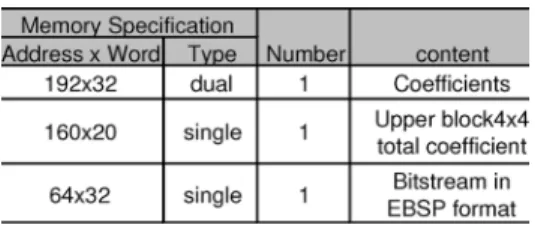
The proposed entropy coding engine with dual-block-pipelined architecture, zero skipping technique, NAL en-capsulation bitstream packer, and a 2-Kb bitstream buffer is implemented by using cell-based design flow and 0.18-UMC/Artisan cell library. Table III shows the gate count profile. To achieve full hardware utilization by the dual-buffer architecture, two block statistic buffers are required. An addi-tional 6000 gates are needed. Table IV shows the local memory requirement. Three types of memories are required. The coef-ficient memory and bitstream memory are used as input and output buffers for system consideration. The upper 4 4 block total coefficient memory is used to story the 4 4 block total coefficients required by following blocks. The entropy coding engine requires about 500 cycles for high-quality applications ( –20) and about 200 cycles for low-bit-rate
applica-tions ( –45).
C. Integration
The basic entropy coding architecture mentioned was first integrated in the H.264 intra coder [10]. It was only designed
for I-frames in standard definition television (SDTV, 720 480 30 fps) format at 54 MHz. The dual-block-pipelined archi-tecture with zero skipping improves the processing capability. It is integrated into an H.264/AVC baseline profile encoder to support high-definition television (HDTV720p, 1280 720 30 fps) format at 100 MHz. In fact, the encoder bottleneck is motion estimation. The entropy coding block is capable of processing 1920 1088 30-fps videos in real time.
V. CONCLUSION
In this brief, a VLSI architecture of the entropy coding for the H.264/AVC baseline profile is designed. We analyzed the fea-tures of CAVLC and proposed the dual-buffer architecture. The scanning of a block and the coding of the previous block are si-multaneously processed in a block pipeline fashion, which dou-bles the hardware utilization and processing throughput at high bit rates. The zero-skipping technique can further skip the re-dundant computations in low-bit-rate situations. In addition, for system considerations, the NAL conversion is integrated in the bitstream packer, and the bitstream buffer is also used to favor the burst transmission via a bus. It can encode 1920 1088 30-fps videos in real time with 23.6 K logic gates at 100 MHz.
REFERENCES
[1] J. V. Team, “Draft ITU-T Recommendation and Final Draft Interna-tional Standard of Joint Video Specification,” , ITU-T Rec. H.264 and ISO/IEC 14496-10 AVC, May 2003.
[2] Information Technology—Coding of Audio-Visual Objects—Part 2:
Vi-sual, ISO/IEC 14496-2, 1999.
[3] Video Coding for Low Bit Rate Communication, ITU-T Rec. H.263, 1998.
[4] Information Technology—Generic Coding of Moving Pictures and
As-sociated Audio Information: Video, ISO/IEC 13818-2 and ITU-T Rec.
H.262, 1996.
[5] A. Joch, F. Kossentini, H. Schwarz, T. Wiegand, and G. J. Sullivan, “Performance comparison of video coding standards using Lagragian coder control,” in Proc. ICIP, 2002, pp. 501–504.
[6] T. Wiegand, G. J. Sullivan, G. Bjøntegaard, and A. Luthra, “Overview of the H.264/AVC video coding standard,” IEEE Trans. Circuits Syst.
Video Technol., vol. 13, no. 7, pp. 560–576, Jul. 2003.
[7] Y. Su and M.-T. Sun, “Fast multiple reference frame motion estimation for H.264,” in Proc. ICME, 2004, pp. 695–698.
[8] Y.-W. Huang, T.-C. Wang, B.-Y. Hsieh, T.-C. Wang, T.-H. Chang, and L.-G. Chen, “Architecture design for deblocking filter in H.264/JVT/ AVC,” in Proc. ICME, 2003, pp. I693–I696.
[9] T.-C. Chen, Y.-W. Huang, and L.-G. Chen, “Fully utilized and reusable architecture for fractional motion estimation of H.264/AVC,” in Proc.
ICASSP, 2004, pp. V9–V12.
[10] Y.-W. Huang, B.-Y. Hsieh, T.-C. Chen, and L.-G. Chen, “Hardware architecture design for H.264/AVC intra frame coder,” in Proc. ISCAS, 2004, pp. II269–II272.
[11] T.-C. Chen, Y.-W. Huang, and L.-G. Chen, “Analysis and design of macroblock pipelining for H.264/AVC VLSI architecture,” in Proc.
ISCAS, 2004, pp. II273–II276.
[12] W. Di, G. Wen, H. Mingzeng, and J. Zhenzhou, “A VLSI architecture design of CAVLC decoder,” in Proc. 5th Int. Conf. ASIC, Oct. 2003, pp. 962–965.
[13] I. Amer, W. Badawy, and G. Jullien, “Towards MPEG-4 part 10 system on chip: a VLSI prototype for context-based adaptive variable length coding (CAVLC),” in Proc. SIPS, Oct. 2004, pp. 275–279.
[14] Joint Video Team Reference Software JM8.5 [Online]. Available: http://bs.hhi.de/suehring/tml/download/ Sep. 2004
[15] S.-M. Lei and M.-T. Sun, “An entropy coding system for digital HDTV applications,” IEEE Trans. Circuits Syst. Video Technol., vol. 1, no. 1, pp. 147–155, Mar. 1991.