Development and Application of the Logical Structures of IEEE Safety
Standards
Kuo-Ting Lien
1, Swu Yih
2, Chin-Feng Fan
1, Wan-Hui Tseng
1, Yi-Chen Wu
1,31
Computer Science and Engineering Dept., Yuan-Ze University, Taiwan
2
Computer Science and Information Dept., Ching-Yun University, Taiwan
3
Center for General Education, Chang Gung University
[email protected]
,
[email protected]
Abstract
-Safety and security are two relevantproperties to software quality. The security area has Common Criteria (CC) for producing and review of security requirement documents. However, the safety area lacks such a standard for users to construct safety documentation. Thus, based on the structures of common criteria, we proposed a logical structure of IEEE 603, a safety standard for nuclear power station. The required items are extracted and represented by CC-like classes, families, and components. Moreover, we used UML diagrams to express the relationship within the logical structures and their components. Based on these proposed components, we developed a method to asses the safety level of the reviewed documentation. Our approach enhances the readability and structures of safety documents and also improves review efficiency.
Keywords: IEEE 603, safety, security, Common
Criteria CC, Requirement documentation.
1. Introduction
Safety and security are both quality characteristics of a software system. Safety means that the executed systems need to be kept in a stable state so that they will not make any damages to people or environments. Security means that the system can prevent illegitimate use and the assets are protected from intentional or accidental operation, such as virus or non-authorized access.
For security, Common Criteria (CC) [5-7] standard is a methodical and structural guideline for users to produce and review the security documents. Common Criteria contains a set of common security components for security functions. Users may select suitable components to use in their documents. CC is a defined structure for both users and reviewers to follow. On the other hand, there are many software-related safety standards, such as DO-178 for Airborne Systems and Equipment, and BTP-14 for Nuclear power plants, etc. These safety standards use a
natural language to describe their requirements. The safety area lacks a CC-like standard for users to construct safety documents. Thus, we proposed to use a CC-like approach to safety systems. Based on the Common Criteria, we developed logical structures for IEEE 603[1], a safety standard for nuclear power stations. The required items are extracted and represented by CC-like classes, families, and components. Then, Unified Modeling Language (UML) diagrams were used to express the relationship within the components of the logic structures. UML provides a visual overview for users to understand the IEEE 603. Finally, a method to asses the safety level of the reviewed documentation was developed. Under our proposed logical structures, safety documents can be easily presented and reviewed.
This paper describes our approach. Section 2 briefly overviews IEEE 603 and Common Criteria. Section 3 presents our proposed logical structures. Section 4 presents a case study. It is followed by conclusions.
2. Related Background
2.1 IEEE 603 Standard
IEEE Std 603[1] and IEEE 7-4.3.2[2] are established by the Safety-Related Systems Working Group of the IEEE Nuclear Power Engineering Committee. IEEE 603 establishes minimum functional design criteria for the power, instrumentation, and control portions of nuclear power generating station safety systems. IEEE Std 7-4.3.2-1993 provides additional guidance on applying the safety system criteria to computers as components in safety systems. IEEE603 contains 8 sections; section 4 and 5 consists of major safety functional requirements. Section 4 addresses safety system design basis, and Section 5 is Safety system criteria. However, both IEEE Std 603 and IEEE 7-4.3.2 use natural languages and do not have a structural format for users to follow.
The Common Criteria [5-7] represents the outcome of a series of efforts to develop criteria for evaluation of IT security. The CC was adopted as ISO/IEC 15408[8] in June, 1999. The CC provides common security requirements for the security functions of IT products and systems, and for assurance measure during a security evaluation. The evaluation results may help consumers to determine whether the IT product or system is secure enough for the intended application and whether the security risks implicit in its use is tolerable
.
The CC defines the structure of Protection Profile (PP) and Security Target (ST). The PP includes the sections as PP introduction, conformance claims, security problem definition, security objectives, extended components definition, and security requirements. CC part 2 and part 3 list all the security functional components and security assurance components.
3. Logical Structures of IEEE 603
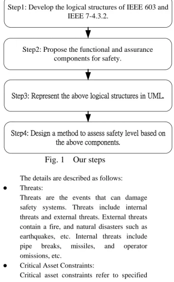
In general, safety critical systems should be reviewed for license before operation so as to ensure the safety of the user and the general public. There are different standards for different safety domains [1-4]. However, these standards lack a clear format for users to follow. On the other hand, the security area provides Common Criteria for producing or evaluating security requirement documents. The Common Criteria provides a series of security functional and assurance classes, families, and components. Thus, we proposed logical structures for safety documents, and also designed safety-related functional and assurance components based on IEEE 603. Then, UML diagrams are used to visually show relationship among the structures and components. A method to assess the safety level achieved is also developed. These steps are shown in Fig 1. Step1: Develop the logical structures of IEEE 603 and IEEE 7-4.3.2.
We proposed that the top level structure should contain the items : (1) Threat, (2) Critical Asset Constraints, (3) Defensive Measures, and (4) Assurance Requirements.
Step1: Develop the logical structures of IEEE 603 and IEEE 7-4.3.2.
Step2: Propose the functional and assurance components for safety.
Step3: Represent the above logical structures in UML.
Step4: Design a method to assess safety level based on the above components.
Fig. 1 Our steps
The details are described as follows:
z Threats:
Threats are the events that can damage safety systems. Threats include internal threats and external threats. External threats contain a fire, and natural disasters such as earthquakes, etc. Internal threats include pipe breaks, missiles, and operator omissions, etc.
z Critical Asset Constraints:
Critical asset constraints refer to specified ranges of safety related variables, such as the safety range of voltage, frequency, radiation, and temperature.
z Defensive Measures:
Defensive measures keep the system in a stable condition so as to prevent the threats from damaging the systems. Defensive measures are classified into two types: (1) functional measures, and (2) structural measures. The functional measures include display, monitor, and testing functions. The structural measures include design techniques for redundancy, and defense-in-depth, etc.
z Assurance Requirements:
Assurance requirements are to ensure the defensive measures are implemented
successfully. We classified them into two types: (1) Performance requirements, and (2) Assessment requirements. The former includes quality assurance and reliability. The latter includes single-failure criteria, identification modules, etc.
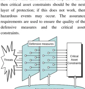
Fig 2 depicts the relationships among these proposed structures. Threats may cause system critical assets to exceed safety ranges, and thus lead the system to an unsafe state. Defensive measures would prevent this from happening. However, when these measures may have flaws, then critical asset constraints should be the next layer of protection; if this does not work, then hazardous events may occur. The assurance requirements are used to ensure the quality of the defensive measures and the critical asset constraints. Assurance requirements Defensive measures Threats Critical Asset Constraints Assurance requirements Defensive measures Threats Critical Asset Constraints
Fig. 2 The relations of main items
Step2: Propose the functional and assurance components for safety.
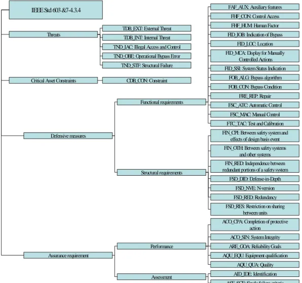
Under the above structures, namely, threat, critical asset constraints, defensive measures and assurance requirement, we identify safety components. Each component belongs to a certain family. Based on the Sections 4 and 5 of IEEE 603, we have identified 5 Threat families, 1 Critical Asset Constraints family, 20 Defensive Measures families and 7 Assurance Requirements families, as well as a total of 85 components. Fig. 3 shows the structure of the entire classes and families. We will show part of these components as below. The rest details can be found in [10].
z Sample components of Threats : TDB: Safety system design basis threats TDB_EXT: External threats
TDB_EXT.1: The earthquake may reduce the system safety.
TDB_EXT.2: The typhoon may
reduce the system safety.
z Sample components of Critical Asset Constraints:
CDB: Safety system design basis constraint CDB_CON: Constraints
CDB_CON.1: The operation mode includes initial state, the limited value of device states.
CDB_CON.2: To identify each control variable constants of protective action. CDB_ CON.3: The safety function can allow manual operation to face any operation environment.
z Sample components of Defensive Measures FHF: Human Failure
FHF_CON: Access Control
FFA_CON.1: the safety system should provide the access control management.
z Sample components of Assurance Requirements
ACO: Completion
ACO_CPA: Completion of protective action ACO_CPA.1: the intended sequence of protective actions of the execute features shall continue until completion.
Different constraints deal with different threats; different defensive measures handle different threats. Table 1 shows part of the relationships between threats and critical asset constraints. Marks in the table entries indicate that the corresponding relationships exist. Similarly, such a table between defensive measures and threats can be constructed. These corresponding relationships help users’ understanding, and also help reviewers’ checking for design completeness/sufficiency.
Table 1. Part of the relationships between threat and critical asset constraints
Threats CDB_CON.1(device limite d CDB_CON.2(control v a riab le) CDB_CON.3(op eration environment) TDB_EXT.1(earthquake) x x TDB_INT.2(channel lose) x x x TND_OBE.1(bypass error) x x x Constraints
Threats
Functional requirements
FAF_AUX: Auxiliary features
TDB_EXT: External Threat
ACO_CPA: Completion of protective action
FHF_CON: Control Access
FSD_RES: Restriction on sharing between units FHF_HUM: Human Factor
FSD_DID: Defense-in-Depth
FSD_RED: Redundancy FSD_NVE: N-version TND_IAC: Illegal Access and Control
FOB_CON: Bypass Condition FOB_ALG: Bypass algorithm FID_MCA: Display for Manually
Controlled Actions FID_SSI: System Status Indication
FID_IOB: Indication of Bypass FID_LOC: Location
FRE_REP: Repair FSC_ATC: Automatic Control
FSC_MAC: Manual Control FTC_TAC: Test and Calibration
Assessment Performance Structural requirements
ARE_GOA: Reliability Goals
AQU_QUA: Quality AQU_EQU: Equipment qualification
FIN_RED: Independence between redundant portions of a safety system FIN_CPI: Between safety system and
effects of design basis event FIN_OTH: Between safety systems
and other systems IEEE Std 603 &7-4.3.4
AID_IDE: Identification ASF_SGF: Single failure criteria Assurance requirement
Critical Asset Constraints
Defensive measures
TDB_INT: Internal Threat
CDB_CON: Constraint TND_OBE: Operational Bypass Error
TND_STF: Structural Failure
ACO_SIN: System Integrity
Fig. 3 The proposed safety classes and families based on IEEE 603 Step3: Represent the above logical structures in
UML.
In order to visually represent the relationship within the above safety components, UML diagrams are drawn. Fig 4 uses a package diagram to show the overview of the top level structures. In the diagram, package Threat and package
Defensive measures have the defensive relation,
package Threat and package Critical Asset
Constraints have the constraint relation, package Assurance requirements and package Defensive measures have the assurance relation, and
package Critical Asset Constraints and package
Assurance requirements have assurance relation.
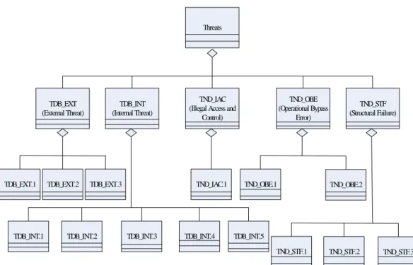
Fig 5 uses a class diagram to show the proposed components under Threat.
Threats TDB_EXT (External Threat) TDB_INT (Internal Threat) TND_IAC (Illegal Access and
Control) TND_OBE (Operational Bypass Error) TND_STF (Structural Failure)
TDB_EXT.1 TDB_EXT.2 TDB_EXT.3
TDB_INT.1 TDB_INT.2 TDB_INT.3 TDB_INT.4 TDB_INT.5
TND_IAC.1 TND_OBE.1 TND_OBE.2
TND_STF.2
TND_STF.1 TND_STF.3
Fig. 5 Components of threats Step 4: Design a method to assess safety level
based on the above components.
We then developed an assessment method judge the safety level of the reviewed system. We proposed the following 4 levels of safety:
z Level 1: Safety systems should satisfy requirements of this level. This level requires the highest safety assurance. All of the proposed 85 components need to be met.
z Level 2: Control systems belong to this level. This level requires all of the components at Level 1, except for the ones related to redundancy design, which include ASF_SGF(Single-failure criteria family), and FSD_DID (N-version family).
z Level 3: Monitoring systems belong to this level. The level requires all of the components at Level 2, except components dealing with completion of protective action, and bypass functions, which include CO_CPA (Completion of protective action), and ACO_SIN (System Integrity ) families.
z Level 4: Data store systems belong to this level. This level requires all of the components at Level 3, except testing related components, which contains FTC_TAC (Test and Calibration) family.
Table 2. Compared these two cases and IEEE 603 components IEEE 603 components Total number of componen ts The number of Project X completed items The number of AP1000 completed items FAF: Auxiliary features 2 0 1 FHF: Human Failure 2 2 2 FID: Information Displays 8 5 8 FIN: Independence 17 6 14 FOB: Operational Bypass 2 2 2 FRE: Repair 1 1 1 FSC: Sense and Command features 6 0 3 FSD: Structure Design 5 1 2 FTC: Test and Calibration 3 2 3 ACO: Completion 3 2 3 AID: Identification 9 1 2 AQU: Quality 21 3 4 ARE: Reliability 3 0 2 ASF: Single-failure criteria 3 3 3 Total 85 28 50
4. Case Study
Two application cases are reviewed according to our proposed IEE 603 components. One case is Project X, and the other is AP1000 [9] in USA. Both are safety systems and should satisfy component requirements at Level 1. Based on their IEEE603 conformance list, the results are given in Table 2. The results indicate that AP1000 is better than Project X since AP1000 addressed 50 components out of the total 85, while Project X only addressed 28. These two cases are both weak in structural design and quality requirements. The Project X is also short at Auxiliary features, Sense and Command features and Reliability requirements.
5. Conclusion
In this paper, we proposed the logical structures for an IEEE safety standard, namely, IEEE 603. These structures can help the power plant construction company to efficiently prepare their safety documents and also help the licensing reviewer to effectively review safety documents. Comparing the original plain text IEEE standard with our structuralized and componentized approach, we conclude that our approach achieves the following advantages:
1. Comprehensibility is enhanced by showing the explicit logical relations among requirements.
2. The logical structures and proposed components make it easy for the power plant constructor to follow and implement.
3. The logical structures and proposed components make it easy for the reviewer to check for the degree of standard conformance. 4. Our approach supports reusability.
In the future, we will develop an editing tool and a review tool to help both the developer and the reviewer.
Acknowledgement
This work was supported in part by National Science Council grant no. NSC 96-2221-E-155-047.
References
[1] Nuclear Power Engineering Committee of the IEEE Power Engineering Society, “IEEE Standard Criteria for Safety Systems for Nuclear Power Generating Stations” July 1, 1998.
[2] Nuclear Power Engineering Committee of the IEEE Power Engineering Society, “IEEE Standard Criteria for Digital Computer in Safety Systems for Nuclear Power Generating Stations” July 1, 1998.
[3] U.S. Food and Drug Administration, “General Principles of Software Validation; Final Guidance for Industry and FDA Staff”, January 11, 2002.
[4] U.S. Food and Drug Administration, “Guidance for Industry and FDA Staff, Guidance for the Content of Premarket Submissions for Software Contained in Medical Devices”, May 11, 2005.
[5] Common Criteria, “Common Criteria for information Technology Security Evaluation - Part 1: Introduction and general model, Version 3.1”, September, 2006.
[6] Common Criteria, “Common Criteria for information Technology Security Evaluation - Part 2: Security functional components, Version 3.1”, September, 2007.
[7] Common Criteria, “Common Criteria for information Technology Security Evaluation - Part 3: Security assurance components l, Version 3.1”, September, 2007.
[8] International Standard ISO/IEC 15408, Information technology – Security techniques - Evaluation criteria for IT security.
[9] Westinghouse, “603 NRC Review Question, Attachment 1”, November 30, 2005.
[10] Kuo-Ting Lien, “Development and Application of the Logical Structures of Safety-critical software standards,” M.S. Thesis, Computer Science and Engineering, Yuan-Ze University, Taiwan. (in Chinese)