Design Space Exploration and Construction of an
Arbiter Design Model
Jer Min Jou1, Yun-Lung Lee1, Ren-Der Chen2, Sih-Sian Wu1, Cheng Chou3, and Yen-Yu Chen1
Department of 1EE and 3CSIE, National Cheng Kung University, Tainan Department of 2CSIE, National Changhua University of Education, Changhua
Taiwan, R.O.C.
E-mail: Prof. Jer Min Jou (周哲民), jou@j92a21.ee.ncku.edu.tw
Abstract — Because of the flourish of multi-processor
system-on-a-chips (MPSoCs) and on- or off-chip high-speed networks, how to design an efficient arbiter, although a classical problem, now becomes more and more important. In the past, there were little or no work that thoroughly discussed the functionality, design issues and models of arbiters, which resulted in the inferior arbiter design and usages. Here, we have aimed at exploring the design space and the issues of operating of arbiters, and proposed a new multi-function arbiter design model and classification. With this new design model, we could further know the required key points of arbiter design, and thus have designed an efficient integrated multi-function arbiter that suitable to many
different applications. A Round-Robin arbiter based on
this model has been designed; to best of our knowledge, it is the fastest and smallest Round-Robin arbiter.
Index Terms — Multi-function arbiter, design space,
design model, round-robin, granularity, arbitrating latency, waiting latency.
I. INTRODUCTION
With the rapid evolution of technology, the complexity has become one of the most constraining aspects in the design and implementation of embedded multi-processor system-on-a-chips (MPSoCs) [1], where many IPs (Intellectual Property) such as processor cores, memories, DSP processors, and peripheral devices are integrated on a single die. These IPs are shared one another in order to integrate and operate efficiently as well as to reduce the system
area and cost. One of the important issues in MPSoC design is to increase the computation and/or communication performance among sharing IPs. Therefore, the high-speed and low-cost arbiters with efficient sharing arbitration among them become critical.
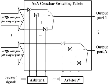
As far as the efficiency is concerned, the notable sharing communication resource in an MPSoC is the shared on-chip switches, which are shared by some or all of the computation elements. Fig. 1 shows such an on-chip switch connected with some IPs, which are treated as its input or output masters by the I/O ports. If it is necessary to transmit data between the input and output masters, a request signal will be sent by the input master to request the use authority of the on-chip switch. Then these request signals will be arbitrated by the arbiter and one of the masters will be granted to monopolize the shared bus. As the number of masters increases in a single chip like many cores MPSoCs with thousand of cores [4], the resource contention will increase quickly, then the performance and fairness of the arbiters dealing with the serious resource contentions need more attention [1].
Many arbiter designs have been proposed [2] [3] [5], but they did not analyze and explore the arbiter design space thoroughly, and failed to achieve the arbiters’ high performance and/or
design simplicity. Here, we focus on exploring the design space and issues of arbiter operations, and then propose a new arbiter design model and classification. With this new design model, we have already designed many new multi-function arbiters with a high arbitration performance and/or a less area. A Round-Robin arbiter based on the proposed design model has been designed; to best of our knowledge, it is one of the fastest and smallest Round-Robin arbiters in the world.
... ... ... ... … Output port 1 Output port N N×N Crossbar Switching Fabric
...
…
VOQs compete for output port 1
VOQs compete for output port N
…
Arbiter N Arbiter 1
request signals
Fig. 1. An n×n switch: block diagram, crossbar switch fabric and its switch arbiters.
This paper is organized as follows: Section II describes the background of the arbiter. Section III illustrates some issues about the arbiter design, and the corresponding solutions will be provided in Section IV. Section V describes the new arbiter design model, and the simulation results of our arbiters compared with other existing ones are shown in Section VI. Finally, conclusions will be made in Section VII.
II. BACKGROUND
When a monopolized-only resource is shared by N masters, every unit of usage time of the resource (described as time unit below) can be allocated to only one master. Therefore, if there
are many masters requesting a monopolized use of the resource at the same time, an arbitration scheme is needed to determine which one has the usage authority of each time unit fairly and efficiently. The time on which the arbiter has serviced every master with a request is defined as an arbitration round. It is determined by the number of masters who request the resource simultaneously, but does not exceed N time units.
When an arbiter works, not only the request signals provided by each master but also some other information must be considered by it, and those important information about arbitration includes: 1) Bandwidth (BW) request ratio of the masters: For example, if the BW request ratio of three masters are 3:2:1, then the number of 3 indicates that the bandwidth request quantity of the first master is 3 time units of the resource usage. 2) Waiting latency of each master: This time is defined as the number of time units that the master waits for the arbiter’s grant. 3) Resource
granularity: It indicates the maximum number of
data unit that a granted master could obtain from the shared resource per time unit. The data unit is defined as the basic unit of the quantum or bandwidth that the shared resource could provide. 4) Arbitrating latency: It indicates the total number of time units (or arbitrations) required by the arbiter to arbitrate a master request. In other words, the arbitrating latency of the arbiter could be defined as the total time units between a master request is first granted to the time the request is fulfilled and finished. 5) Priority of each master: It determines various authorities among different masters. Under various arbitration schemes, it brings about some arbitration interrupting behavior choices: 6) Preemption or 7)
Non-preemption.
III. DESIGN ISSUES OF ARBITERS
explored and four important design issues of arbiters are also discussed.
A. Issue about the BW request quantity and
waiting latency tradeoff
The masters which request the same resource at the same time are usually arbitrated by a conventional arbiter based on the values of their
BW request quantities, and the master with the
largest value is granted first. The waiting latency of each master is, therefore, dependent on the corresponding BW request quantity. A master with smaller BW request quantity always has larger waiting latency, and even starvation may occur among masters. Shown in Fig. 2(a) is the request schedule for three masters M1, M2, and
M3 with BW request quantities 6, 3, and 1,
respectively, and Mi on the time axis indicates
that the request of Mi is issued at that time. The
corresponding resource schedule, given in Fig. 2(b), is arbitrated according to the BW request
quantities of the masters. We can see that these
three masters issue their requests simultaneously at time 1 and 11, and M1 gets granted earlier than
both M2 and M3 due to its larger BW request quantity. However, if M2 or M3 needs less
waiting latencies for some reason, this arbitration scheme depending only on the BW request
quantities of the masters no longer works,
although BW request quantity-based arbitration is often r
B. Issue about the resource granularity and
arbitrating latency tradeoff
Both the arbitrating latency of masters and resource utilization will be influenced by the resource granularity. Conventionally, the arbitration fairness of most arbiters is reserved by servicing each master in a round-robin manner for each arbitration round. In other words, each master gains at most one access to the shared resource in each arbitration round. The round-robin arbitration scheme is adopted by many arbiters because of its simplicity and starvation-freeness. However, there is a tight-coupled relation between resource granularity and arbitrating latency for the round-robin arbiters. The arbitrating latencies are hence smaller for masters using coarse-grain resource granularity, but this scheme may result in severe resource over-allocation problem. For example, masters M1, M2, and M3 requesting
three data units of shared resource simultaneously, the resource schedule results (RSRs) based on 2 and 1 data units of resource granularity are shown in Fig. 3(a) and (b), respectively. The arbitrating latency of M1 (four time units) in Fig. 3(a) is
smaller than the one (seven time units) in Fig. 3(b). The arbitrating latencies can hence be efficiently reduced for arbiters with coarse-grain resource granularity. However, this coarser resource granularity will make the resource over-allocation problem, e.g., each of the three masters in Fig. 3(a) wastes one time unit at time 4, 5, and 6. Therefore, how to tradeoff between arbitrating latency and resource utilization has become an important issue.
easonable and good.
… 2 1 3 4 5 6 7 8 9 10 11 12 13 14 15 Request Schedule [ time unit ] M1 M2 M3 M1 M1 M2 M1 M2 M1 M1 M1 M2 M3 M1 M1 M2 (a) Resource Schedule [ time unit ] M1 M1 M1 M2 M1 M1 … 2 1 3 4 5 6 7 8 M2 M1 M2 M3 M1 M1 9 10 11 12 Resource schedule [ data unit ] [ time unit ] M1 M1 M1 MM33 … 2 1 3 4 5 6 M2 M2 M2 M3
Granularity = 2 data unit
2
1 3 4 5 6 7 8 9 10 11 12
(b)
Fig. 2. (a) Request schedule for masters M1, M2 and
M1 M2 M3 M2 M3 M1 … 2
1 3 4 5 6 7 8
M1 M2 M3
9 10
Granularity = 1 data unit
2 1 3 4 5 6 7 8 9 10 Resource schedule [ data unit ] [ time unit ] (b)
Fig. 3. (a) The RSR with resource granularity = 2. (b) The RSR with resource granularity = 1.
C. Issue about the resource granularity and
fairness tradeoff
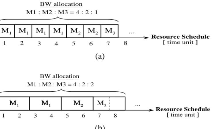
The arbitration fairness can be influenced by the resource granularity. An arbiter is fair if (1) it is work-conserving; i.e., it never leaves any resource idle if there are requesting masters, and (2) it arbitrates resource time units to masters in exactly proportional to their BW request ratio. Using finer resource granularity can provide more precise bandwidth allocation and makes arbitration fairer. For three masters M1, M2, and
M3 with BW request quantities 4, 2, and 1,
respectively, the RSRs corresponding to resource granularities 1 and 2 are shown in Fig. 4(a) and (b), respectively. In Fig. 4(b), the arbiter wastes one time unit at time 8 since the resource granularity is larger than its request data unit.
M1 M1 M1 M2 M2 M3 … 2 1 3 4 5 6 7 8 M1 BW allocation M1 : M2 : M3 = 4 : 2 : 1 Resource Schedule [ time unit ] (a) 2 1 M1 M1 … 3 4 5 6 M1 M1 MM22 7 8 M3 BW allocation M1 : M2 : M3 = 4 : 2 : 2 Resource Schedule [ time unit ] (b)
Fig. 4. (a) The RSR with resource granularity = 1. (b) The RSR with resource granularity = 2.
D. Issue about the integrity of arbiter design
Conventional arbiters are usually designed for a single arbitration object, so the multiple
same time. For instance, a round-robin arbiter cannot continuously provide smaller waiting latency to the emergent masters; the linear-priority arbiter does not provide both preemptive and non-preemptive arbitration behaviors; the waiting-latency-aware arbiters give higher priories to masters with stricter waiting latency requirement but lower priorities to the others. The reason is that they cannot be designed in an integrated and modular manner because of the lack of a comprehensive arbiter design model.
IV. SOLUTIONS TO THE DESIGN ISSUES OF
ARBITERS
To solve the problems about arbiter design described in the previous section, the design space is explored here and the solution to each design issue is also proposed.
A. Solution about the issue about BW request
ratio and waiting latency tradeoff
To deal with the issue of BW request ratio and waiting latency tradeoff, the following solution is proposed. Since it is not appropriate to arbitrate the masters, which have different waiting latency requirements, based only on their BW request quantities, an additional parameter accompanied with each master, called the priority, is added. This parameter is used to arbitrate the masters under the BW request ratio constraint. The masters that have smaller waiting latency requirements are usually assigned higher priorities, and the arbitration is made according to their priorities and BW request ratio. The priority value of each master can be assigned statically or dynamically. It is defined as a positive integer pi
for master Mi, where pi=1 indicates the highest
priority. This priority-based BW request ratio arbitration can be further classified into
arbitration, which can then be implemented as a BW request ratio-based linear-priority arbiter and a round-robin arbiter, respectively.
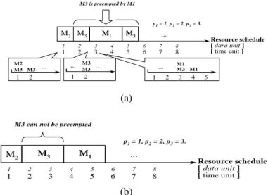
There are two types of non-equal-priority arbitration: preemption and non-preemption. Preemption non-equal-priority arbitration allows the higher-priority master to interrupt and preempt the resource of the lower-priority master. Preemption arbitration guarantees that higher-priority masters will have smaller waiting latency than lower-priority ones. This makes the waiting latency of a master inversely proportional to its priority value; i.e., the waiting latency of the highest-priority master is the smallest. Fig. 5(a) shows an example of preemption arbitration. At time 2, the arbiter grants M3 to access the shared
resource for two time units, and then the highest priority master M1 requests at time 3. At this time,
the granted shared resource of M3 will be
preempted by M1. In contrast to the preemption,
the non-preemption arbitration does not allow any master to be interrupted as they are using the shared resource. The higher-priority master has to wait for the lower-priority master to finish its shared resource usage continuously. The RSR of the non-preemption arbitration is shown in Fig. 5(b), where the highest-priority master M1 has to
wait for the completion of M3 using the shared
resource. Compared with the preemption arbitration, the arbitrating latencies of lower-priority masters can be decreased in a non-preemption arbitration, but the waiting latency of higher-priority masters will be increased. This results in a tradeoff between the waiting latency and arbitrating latency of a master. M2 M3 MM11 MM33 … 2 1 3 4 5 6 7 8 2 1 3 4 5 6 7 8 M3 is preempted by M1 Resource schedule [ dara unit ] [ time unit ] 2 1 M2 M3 M3 p1= 1, p2= 2, p3= 3. 2 1 3 4 5 M1 M3 M1 … … 2 1 M3 … M3 … (a) M2 MM33 … 2 1 3 4 5 6 7 8 2 1 3 4 5 6 7 8
M3 can not be preempted
M1 M1 Resource schedule [ data unit ] [ time unit ] p1= 1, p2= 2, p3= 3. (b)
Fig. 5. (a) Preemption arbitration. (b) Non-preemption arbitration.
B. Solution to the issue about resource
granularity and arbitrating latency tradeoff
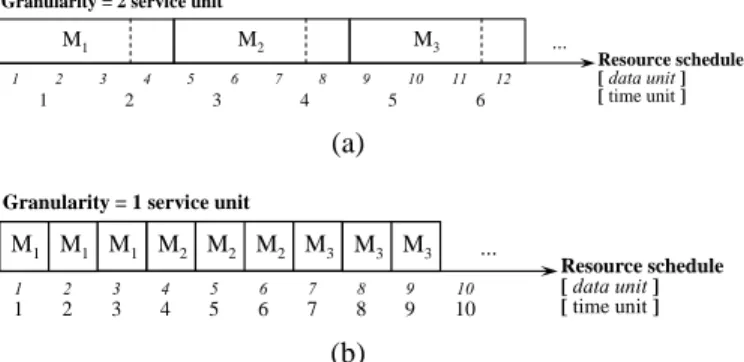
The solution to solve the couple between resource granularity and arbitrating latency is proposed here. Since some arbitration algorithms may satisfy portions of the requirements of masters in each arbitration round like “installment”, they suffer a situation in which the arbiter needs many arbitration rounds to satisfy masters with large amount of requirements and increases their arbitrating latencies. To deal with this problem, the non-preemption scheme is adopted to arbitrate a shared resource to one master non-preemptedly, and then its resource granularity and arbitrating latency are decoupled. Like the same conditions in Fig. 3(a) and (b), Fig. 6(a) and (b) show the RSRs of non-preemption. The arbitrating latencies of all masters are minimized and equal to their request values, and the waiting latencies are growing inversely with their priority values. To avoid the starvation caused by non-preemption, a bandwidth-weight tuning scheme could be used to regulate and to limit the bandwidth gained by the masters.
M1 … Granularity = 2 service unit
2 1 3 4 5 6 2 1 3 4 5 6 7 8 9 10 11 12 M2 M3 Resource schedule [ data unit ] [ time unit ] (a) M1 M1 M1 M2 M2 M2 M3 M3 M3 …
Granularity = 1 service unit
2 1 3 4 5 6 7 8 9 10 2 1 3 4 5 6 7 8 9 10 Resource schedule [ data unit ] [ time unit ] (b)
Fig. 6. (a) The waiting latency of Fig. 3(a) is reduced by non-preemption. (b) The waiting latency of Fig. 3(b) is reduced by non-preemption.
C. Solution to the issue about resource
granularity and fairness tradeoff
The relation between resource granularity and arbitrating latency can be decoupled by the non-preemption design, so the finest resource granularity is adopted for shared resource to increase resource utilization and to keep fairness. For fairness, a set of integers is used to represent the BW request ratio of masters. Then a master isolation scheme is applied to protect the bandwidth of each master from being robbed by other masters. The concept of master isolation is described as follows. In a fixed amount of time, we give each master some time units called BW
quota according to its BW request quantity. Every
time when a shared resource is used by a master, its BW quota is decreased. When a master uses up its BW quota, its following requests will be ignored by the arbiter to prevent the bandwidth of other masters from being robbed.
D. Solution to the issue about integrity
The proposed reconfigurable and modular concept will be applied to design an arbiter to fulfill versatile arbitration schemes. The modular and reconfigurable arbiter can be reconfigured modularly as a linear-priority arbiter with a preemption or non-preemption mechanism to
favor higher-priority masters and lower-priority masters with low waiting latency and low arbitrating latency, respectively.On the other side, the modular arbiter can be reconfigured as an equal-priority arbiter like a round-robin arbiter to prevent masters from starvation. Moreover, the master isolation idea can also be implemented to maintain the fairness between masters.
From the solutions described above, an arbiter with complete arbitration schemes should have the following essential input parameters: request signal, priority, BW request quantity or BW request ratio, and the choice of preemption or non-preemption. Based on these arbitration parameters, we have developed an arbiter design model in the next section.
V. DEVELOPMENT OF THE NEW MULTI-FUNCTION
ARBITER DESIGN MODEL
After the discussions and analyses of arbiter issues, arbitration factors, and their solutions described above, the design space exploration and development of a new arbiter design model with multi-function are described in detail as follows.
A. Design space exploration of the arbiter design
model
Design space exploration of the arbiter design model involves exploring alternate arbiter configurations to form an efficient design model with some essential factors about the arbiters. Based on the arbiter design solutions above, we find that three essential factors of arbitration are priority, preemption, and bandwidth. These factors will be explored to derive and to build the multi-function arbiter design model. But, how many configurations of those essential factors (and their inverses) does the design space of the multi-function arbiter design model have? How many valid arbiter designs among the configurations do the model and the space have?
What is the processing order of these essential factors in the multi-function design model for design of any valid configurations of the arbiters? As far as the design space is concerned, very essential factor will make the arbiter having the corresponding different arbitrating property. The design space of a multi-function arbiter with some or all of those factors or their inverses may be wide, so an exact design model has to be explored.
Let us assume that the three essential factors
priority, preemption and bandwidth are labeled as
Ω, Φ and Ψ, respectively, and they also indicate that the arbiters will be realized with
equal-priority, preemptive and bandwidth-constraint properties, respectively. On
the other hand, label Ω’, Φ’ and Ψ’ indicates that the arbiter will be realized with non-equal-priority, non-preemptive and no bandwidth-constraint properties, respectively. For example, an arbiter with Ω, Φ’, and Ψ’ properties indicates that it is an arbiter with the equal-priority, (then) non-preemption and (finally) non- bandwidth-constraint properties (circuit modules). Note that the connection order of those factors is also important; the hardware structure of the ΩΦ’Ψ’ arbiter in the design model and the design space has a priority control circuit module connected to a non-preemption module, and then followed by a bandwidth constraint control module. Thus, the design space of an arbiter design model with/without those three essential factors and their inverses has at most 79 different configurations (combinations), and each configuration may or may not form a valid arbiter. For arbiters designed with zero, one, two, and three essential factors, they will form four different sets of valid or invalid configurations of the arbiter: S0, S1, S2, and S3 in the following,
respectively. The whole design space S of the arbiters is the union of set S0, S1, S2, and S3, and
then 79 configurations will correspond to possibly
79 different arbiters. S0 = { }. S1 = {Ω, Φ, Ψ, Ω’, Φ’, Ψ’}. S2 = {ΩΦ, ΦΩ, Ω’Φ, ΦΩ’, ΩΦ’, Φ’Ω, Ω’Φ’, Φ’Ω’, ΩΨ, ΨΩ, Ω’Ψ, ΨΩ’, ΨΩ’, Ψ’Ω, Ω’Ψ’, Ψ’Ω’, ΦΨ, ΨΦ, Φ’Ψ, ΨΦ’, ΦΨ’, Ψ’Φ, Φ’Ψ’, Ψ’Φ’}. S3 = {ΩΦΨ, ΩΨΦ, ΦΩΨ, ΦΨΩ, ΨΩΦ, ΨΦΩ, Ω’ΦΨ, Ω’ΨΦ, ΦΩ’Ψ, ΦΨΩ’, ΨΩ’Φ, ΨΦΩ’, ΩΦ’Ψ, ΩΨΦ’, Φ’ΩΨ, Φ’ΨΩ, ΨΩΦ’, ΨΦ’Ω, ΩΦΨ’, ΩΨ’Φ, ΦΩΨ’, ΦΨ’Ω, Ψ’ΩΦ, Ψ’ΦΩ, Ω’Φ’Ψ, Ω’ΨΦ’, Φ’Ω’Ψ, Φ’ΨΩ’, ΨΩ’Φ’, ΨΦ’Ω’, Ω’ΦΨ’, Ω’Ψ’Φ, ΦΩ’Ψ’, ΦΨ’Ω’, Ψ’Ω’Φ, Ψ’ΦΩ’, ΩΦ’Ψ’, ΩΨ’Φ’, Φ’ΩΨ’, Φ’Ψ’Ω, Ψ’ΩΦ’, Ψ’Φ’Ω, Ω’Φ’Ψ’, Ω’Ψ’Φ’, Φ’Ω’Ψ’, Φ’Ψ’Ω’, Ψ’Ω’Φ’, Ψ’Φ’Ω’}. S = S0 ∪ S1 ∪ S2 ∪ S3
For these 79 configurations or possible arbiters, however, some of which are invalid (not an arbiter) and should be removed to prune the design space. The final pruned design space is then used to derive and form the proposed arbiter design model.
In the space, the priority factor determines what types of the priority-based arbitration which an arbiter uses, and an arbiter in nature must have at least one priority-based arbitrating scheme to handle the situation in which many masters compete for a single resource. Thus, no matter which choices we take, the priority factor always has an effect on the arbitration. The priority factor Ω must hence exist in the design space and then in the arbiter model. Therefore, the configurations which do not contain Ω (or Ω’) are removed from the design space. The number of configurations
remained in the space is now 65.
From the definitions of preemption [6], the preemptive arbitration occurs only when masters have different priority levels, called non-equal priority arbitration. Thus, the preemption factor Φ belongs to the sub-option under the non-equal priority arbitration controlled by the priority factor. Another option of the priority factor is the equal-priority arbitration which cannot go with the preemption arbitration since there is no difference among priorities of all masters. In other words, the preemption arbitration only occurs when the arbiter has the non-equal-priority arbitrating property, which is an option determined by the priority factor. Thus, the processing order in the design model is first the priority factor and then the preemption factor. It indicates that Φ must occur in the configurations which contain Ω’ and at the right side of Ω’, and does not occur in the configurations which contain Ω. Therefore, configurations such as Ω’Ψ, ΦΩ’ and ΩΦ are seen as invalid configurations. The design space S is then reduced and only 22 configurations remain in S.
In terms of the shared resource arbitration, priority and bandwidth factors are responsible for granting resource usage orders and granting resource usage times, respectively. The priority factor decides the granting sequence of masters as two or more masters request the shared resource simultaneously, and the bandwidth factor Ψ affects the percentage of bandwidth of shared resource each master gets. Thus they are independent of each other and orthogonal in the design space. What is the processing order between the priority factor and bandwidth factor? From the view of a left-to-right, i.e. leaves-to-root, tree-like classification, and the priority factor is more necessary than the bandwidth factor, we let the priority factor closer to the option at the inner
(right or root) side of the design mode (space). Thus, it is better to let the bandwidth factor locate at the outside (or the left-side) of the arbiter design model. From the arbitration option at the outer side (or the left-side), it classifies the model into two main types. One of them contains arbiters without BW-constraint, and the other one contains arbiters with BW-constraint. Therefore, it is better for Ψ to be located at the left side of Ω in the design space, and configurations such as ΩΨ, Ω’Ψ, … , and ΩΨ’ are eliminated. The number of elements remained in the space is become 27.
Moreover, since the bandwidth factor indicates whether an arbiter is able to do bandwidth- constraint arbitration. The configurations which do not contain Ψ are the same as the ones with Ψ’. In other words, Ψ is also necessary in the options of the configurations. Thus, any configurations not containing factor Ψ (Ψ or Ψ’) should be seen as an invalid configuration. The number of them is 10. The final number of the valid configurations in set S for multi-function arbiter design space is reduced to 6; that is S = { ΨΩ, Ψ’Ω, ΨΩ’Φ, ΨΩ’Φ’, Ψ’Ω’Φ, Ψ’Ω’Φ’}.
B. Development of the multi-function arbiter design model
Based on the fine pruned design space explored above, the proposed arbiter design model will now be derived. The processing order of the three essential factors in the space is as follows: bandwidth Ψ, priority Ω, and then preemption Φ, which will be the order in the design model. Each of them is then an option considered from the right side to the left side in the arbiter design model to be developed.
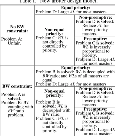
With these six configurations representing six different arbiters, the proposed arbiter design model is then formed and given in Table I. With
the concept of the top-down design methodology, we classify the arbiter design into six types from the outer side to the inner side in the arbiter design model (i.e., from left to right in Table I): non-BW-constraint and equal-priority arbitration, non-BW-constraint and non-equal-priority arbitration without/with preemption, BW- constraint and equal-priority arbitration, BW-constraint and non-equal-priority arbitration without/with preemption, which correspond to the valid configurations (arbiters) Ψ’Ω, Ψ’Ω’Φ’, Ψ’Ω’Φ, ΨΩ, ΨΩ’Φ’, and ΨΩ’Φ in set S, respectively.
Table I. New arbiter design model. Equal priority: Problem D: Large AL for most masters
Non-preemptive: Problem D is solved: Reduce AL for lower-priority masters. No BW constraint: Problem A: Unfair. Non-equal priority: Problem C: WL is not directly controlled by priority. Preemptive: Problem C is solved: WL is inversely proportional to priority. Problem D: Large AL for most masters Equal priority:
Problem B is solved: WL is decoupled with BW ratio; and WLs of all masters are equal
Problem D: Large AL for most masters Non-preemptive: Problem D is solved: Reduce AL for lower-priority masters. BW constraint: Problem A is solved. Problem B: WL coupling with BW ratio problem. Non-equal priority: Problem B is solved: WL is decoupled with BW ratio. Problem C: WL is not directly controlled by priority. Preemptive: Problem C is solved: WL is inversely proportional to priority. Problem D: Large AL for most masters
WL: waiting latency, AL: arbitrating latency.
The model of Table I first divides the arbiter design into two directions, without BW constraint and with BW constraint, depending on one of two orthogonal factors, BW request quantity, that represents whether masters have essential bandwidth requirements. There are two problems
for arbitration without BW constraint, Problem A: Unfair, and Problem B: Waiting latency, WL, couples the BW request quantity. Problem A can be solved by the left-bottom part of Table I depicted as “Solution A is solved”, and Problem B is solved by another facter, priority Ω, which is at the second column of Table I, depicted as “Solution B is solved”. Moreover, there is a problem in non-equal-priority arbitration, depicted as Problem C: Does the waiting latency of a master grows inversely proportional to its priority? In other words, can we control waiting latencies of the masters just by regulating their priorities? This problem can be solved by the “Problem C is solved” at the third column of Table I. However, preemption leads to the high arbitrating latency as shown in Fig. 5(a). This problem can be alleviated by the non-preemption arbitration with “Problem D is solved”, using the non-preemption scheme to trade off the waiting latency and the arbitrating latency of a master.
With this model, the efficient architectures and algorithms of the hardware of the arbiters had been designed and implemented; we omit them due to space limit, but some of design results are given in the next section.
VI. EXPERIMENTAL AND DESIGN RESULTS
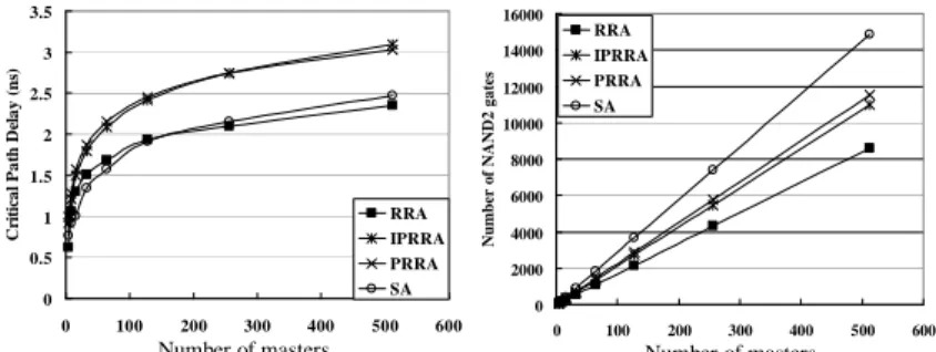
The results of round-robin arbiters, RRAs, designed with the proposed new arbiter design model, Ψ’Ω, are compared with other existing arbiters: SA[2], PRRA[3], and IPRRA[3]. SA[2] is the existing fastest round-robin arbiter, and IPRRA[3] is the existing smallest round-robin arbiter. All the designs are described in Verilog and synthesized under the same typical operating condition using Synopsys Design Vision (2007.03-sp3) targeting the same TSMC 0.18μm standard cell library. Fig. 7(a) and (b) show the critical path delay and area cost of arbiters, respectively. From these figures, we can see that
our arbiter, RRA, outperforms the others at both parts. To the best of our knowledge, our round-robin arbiter is one of the fastest and smallest round-robin arbiters in the world.
Other arbiters with different functions have also been designed, and the results are given in Fig. 8. However, the comparisons about them could not be done here since no corresponding arbiters from other work or the literature have been found until now.
0 0.5 1 1.5 2 2.5 3 3.5 0 100 200 300 400 500 600 Scale C ri ti cal P a th D el ay ( n s) RRA IPRRA PRRA SA 0 2000 4000 6000 8000 10000 12000 14000 16000 0 100 200 300 400 500 600 Scale Nu mbe r o f NAND2 gat es RRA IPRRA PRRA SA
Fig. 7. Comparison of the arbiters in (a) critical path delay and (b) area cost.
Fig. 8. Design results of the multi-function arbiters. VII. CONCLUSIONS
In this paper, a new multi-function arbiter design model which decouples an arbiter’s input parameters and the arbitration output grants has been explored and proposed. This model covers a large design space and solves the arbitration
issues for designing a multi-function arbiter. These issues include the couples and tradeoffs between BW request ratio and waiting latency, between resource granularity and arbitrating
latency or fairness, and finally, the issue about
integrity of the arbiter functions. With this multi-function arbiter design model, the key points required for an arbiter design can be further obtained, and then a more appropriate and simpler arbiter suitable for various applications can be developed. It can be seen from the arbiter design results that the round-robin arbiters designed with the proposed model are fastest and smallest. In the future, the development of the multi-resources and multiple outputs model is one of our next targets.
REFERENCES
Number of masters Number of masters
[1] B. D. Theelen, A. C. Verschueren, Reyes, M. P. J. Stevens, A. Nunez, “A scalable single-chip multi-processor architecture with on-chip RTOS kernel,” Journal of Systems
Architecture, Vol. 49, No. 12, 2003, pp.
619-639. 0 0.4 0.8 1.2 1.6 2 2.4 2.8 3.2 3.6 0 100 200 300 400 500 600 Number of masters C rit ica l p a th d ela y ( n s) Ψ'Ω Ψ'Ω'Φ' Ψ'Ω'Φ ΨΩ ΨΩ'Φ' ΨΩ'Φ
[2] E. S. Shin, V. J. Mooney, and G. F. Riley, “Round-Robin Arbiter Design and Generation,” Proc. Int. Symp. Sys. Syn. (ISSS), pp. 243-248, 2002.
[3] S. Q. Zhengy and Mei Yang, “Algorithm- Hardware Codesign of Fast Parallel Round-Robin Arbiters”, IEEE transactions on
parallel and distributed systems, Vol. 18, No.
1, pp.84-95, Jan., 2007.
[4] S. Borkar, "Thousand Core Chips -- A Technology Perspective," Proc. ACM/IEEE
44th Design Automation Conf., ACM Press,
2007, pp. 746-749.
[5] Yun-Long Lee, Jer Min Jou, Yen-Yu Chen, and Guan-Shiue Wu, “An Optimal Arbiter Design for NoC”, Proceedings of the 2008 International Computer Symposium, 2008. [6] http://en.wikipedia.org/wiki/Preemptive_mult