Based on an Omnidirectional Vision Sensor
Huei-Yung Lin1*, Ming-Liang Wang2, and Chi-Chang Huang3
Department of Electrical Engineering National Chung Cheng University
Chia-Yi 621, Taiwan, R.O.C.
1
[email protected], [email protected], [email protected]
Received 30 August 2008; Revised 15 September2008; Accepted 20 September 2008
Abstract. Visual surveillance, object tracking and activity monitoring are some of the important issues for homecare systems. In this work, an omnidirectional video camera is adopted to provide a 360 degree view angle of the indoor scene with a single image sequence. Some basic functions for smart living and elderly care, such as motion detection, object tracking and target behavior analysis, are implemented. For the motion detection, a foreground object model is first detected and the CamShift algorithm is used for object tracking by extracting color information of the target. To make the motion detection and object tracking fully auto-matic and robust under different illumination conditions, an optical flow approach is cooperated to detect small changes of the mobile object. In addition, the camera is calibrated to obtain the one-to-one correspon-dences between the image pixels and the locations on the ground. The information is then combined with the object model for fall detection and abnormal behavior analysis. Experimental results are presented for the real scene images.
Keywords: motion analysis, object tracking, omnidirectional surveillance
1 Introduction
Detection, localization, and tracking of moving objects such as people or vehicles are key components for many applications including public surveillance, home monitoring, and elderly care [17]. The fundamental capabilities of a visual surveillance system aim to provide recognition and the trajectories of moving objects in the scene, and use them for further processing, for example, decision making or proper reaction given by the system ad-ministrator. In the past few decades, vision-based surveillance has been extensively applied on industrial inspec-tion, traffic control, security systems, and medical and scientific research [1-3]. Most of the applications either require significant manual assistance or have to be performed under controlled environments, especially for the proper illumination condition.
Recently, due to the availability of inexpensive imaging hardware and high demand of home and public monitoring for nursing care or security purposes, visual surveillance has become one of the most important re-search topics in computer and robot vision systems [4]. Commonly implemented approaches include using fixed CCTV (closed circuit television) cameras for traffic monitoring and public surveillance, and using PTZ (Pan/Tilt/Zoom) cameras for flexible installation and specific applications. The major purpose of the PTZ capa-bilities is to increase the field of view of a fixed camera and thus reduce the number of cameras required for surveillance. However, there always exist blind spots caused by the restricted rotation and tilt angles, and the slow motion of the PTZ mechanism. In addition, unsupervised video surveillance is usually not possible without manual scene selection in most situations.
In this work, an omnidirectional video camera [18], [20] is adopted to provide a 360° view angle of the indoor scene in a single image. The vision systems equipped with omnidirectional sensors have been extensively used for mobile robot localization and navigation [5]. Different from image acquisition on a mobile platform, our camera is mounted on the ceiling of the indoor space to provide global surveillance of the environment. As a part of homecare surveillance system design, the omnidirectional video camera is not only responsible for real-time image acquisition used in the nursing and homecare systems. Some basic functions for smart living and elderly care, such as motion detection [15], people tracking and human activity analysis, are also important fac-tors of the system design requirements. For motion detection and people tracking, we propose a method based
* Correspondence author
on MHI (motion history image), CamShift (Continuously Adaptive Mean Shift) [6] and optical flow [7], to in-crease the robustness of the surveillance and tracking system. As for the human activity recognition [8], we present a fall detection method [19] for elderly care using a calibrated one-to-one correspondence between the ground locations and the ODVS (omni-directional vision sensor) images, combined with the trajectory of the tracked target.
The paper is organized as follows. Section 2 describes the experimental setup of the homecare surveillance system and camera calibration of the ODVS [16]. In Section 3, we present the theoretic background of the track-ing algorithms adopted in this work, followed by the proposed method for robust omnidirectional visual tracktrack-ing. In Section 4, we perform the mathematical combinations of optical flow and CamShift. Human activity recogni-tion with region classificarecogni-tion and fall detecrecogni-tion for the elderly care are discussed in Secrecogni-tion 5. Some experimen-tal results are presented. Finally, Section 6 concludes the paper and points to possible directions of future re-search.
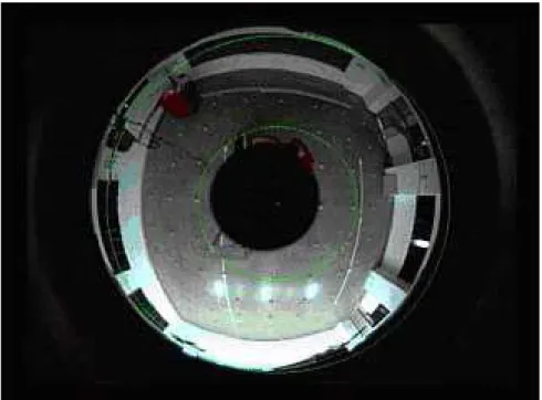
Fig. 1. It is given by the intersection of the edges estimated from vertical objects.
2 Vision System Setup and Camera Calibration
The proposed vision system for homecare surveillance is mounted on the ceiling of an indoor environment. It contains a CCD camera with a PAL (Panoramic Annular Lens) optical system [9], a frame grabber, and a PC. The video sequences are transferred to the PC at a frame rate of 7.5 fps with image resolution of 640 × 480 pix-els. The PAL optics consists of a single glass block with two reflective and two refractive planes, and has a single center of projection. Thus, the captured concentric omnidirectional image can be unwarped to create a panoramic image provided that the equivalent focal length is available.
Camera calibration of the omnidirectional vision system includes two parts– one is to derive the equivalent focal length and image center, and the other is to find the one-to-one correspondence between the ground posi-tions and the image pixels. Although the geometry of the PAL imaging system is complex, it can be modeled by the cylindrical coordinate system with a single virtual viewpoint located at the original of the coordinate system. The panoramic image corresponding to the “virtual camera” is given by the cylinder with radius of the effective focal length. The center of the annular image, i.e., the viewpoint or origin of the virtual camera, is determined by the intersection of vertical edges in the scene. In the implementation, several upright poles were hung from the ceiling, the Sobel detector was used to obtain an edge image, followed by Hough transform for robust line fitting. To increase the stability, a sequence of images was recorded for camera calibration and the mode of the distribu-tion from the images was given as the image center. Fig. 1 shows the image center obtained using three poles hung from the ceiling. It is given by the intersection of the three edges in the annular image.
To obtain the effective focal length of the PAL imaging system, upright calibration objects (poles) with known metric are placed at several fixed locations. Suppose the height of a pole is h and its location is d from the ground projection of the camera, then the effective focal length is given by
Fig. 2. Calibration pattern for the image-ground mapping. The objects are placed on the ground with known locations.
h
dvs
f
=
(1) where v is the size of the object in pixel, and s is the pixel size of the CCD in the radial direction. Due to the characteristics of the PAL sensors, the effective focal length obtained from Eq. (1) is usually not a constant for different object sizes and locations. In the experiments, the calibration pattern was placed upright such that the projection of its midpoint appeared in the central row of the panoramic image. However, it should be noted that the image scanline does not necessarily correspond to the middle concentric circle in the PAL image.The second part of omnidirectional camera calibration is to establish the relationship between the image pix-els and the 3-D ground positions. Generally speaking, 3-D to 2-D projection is an illposed problem and cannot be recovered from a single viewpoint. However, if the object possesses additional geometric constraints such as coplanarity, collinearity, it is possible to create a lookup table with the 3-D coordinate of each image pixel. Since the lookup tables are not identical for different omnidirectional camera position and orientation, they should be obtained for the individual environments prior to any surveillance tasks. Fig. 2 shows the scattered calibration objects placed on the ground. The locations of the objects are given by physical measurements. For simplicity, it is assumed that the camera is installed such that the optical axis is perpendicular to the ground. Thus, the mapping is circular symmetric and can be derived by a one-dimensional calibration pattern. Fig. 3 shows the relationship between the image coordinate and the ground position.
3 Omnidirectional Visual Tracking
In this work, motion history image, CamShift and optical flow are used for object detection and tracking. We first describe the theoretic background of the tracking algorithms, followed by the proposed methods used in omnidirectional tracking.
Fig. 3. The relationship between the image coordinate and ground position. It is assumed that the mapping is circular symmetric.
3.1 Theoretic Background
Motion history image (MHI) is a motion representation of a moving object. In an MHI , pixel intensity is a function of the temporal history of motion at that point. In this work, a simple replacement and decay operator
r
H
⎩
⎨
⎧
−
−
=
=
otherwise
)
1
)
1
,
,
(
,
0
max(
1
)
,
,
(
if
)
,
,
(
t
y
x
Hr
t
y
x
D
r
t
y
x
H
r (2)is used, and the result is an intensity image with more recently moving pixels shown in brighter. To obtain a MHI, the foreground silhouette of the moving object should be segmented from each image using background subtraction techniques. For a sequence of image with a moving object, the most recent foreground silhouette is set as the highest values in the MHI, and a layered history of the resulting motion is then generated as the MHI. The MHI’s are updated for each image frame, and the earlier motions have decreasing values subject to a threshold below which the value is set to zero. The MHI can be used to create a motion gradient image by find-ing the orientation and magnitude of the gradient given by the Sobel operator. The resultfind-ing gradient can be further used to estimate the direction of motion flow of the object.
CamShift algorithm operates on the color probability distribution image produced from histogram back pro-jection. Each image frame is converted to a color probability distribution image via a color histogram model of the color being tracked. Although the core of the CamShift algorithm is the Mean Shift algorithm [10], it is de-signed for dynamically changing distributions rather than static distributions. Thus, the CamShift algorithm adjusts the search window size during the object tracking. In our implementation, the algorithm is modified with the following steps:
(i) Choose the initial location of the search window.
(ii) Perform Mean Shift algorithm and find the zeroth moment, which is given by
∑∑
=
x yy
x
I
M
00(
,
)
(3)where
I
(
x
,
y
)
is the pixel (probability) value at position(
x
,
y
)
in the image, andx,
y
range over the search window.(iii) Set the new search window size based on the derived zeroth moment. (iv) Repeat steps (ii) and (iii) until convergence.
For general object such as human face, the result usually converges in several iterations. Optical flow represents the image changes due to the motion during a time interval, and its computation is based on two assumptions– (i)
The observed brightness of any object point is constant over time. (ii) Nearby points in the image plane move in a similar manner [11]. Let refer to the gray-level of the point (x, y) at time , then the optical flow is
to find such that
)
,
,
(
x
y
t
f
t
t y xd
d
d
,
,
)
,
,
(
)
,
,
(
x
d
y
y
t
d
f
x
y
t
f
+
x+
y+
t=
(4) If are very small, the equation is equivalent to computing the motion velocity subject to the equation t y xd
d
d
,
,
( v
u
,
)
v
f
u
f
f
t=
x+
y−
(5) where t xd
d
u
=
and t yd
d
v
=
. It is clear from the above equation that the gray-level difference at the same location of the image at timest
andt
f
t
d
t
+
is a product of spatial gray-level difference and velocity in this location according to the observer. Determination of the optical flow is then based on a Gauss-Seidel iteration method using pairs of consecutive dynamic images [12].3.2 Omnidirectional Tracking
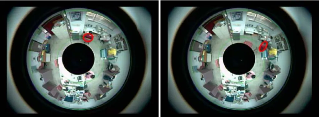
To detect the object motion in the surveillance environment, the background model is first created using pixel brightness according to normal distribution with several image frames. A motion history image, a scalar-valued image where intensity is a function of recency of motion, is generated to rapidly determine where a motion oc-curred, how it ococ-curred, and in which direction it occurred [13]. CamShift algorithm is then used for object tracking by extracting color information of the mobile target. It finds the mode of a color distribution within a video sequence based on a robust non-parametric technique for climbing density gradients [10]. CamShift algo-rithm is commonly used for face tracking, and the initial tracking region is selected according to the location and size of the face. For the omnidirectional tracking of a person, the body part which contains uniform color of cloth is used for CamShift algorithm. Fig. 4 shows the tracking result of the CamShift implementation.
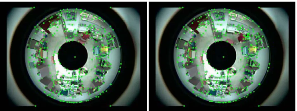
Fig. 4. The left image shown the original image. The right image is the tracking result using CamShift algorithm. The tracked target is shown by a red ellipse. The axes can be used to represent the direction of the motion.
One major drawback of the CamShift algorithm is the requirement of manual selection of the ROI (region of interest) prior to object tracking. This step is to extract the color distribution of the target. To make the motion detection and object tracking fully automatic and more robust under different illumination conditions, the optical flow approach is cooperated to detect small changes of the mobile object. Motion flow of the target given by the initial image frames (typically 5 to 10 images) is used to select the ROI for CamShift tracking algorithm. Fur-thermore, a constrained single vector derived from the average of the optical flow is used to represent the motion vector of the target. It provides a way to relocate the ROI in case that CamShift loses tracking due to illumina-tion changes in the scene. The moillumina-tion vectors estimated from optical flow also gives the trajectory of the object
motion independent of color information of the scene. Figs. 5 and 6 show the results of optical flow and the combination of CamShift and optical flow, respectively.
Since the geometric projection model of the omnidirectional vision sensor is different from the conventional pinhole camera model, the recorded video sequences have to be unwarped to generate panoramic images for better viewing purpose. Thus, camera calibration of the omnidirectional sensor involves finding the equivalent optical center and focal length of the camera, i.e., the origin and radius of the cylindrical image representation. A simple calibration method using upright object edges is implemented [14]. Image unwrapping requires a map-ping from a concentric area to a rectangular area. To reduce the undesired resampling effect, the mapmap-ping is based on the circle with the average radius of the inner and outer circles. Suppose the center of the PAL image
is , then the cylindrical panoramic image
)
,
(
x
y
I
(
x
0,
y
0)
I
(
r
,
θ
)
is generated by 2 0 2 0)
(
)
(
x
x
y
y
r
=
−
+
−
(6) 0 0 1tan
x
x
y
y
−
−
=
−θ
(7)Fig. 5. Tracking result using optical flow. The vectors represent the image gradient change above a threshold.
Fig. 6. Tracking result from the combination of both methods. CamShift is represented by a red ellipse and optical flow is represented by a blue vector.
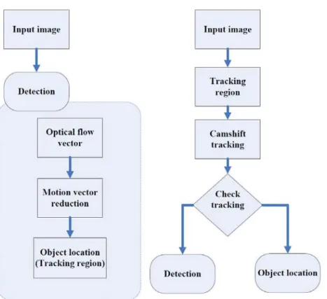
Fig. 7. The flowchart of the surveillance system.
Fig. 8. 360° unwrapped image with tracking result.
Fig. 8 shows a 360° unwarped image with object tracking result. The camera is also calibrated to obtain the one-to-one correspondences between the image pixels and the points on the ground. Since the mapping varies for different height of the camera location, it is created for the surveillance environment and used for activity moni-toring.
4 Combination of CamShift and Optical Flow
This section discusses the combination of these two fundamental algorithms to achieve the robust surveillance. First, assume there are a lot of motion vectors which calculated from optical flow. The motion vectors distrib-ute full of omnidirectional image.
i
v
)
,
,
(
x y t iOF
d
d
d
v
=
(8) where is the optical flow algorithm. represents the motion vector. In order to locate the moving per-son, a constraint is adopted to reduce the motion vectors. And we observe the motion vectors and moving perper-son, the long length vectors follow the moving person usually. The other vectors have the uncertain direction and small motion. We consider those vectors are noise, so it is easy to find the reduction constraint.(.)
⎩
⎨
⎧
≥
=
otherwise
k
v
lenght
if
v
kill
v
keep
v
i i i i)
(
)
(
)
(
(9)where k is a constant value. Length is the length of a motion vector. The location of the moving person is calculated by averaging of the remaining motion vectors. We call the above procedure is “Detection” shown in Fig. 7. The moving person could be detected by the “Detection” step. But the cost of the CPU time is expensive. To perform the real-time processing of the surveillance, the CamShift tracking algorithm is adopted to track the moving object.
)
(
v
iAs mention in section 3.2, CamShift might loses tracking due to illumination changes in the scene. To solve the problem, a method is to reuse the motion vectors which detected by optical flow algorithm. The optical flow algorithm is applied to detect the motion vectors, but the detection region is nearby the previous position of the moving person. The equations are as follows:
⎩
⎨
⎧
∈
∈
=
∑
OF
R
if
w
R
w
age
i
w
i iIm
)
(
0
(10)where is a position of the , is a region of the omnidirectional image. The equation is used to relocate (or check tracking, see Fig. 7) the ROI which CamShift could revise the tracking target. Fig. 7 is the flowchart of the proposed robust surveillance system
.
i
R
w w
5 Human Activity Recognition and Fall Detection
In the home environment, there are typically several places where people spend most of their time without sig-nificant motion changes, such as chairs, beds, or the regions close to the television or computers. These places can be marked as “inactivity zones” and usually have little changes in the visual surveillance. On the other hand, there are some places involve frequent changes in the scene such as the hallway, entrance to the room, and free space in the environment. These regions are referred to as “activity zones” since most of the detectable motion changes happen in those areas. There is also a third case called “non-activity zones”, which indicate that any normal human activities should not occur in the regions. Based on the above classification, the surveillance environment is partitioned into three regions. An abnormal behavior warning system is established according to the activities happened in the different zones.
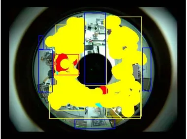
Fig. 9 shows the trajectory of the human motion after 3121 frames of omnidirectional tracking in the indoor environment. The isolated points are due to the low frame rate of image acquisition (7.5 fps). The density of the
Fig. 9. The trajectory of the human motion after 3121 frames of omnidirectional tracking, the data points are shown in red. It means the non-red points are not safe for active of the environment.
Fig. 10. Based on the trajectory observed in Fig. 9, the indoor environment is partitioned into three regions. data points in the image is used to classify the three different regions. As illustrated in Fig. 10, the yellow color region is the activity zone, which contains low density data points. The regions consist of little changes during a long period is shown in the red bounding box, which is classified as the inactivity zone. The rest of the surveil-lance area is assigned by blue bounding box, which is used to provide the information about non-activity zone.
It is clear that the size of an object appeared in the image depends on the location of the object, even for the omnidirectional imaging sensors. Based on this fact and the above calibration information, the projected height of an object (or a person) with known physical dimension can be computed for different ground position in a concentric manner. Thus, fall detection of the target can be given by identifying its standing position (the bottom) and its top. By comparing the object length appeared in the image and the computed length according to the object’s physical height, some activities of the object such as falling, sitting, etc. can be detected. To make the fall detection algorithm more robust and to avoid false alarm, the motion vectors obtained from optical flow are used to detect the sudden changes of the object’s height and motion direction. Fig. 11 shows fall detection and length change of the object at different locations.
Fig. 11. Fall detection with predicted length. Note that the object size in the image is not fixed for different locations even if the object physical height is not changed.
6 Conclusion
Visual surveillance is one of the important topics in the nursing and homecare systems. In this work, we have proposed a video surveillance system using an omnidirectional CCD camera and combined different algorithms for robust human motion tracking as shown in Fig. 12. Automatic object detection, people tracking, fall detec-tion, and surveillance region classification for abnormal behavior warning have been implemented. Experimen-tal results with several hours of video surveillance are presented. In the future research, a PTZ camera will be combined with the omnidirectional tracking system to obtain a closer look of the target for recognition purposes. Human activity will also be analyzed and discussed in more detail.
Acknowledgement
The support of this work in part by the National Science Council of Taiwan, R.O.C. under Grant NSC-94-2213-E-194-041 is gratefully acknowledged.
(a) Experimental results one detected motion by the optical flow algorithm. The green points follow the moving person.
(b) Experimental results two detected motion vectors by the optical flow algorithm. The red arrows show the moving direc-tion of the person.
(c) Experimental results three reduced the noise motion vectors.
(d) Experimental results four tracked the moving person by the CamShift.
Frame 28. Frame 30. Frame 36.
(e) Experimental results five contain the figures relocated the moving person while the CamShift loses track.
Fig. 12. Experimental results of the robust visual surveillance system.(Continued)
References
[1] G. L. Foresti, P. Mahonen, and C. S. Regazzoni, Multimedia Video-Based Surveillance Systems: Requirements, Issues
and Solutions, Kluwer Academic Publishers, 2000.
[2] H. Kruegle, CCTV Surveillance: Video Practices and Technology, Butterworth-Heinemann, 1996.
[3] C. S. Regazzoni, G. Fabri, and G. Vernazza, Advanced Video-Based Surveillance Systems, Kluwer Academic Publishers, 1998.
[4] G. Medioni and S. B. Kang, Emerging Topics in Computer Vision, Prentice Hall PTR, 2004.
[5] E. Menegatti, A. Scarpa, D. Massarin, E. Ros, and E. Pagello, "Omnidirectional Distributed Vision System for a Team of Heterogeneous Robots," Proceedings of IEEE Workshop Omnidirectional Vision, pp. 87-94, 2003.
[6] Stratmann, I, "Omnidirectional imaging and optical flow," Proceedings of Omnidirectional Vision, pp. 104-111, 2002. [7] Qiang Liu, Canhui Cai, Ngan, K.N., and Hongliang Li, "Camshift based real-time multiple faces match tracking,"
Intelli-gent Signal Processing and Communication Systems, pp. 726-729, 2007.
[8] MacDorman, K.F. Nobuta, H. Koizumi, S. and Ishiguro, H., "Memory-Based Attention Control for Activity Recognition at a Subway Station," IEEE Multimedia, Vol. 14, Issue 2, pp.38-49, April-June 2007.
[9] P. Greguss, Panoramic imaging block for three-dimensional space, U.S. Patent 4,566,763, 28 Jan., 1986.
[10] Y. Cheng, "Mean Shift, Model Seeking, and Clustering," IEEE Transactions on Pattern Analysis and Machine
[11] E. Trucco and A. Verri, Introductory Techniques for 3D Computer Vision, Prentice Hall, 1998. [12] B. K. P. Horn, Robot Vision, McGraw-Hill Book Company, 1986.
[13] J. Davis and A. Bobick, "The Representation and Recognition of Action Using Temporal Templates," MIT Media Lab
Technical Report 402, 1997.
[14] Z. Zhu, K. D. Rajasekar, E. Riseman, and A. Hanson, "Panoramic virtual stereovision of cooperative mobile robots for localizing 3-D moving objects," Proceedings of IEEE Workshop Omnidirectional Vision, pp. 29-36, 2000.
[15] G. Bradski and J. Davis, "Motion Segmentation and Pose Recognition with Motion History Gradients," IEEE WACV ’00, 2000.
[16] C. Geyer, K. Daniilidis, "Catadioptric Camera Calibration," Proceedings of the 7th International Conference on
Com-puter Vision, ICCV 1999.
[17] S. J. McKenna, F. Marquis-Faulkes, P. Gregor, A. F. Newell, "Scenario-based Drama as a Tool for Investigating User Requirements with Application to Home Monitoring for Elderly People," Proceedings of the 10th International
Confer-ence on Human-Computer Interaction, Crete, Greece, June 2003.
[18] Shree K. Nayar, "Omnidirectional Vision," Proceedings of the Eight International Symposium on Robotics Research
(ISRR), Shonan, Japan, October 1997.
[19] H. Nait-Charif and S. J. McKenna, Activity Summarisation and Fall Detection in a Supportive Home Environment,
Proceedings of International Conference on Pattern Recognition (ICPR), Cambridge, August 2004.