A Novel Simplified Space-Vector Modulated Control Scheme
for Three-phase Switc
Chern-Lin Chen, Che-Ming Lee, Rong-Jie Tu,
and
Guo-Kiang Homg
Power Electronics Laboratory Department of Electrical Engineering
National Taiwan University Taipei, Taiwan Abstract
-
A novel simplified control scheme for three-phase switch-mode rectifier is proposed in this paper. The proposed control scheme is based upon a load-conductance rectifier controller, in which reference current signals are obtained. The goal to follow the reference current is converted to follow a reference voltage. A simplified control scheme utilizing space-vector modulation is developed to calculate the duty ratio required to synthesize the reference voltage. The proposed scheme has the advantage of space-vector modulation with fast dynamic response, and being simple enough to be implemented in a low-cost microprocessor.
I. INTRODUCTION
Switch-mode rectifiers (SMRs) have gained increasing interests of research recently for improving power factor deterioration. A conventional three-phase boost-type SMR is consisted of six switches with anti- paralleled diodes as shown in Fig. 1. This system is ideally applicable to DC-linked AC motor drives since it draws sinusoidal input currents, and controls the DC bus voltage. Moreover, its capability of bi-directional power flow allows regenerative operation, which is especially advantageous for high-power applications. The main drawback is that a more complicated control scheme and six corresponding driving circuits are required to control the six switches individually.
A simple hysteresis current control scheme for three-phase SMR is discussed in several papers [ 1,2]. The input phase current is individually controlled to track the corresponding template current waveform. It is capable of delivering nearly sinusoidal current waveforms with unity power factor. However, the switching pattern is random. This increases the switching losses and deteriorates the system performance.
Lately, the space-vector modulation method for
three-phase SMR is proposed [3]. The input phase voltages are divided into six 60-degree intervals where no sign change occurs. Excellent power factor is obtained by controlling only two currents in each interval. The space-vector approach can provide fast dynamic control and stability, but is quite complicated to implement and require significant computational resources. High speed microprocessors or digital signal processors are required.
This paper presents a simplified space-vector modulated control scheme for three-phase SMR. In this control scheme, the reference current signals are obtained by load-conductance controller [4,5]. The goal to follow the reference current is converted to follow a reference voltage. A simplified control scheme utilizing space-vector modulation is developed to calculate the duty ratio required to synthesize the reference voltage. Experimental verification is carried using a low-cost microprocessor 80 196MC. Experimental results with sinusoidal input current and nearly unity power factor are observed.
a b
0
C ad
Fig. 1. Three-phase boost-type switch-mode rectifier
11. PROPOSED SCHEME
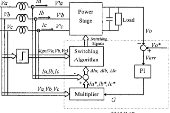
Fig. 2 illustrates the block diagram of the The power stage is six proposed control scheme.
switches with anti-paralleled diodes as shown in Fig. 1.
80196MC Fig. 2. Block diagram of the proposed control scheme
1358
The controller part (inside the dashed square) is accomplished using a low-cost microprocessor 80196MC. The details of the proposed control scheme are explained as follows.
A)Load Conductance Calculation
The reference current signals are obtained based on the load conductance controller. The error between the reference and measured link capacitor voltage is processed through a PI controller. The output of the PI controller is defined as the rectifier load conductance G
[4,5]. The reference current signals are generated by the product of the load conductance and the input phase voltages. Therefore, if the input current is controlled to follow the current command, it follows the input voltage in its waveform and follow the load conductance in its magnitude.
B)Model Development
The input phase voltages can be divided into six 60-degree intervals where no sign change occurs as shown in Fig. 3. Take interval I for example, Vu and
Vb are positive, and Vc is negative. Since input currents are to be controlled to be in phase with input voltage, l a and Ib are positive, and
IC
is negative. In such condition, there will be no current flowing throughSa, Sb, S'c, D'a, D'b, and Dc. According to the states
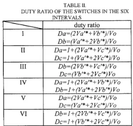
of S'a, S'b and Sc, there are eight operation modes, only four of which will be used in the proposed control scheme. Table I. illustrates the voltage vectors obtained in the four operation modes in interval I. The voltage vectors will be explained in the next section. Note that Sc is always set OFF in interval I, thus switching loss can be greatly reduced.
'
I I1 111 IV v V IFig. 3 Input phase voltages are divided into six 60-degree intervals
TABLE I
C)Space- Vector Modulation
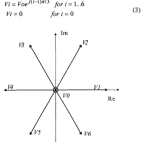
With the concept of the space vector, it is convenient to represent three-phase quantities (voltages and currents) as a space vlector:
where
a
= e J 2 X / 3 . Consequently, voltages before the rectifier bridge V'a, V'b, and V'c can be represented as a voltage vector V'.According to the states of the six switches, there are seven voltage vectors as shown in Fig.4, where
t
I mi
Fig. 4. Voltage vector representations of Vu, V'b, and V'C
Also, the input phase voltages and currents can be represented as space vectors:
(4)
2 V = Va
+
Vb x a+
Vi; x a( 5 )
I = l a
+
Ib xa
+
Ic xa L
From Fig. 2 the following equation can be obtained: ( 6 )
( V - V ' * ) = L A l f A T
where L=La=Lb=Lc and AT is the switching period. Eq. (6) states that the current error vector is a fimction of the voltage vector V and V' (i.e. the operation modes). The proper voltage vector command V'* can be decided according t'o the desired current error vectors AI and the input voltage vector V. Then the appropriate conducting states of the switches can be decided. For example, if V'* is located as shown in
Fig. 5 , it can be synthesized using VO V1 and V 2 , which satisfies the following equations:
I ( 7 ) (8) ATV
'*
= TOVO+
T l V l+
T2V2 TO+ T1+ T 2 = AT duty ratio Da= (2 Vu'*+
Vb '*)/Vo Db =1Va'*+2 Vb '* W OEq. ( 7 ) and (8) can be solved to obtain the following:
I1 I11 IV V VI ~ AT v o TO= A T - T 1 - T 2 Da=1+(2Va'*+Vcr*)/Vo Dc = 1 +(Vu
'*
+2 Vc '*)/Vo Db=(2Vb'*+ Vc'*)/Vo Dc = (Vb'
*
+2 Vc'*)
Vo Da = I+
(2 Va'
*
+ Vb'
*)/Vo Db = 1 +(Vu '*+2 Vb'*)
Vo Da=(2Va'*+ Vc'*)/Vo Dc =( Va'*+2 Vc '*)/Vo Db = 1+
(2 Vb'*+
Vc '*)/Vo Dc = 1+
(Vb'
*
+2 Vc '*)NoHowever, this algorithm requires complicated computations with complex numbers. A high speed microprocessor or digital signal processor must be used to encounter these computations.
A
V.5
J
I
L
V6Fig. 5 . Synthesis of voltage vectot
D)Simpliped Control Scheme
To make the space vector modulation scheme applicable in a low-cost microprocessor such as
80 196MC, the calculation process must be simplified.
According to Table I, three voltage vector can be obtained in the four operation modes of interval I by just controlling two legs of the bridge. If VI* is located as in Fig. 5, by substituting the voltage values in Table I. into Eq. (7), the following equations can be obtained:
2 1
3 3
-1 1
ATVa'* = TO x O + T l x - V o + T 2 x-Vo (12) ATVb'* = TO x 0
+
T1 x -VO+ 3 T 2 x -VO 3 (13)Solving Eq. (12) and ( 1 3): Tl Vu'*-Vb'" AT v o
_ -
- (14) 1360 T 2 Va'*+2Vb'* AT v o - --
Sa is on for VI and V2, and Sb is on for V2. The duty ratio Da and Db of Sa and Sb thus can be obtained:
T1 T 2 2Va'*+Vb'* AT AT T 2 Va'*+2Vb'* AT v o (16) (17) Da =
-
+-
= v o Db=-=Note that in interval I , V'* will be located only in the shaded area in Fig. 5. If V'* is located where VO, V2 and V 3 must be used to synthesize it, the duty ratio
obtained will be exactly the same as eq. (16) and (17). Similarly, operations during the other intervals can be obtained as Table 11. By using the simplified control scheme, the space vector modulation can be implemented in a low-cost microprocessor such as
80196MC.
111. Experimental Results
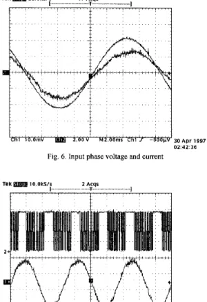
A three-phase boost-type SMR with the proposed simplified control scheme is implemented and tested in the laboratory. The controller part is accomplished in a low-cost microprocessor 80 196MC. A sinusoidal input current in phase with the corresponding input phase voltage is obtained as shown in Fig. 6 . Fig.7 shows one of the gate driving signals and the input phase current. It is seen that the AC switch is set normally open in one
third of the operation cycle. Therefore the switching losses are greatly reduced.
.MY : I
. m ms - )1 3 0 A p r 1997
02 4 2 36 [hl io , v , ~2 , 0 0 v ; , , , M Z , O b ' , 'Chi , 600
J
Fig 6 Input phase voltage and current
TeK I O OkS/s 2 ACqS
7
0 2 38.28
Fig 7 One of the gate driving signals and the input current
IV. CONCLUSIONS
This paper presents a novel simplified space- vector modulated control scheme for three-phase boost- type SMR. The main drawback of the circuit topology is the cost of the extra switches and driving circuits. Also, complicated control scheme is required. However, remarkable advantages are obtained using the proposed control scheme:
Employing the conventional three-phase boost- type SMR allows bi-directional power flow, which is very important in high power motor drive applications.
The six-switch module with anti-paralleled diodes is just the same as that used in the inverter, which is readily available.
Only two legs of the bridge are controlled in each operation interval. The overall switching power losses are greatly reduced.
The proposed control scheme utilizes the space- vector modulation technique, which has the advantage of fast dynamic response and stability.
The proposed control scheme simplifies the calculation process of the space-vector modulation, which makes it possible to be implemented in a low-cost microprocessor such as
80 196MC.
V. REFERENCES
B.T. Ooi, J.C. Salmon, J.W. Dixon, and A.B. Kulkami, "A 3- phase controlled current converter with leading power factor," pp. 78-84, IEEE, Trans. Indus. Appl., Vol. IA-23, No. 1, 1987.
J.W. Dixon, A.B. Kulkarni, M. Nishimoto, and B.T. Ooi, "Characteristics of a controlled current PWM rectifier link," pp. 685-691, IEEE, IAS, Conference Proceeding, 1986. R. Wu, S.B. Dewan, G.R. Slemon, "A PWM AC-to-DC converter with fixed switching frequency," pp. 880-885, IEEE,
Trans. Indus. Appl., Vol. IA-26, No. 2, 1990.
J. H. R. Enslin and J. D. Van Wyk, "A new control philosophy
for power electronic converters as fictitious power
compensators," IEEE Trrms. Power Electron., vol. 5 , pp. 88-
97, Jan. 1990.
S. Bhowmik, A. van Zyl, R. Spee, and J. H. R. Enslin,
"Sensorless current contrlol for active rectifiers," IEEE Trans.
Indus. Appli., vol. 33, no. 3, pp.765-772, May/June 1997.