本研究報告提出一頻域光波導模態的高階精確計算方法和其應用。我們以擬譜法為基礎將
麥克士威方程式進行離散,邊界條件的配置是以補償法嵌入格式中,所得的方程為線性系
統方程組
。我們對格式進行了詳細的穩定性分析,接著進行程式編寫和測試。計算結果與
理論分析是一致的。最後,我們以演算法對各類光波導進行傳播特性分析,並討論計算的
物理現象。
In this report, we propose a high-order accurate scheme for computing optical waveguide
modes. We employ the Legendre pseudospectral method to discretize the Maxwell’s
equa-tions. Boundary conditions are imposed to the scheme through the penalty methodology.
This approach leads to a system of linear equations. We pay special attention to analysis
the stability of the schemes, and we obtain suitable penalty parameters for stable
computa-tions. The numerical method is validated through direct computations, and the results are
consistent with the theoretical analysis. In addition, we conduct optical wave analysis for
various kinds of waveguides to study wave propagations in these devises.
關鍵字:擬譜法,邊界補償法,頻域麥克士威方程式,光波導
Keywords: pseudospectral methods, penalty boundary conditions, frequency-domain Maxwell’s
equations, optical waveguides
Frequency-domain (FD) and Time-domain (TD) computational electromagnetic (EM)
meth-ods are playing important roles in optic wave analysis. To investigate the transition of EM
waves, TD methods (see [10, 11, 14, 15] for example) are suitable. On the other hand, FD
al-gorithms [4, 7, 8, 12, 13] are commonly used for studying the time-harmonic electromagnetic
wave properties, since the methods solve EM wave problems based on a single frequency. In
this report we describe a novel method for computing accurate propagation characteristics
of optical waveguide of complex geometries.
The traditional methods for analyzing optical waves in guiding devises are based on
solving the Helmholtz equations which involves second derivatives in space. The numerical
formulations results into linear systems of equations having large condition numbers, due
to the numerical second differential operators. Hence, the numerical solutions require many
iterations to converge within the desired accuracy. To overcome this issue we propose a
formulation based on the Maxwell’s equations which involves first derivatives in space only.
Thus, the condition numbers of the Maxwell-based formulation are smaller than those of the
Helmholtz-based formulation. This leads to less iteration steps toward to the convergence
of solutions. Moreover, another potential advantage of using the Maxwell equations based
formulation is that one can directly borrow important numerical theories developed from the
TD Maxwell equations based computational framework [10, 11], for instance, the penalty
methodology for imposing boundary conditions [5, 6, 9] and perfectly matched layer type
absorbing boundary conditions [1, 2, 3] which have been used in real applications.
In addition, inspired by the constructed pseudopsectral FD method for optic waveguide
analysis, we construct an error minimized pseudospectral penalty direct Poission solver. It is
found the that imposition of boundary conditions has great effects on the solution accuracy
and the penalty parameters can be obtained analytically to yield numerical solutions with
error being minimized. Numerical experiments are conducted and the results are consistent
with the theoretical analysis. The method is very easy to implement and it can help improve
the accuracy of pseudospectral Poission solver used in the scientific community.
papers included in this report.
1. C. Y. Wang, S. Y. Chung, C. H. Teng, J. K. Wang, C. P. Chen, H. C. Chang, A
high-accuracy multidomain Legendre pseudospectral frequency-domain method with
penalty scheme for solving scattering and coupling problems of nano-cylinders, IEEE/OSA
J. Lightw. Technol., 31, pp. 768-778, (2013).
(SCI), IF=2.782, Ranking 5/79 ≈ 6.3% in Telecommunication.
. . . .
2. S. F. Chiang, B. Y. Lin, H. C. Chang, C. H. Teng, C. Y. Wang, S. Y. Chung, A
multidomain pseudospectral mode solver for optical waveguide analysis, J. Lightw.
Technol., 30, pp. 2077-2087, (2012).
(SCI), IF=2.782, Ranking 5/79 ≈ 6.3% in Telecommunication.
. . . .
3. T. L. Horng, C. H. Teng, An error minimized pseudospectral penalty direct Poisson
solver, J. Comput. Phys., 231, pp. 2498-2509, (2012)
(SCI) IF: 2.310, Ranking 5/55 ≈ 9.1% in Physics, Mathematics.
. . . .
References
[1] Abarbenel S., Gottlieb D. (1998). On the construction and analysis of absorbing layer
in CEM. Appl. Numer. Math., 27, 331-340.
[2] Abarbenel S., Gottlieb D., Hesthaven J. (1999). Well-posed Perfectly Matched Layers
for Advective Acoustics. J. Comput. Phys., 154, 266-283.
[3] Berenger J. P. (1994). A perfectly matched layer for the absorption of electromagnetic
wave. J. Comput. Phys., 114, 185-200.
[4] Chiang Y. C., Chiou Y. P., Chang H. C. (2002). Improved full-vectorial finite-difference
mode solver for optical waveguides with step-index profiles. J. Lightw. Technol., vol. 20,
no. 8, pp. 1609-1618.
[5] Funaro D., Gottlieb D. (1988). A new method of imposing boundary conditions in
pseudospectral approximations of hyperbolic equations. Math. Comp. 51, 599-613.
[6] Funaro D., Gottlieb D. (1991). Convergence results for pseudospectral approximations
of hyperbolic systems by a penalty-type boundary treatment. Math. Comp. 57, 585-596.
3
pp. 1210-1218.
[8] Hadley G. H. (2002). High-accuracy finite-difference equations for dielectric waveguide
analysis II: Dielectric corners. J. Lightw. Technol., vol. 20, no. 7, pp. 1219-1232.
[9] Hesthaven J. S. (2000). Spectral penalty methods. Appl. Numer. Math., 33, 23-41.
[10] Hesthaven J. S., Gottlieb D. (1999). Spectral collocation time-domain modeling of
diffractive optical elements. J. Comput. Phys., 155, 287-306.
[11] Hesthaven J. S., Warburton T. (2002). Nodal high-order methods on unstructured grids.
I. Time-domain solution of Maxwell’s equations. J. Comput. Phys., 181, 186-221.
[12] Jiang P. J., Wu C. L., Teng C. H., Yang C. S., Chang H. C. (2008). Full-Vectorial
Optical Waveguide Mode Solvers Using Multidomain Pseudospectral Frequency-Domain
(PSFD) Formulations. IEEE Journal of Quantum Electronics, 44, 56-66.
[13] M.Koshiba M., Tsuji Y. (2000). Curvilinear hybrid edge/nodal elements with triangular
shape for guided-wave problems. J. Lightw. Technol., vol. 18, no. 5, pp. 737-743.
[14] Taflove A., Hagness S. C. (2000). Computational Electrodynamics:
The
Finite-Difference Time-Domain Method (2nd ed). Artech House, Boston, London.
[15] Yee, K. S. (1966). Numerical solutionn of initial boundary value problems involving
Maxwell’s equations in isotropic media. IEEE Trans. Antennas Propagat., 14, 302-307.
A High-Accuracy Multidomain Legendre
Pseudospectral Frequency-Domain Method With
Penalty Scheme for Solving Scattering and
Coupling Problems of Nano-Cylinders
Chih-Yu Wang, Shih-Yung Chung, Chun-Hao Teng, Juen-Kai Wang, Chung-Ping Chen, Member, IEEE, and
Hung-chun Chang, Senior Member, IEEE, Fellow, OSA
Abstract—A new multidomain pseudospectral
frequency-do-main (PSFD) method based on the Legendre polynomials with penalty scheme is developed for numerically modeling electromag-netic wave scattering problems. The primary aim of the proposed method is to more accurately analyzing scattering and coupling problems in plasmonics, in which optical waves interact with nanometer-sized metallic structures. Using light scattering by a silver circular cylinder as a first example, the formulated method is demonstrated to achieve numerical accuracy in near-field calculations on the order of with respect to a unity field strength of the incident wave with excellent exponentially con-vergent behavior in numerical accuracy. Then, scattering by a dielectric square cylinder and that by several coupled metallic structures involving circular cylinders, square cylinders, or di-electric coated cylinders are examined to provide high-accuracy coupled near-field results.
Index Terms—Electromagnetic near fields, electromagnetic
wave scattering, plasmonics, pseudospectral frequency-domain (PSFD) method.
I. INTRODUCTION
P
LASMONICS is a relatively new field concerning the col-lective electromagnetic resonances of free electrons in-side nanometer-scaled metallic structures [1], which has beenManuscript received February 04, 2012; revised November 11, 2012, November 23, 2012; accepted November 26, 2012. Date of publication December 12, 2012; date of current version January 23, 2013. This work was supported in part by the National Science Council of the Republic of China under Grant NSC99-2628-M-002-008, Grant NSC99-2221-E-002-107-MY2, Grant NSC99-2115-M-009-012-MY3, and Grant NSC 101-2811-M-009-040, in part by the Excellent Research Projects of National Taiwan University under Grant 10R80919-1, and in part by the Ministry of Education of the Republic of China under “The Aim of Top University Plan” Grant.
C.-Y. Wang, S.-Y. Chung, and C.-P. Chen are with the Graduate Institute of Electronics Engineering and the Department of Electrical Engineering, National Taiwan University, Taipei 10617, Taiwan.
C.-H. Teng is with the Department of Applied Mathematics and Center of Mathematical Modeling and Scientific Computing, National Chiao Tung Uni-versity, Hsinchu 30010, Taiwan.
J.-K. Wang is with the Institute of Atomic and Molecular Sciences, Academia Sinica, and the Center for Condensed Matter Sciences, National Taiwan Univer-sity, Taipei 10617, Taiwan.
H. Chang is with the Department of Electrical Engineering, the Graduate Institute of Photonics and Optoelectronics, and the Graduate Institute of Com-munication Engineering, National Taiwan University, Taipei 10617, Taiwan (e-mail: [email protected]).
Digital Object Identifier 10.1109/JLT.2012.2233714
widely studied and applied in many areas, like surface enhanced Raman scattering (SERS) [2], nanoantennas [3], waveguides [4], etc. Strong electromagnetic fields can be locally enhanced and radiated by this collective oscillation of electric charges. The field coupling between metallic nanoparticles under dif-ferent incident polarizations thus plays an important role in such plasmonics research. Accurate electromagnetic near-field cal-culation is essential and significant for understanding the un-derlying optical behaviors [5]. However, due to the nanometer-sized dimension and spacing of metallic particles as well as strongly enhanced near fields, there exist challenges to achieve relevant numerical simulations with good accuracy. The Mie theory [6] and the multiple scattering methods [7], [8] for ana-lytically calculating light wave scattering by spheres or circular cylinders have been proposed. But for more general geometries of the plasmonic objects, numerical methods, like the finite-dif-ference time-domain (FDTD) method [9], [10] and the finite ele-ment method (FEM) [11], [12], could provide more flexibilities. Plasmon resonance and field enhancement in complicated struc-tures have also been analyzed using the surface integral method [13] and the volume integral method [14] and discussed by the surface-charge hybridization picture [15].
To more accurately model the interaction of electromag-netic waves with metallic structures, we present here a new Legendre pseudospectral frequency-domain (PSFD) method to solve Maxwell’s equations for relevant two-dimensional (2-D) scattering problems. Although not so popularly used, the pseu-dospectral methods have been demonstrated their high-order accuracy and fast convergence behavior in applications to computational electromagnetics in time domain [16]–[19]. The idea of the pseudospectral method in frequency domain was initially proposed by Liu [20] based on Chebyshev polynomials and the second-order Helmholtz equation to solve a scattering problem. Later, based on Helmholtz equations, pseudospectral eigenmode solvers have been established for analyzing 2-D photonic crystals [21] and obtaining full-vector optical wave-guide modes [22]. In this paper, we formulate our new PSFD method, instead, from the first-order differential equations using the similar scheme of a related Legendre pseudospectral time-domain (PSTD) method recently established [23] and utilizing the Legendre polynomials as the interpolation basis. Besides, the penalty scheme as developed in [23] is used to better handle boundary conditions for well-posedness consid-eration, and the perfectly matched layers (PMLs) [24]–[26] 0733-8724/$31.00 © 2012 IEEE
are incorporated into the PSFD formulation to absorb out-ward propagating waves and effectively reduce reflection of out-going waves. The multidomain approach is employed, as in [23], with which the computational domain with the PMLs is divided into suitable number of subdomains, with the material interfaces fitting the sides of some subdomains, so that the field continuity conditions can be accurately fulfilled. The equations approximating the physical processes of the corresponding sub-domains are finally packed into a linear matrix equation which can be easily solved by iterative algorithms. Using the PSFD method, we will show that numerical accuracy on the order of can be achieved in the scattered-field calculation of a circular metallic cylinder, as compared with known analytical results provided in [27], [28]. More importantly, this PSFD method provides exponentially convergent rate in numerical accuracy with respect to grid resolution, which implies its effi-ciency in that few grid points added can exponentially increase computation accuracy. We believe this method can provide high-accuracy results in the analysis of electromagnetic field characteristics of plasmonic problems including the important ones of coupled cylinder structures.
The finite-difference time-domain (FDTD) method [9] has been a popular numerical analysis and simulation method in computational electromagnetics, including plasmonics. For curved material interfaces, the simple stair-casing approxima-tion of such interfaces as often utilized in the FDTD calculaapproxima-tion of the electromagnetic field may result in numerical-accuracy reduction in field values along the curved interface [29]. How-ever, obtaining high-accuracy near fields for such situations can be important for understanding the plasmonic phenomenon and proposing relevant applications. More efforts must be paid for overcoming such stair-casing problem in the FDTD method, e.g., using the conformal scheme [30], the triangular mesh [31], the effective permittivity [32], etc. The PSFD method, however, can avoid such stair-casing problem since its subdomain partitioning with curvilinear geometries can match exactly to the shape of the structure interface [33], thus can provide accurate computation.
Furthermore, in numerically modeling the plasmonic struc-tures, material dispersive properties of metals need to be carefully considered. In time-domain computation methods, the auxiliary differential equation (ADE) technique [9] can be employed to take into account the Drude-Lorentz material model for a metal in the simulation. But the parameters in the material dispersion model need to be carefully assigned through curve fitting the measured dielectric function of the metal [34], [35]. As a frequency-domain method, however, the PSFD method can directly adopt the measured or given complex dielectric constant of the metal at the considered fre-quency without needing the ADE approach and the associated curve-fitting procedure for treating material dispersion in the electromagnetic calculations.
The remainder of this paper is outlined as follows. Maxwell’s equations with the penalty scheme for the 2-D scattering problem are described in Section II. The Legendre pseudospec-tral method is introduced in Section III. Scattering calculation results for a silver circular cylinder, a dielectric square cylinder, and several coupled metallic structures involving circular cylinders, square cylinders, or dielectric coated cylinders are presented and discussed in Section IV. Some remarks on the
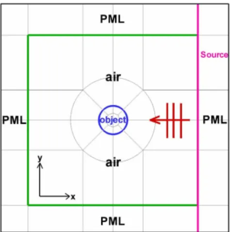
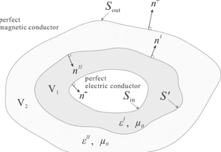
Fig. 1. Computational domain with pseudospectral subdomain division for the scenario in which a plane wave is scattered by a 2-D object.
proposed formulation and scheme are given in Section V. The conclusion is drawn in Section VI.
II. MAXWELL’SEQUATIONSWITH THEPENALTYSCHEME For time-harmonic electromagnetic fields, and , in a linear isotropic medium region with permittivity and per-meability , Maxwell’s curl equations can be written in the complex form as
(1a) (1b) where and represent the source electric and magnetic current densities, respectively, and is the angular frequency. Here, we consider the 2-D problem with no field variation along the direction. Fig. 1 shows one example scenario in which a plane wave is scattered by a 2-D circular cylinder. We particularly study the transverse-magnetic (TM) waves with , and field components because of plasmonics applications. Therefore, Maxwell’s curl equations become three first-order equations as
(2a)
(2b)
(2c)
In the multidomain PSFD method, the computational do-main is partitioned into suitable non-overlapping subdodo-mains of curvilinear quadrilateral shape. Using the scattering by a cir-cular cylinder as depicted in Fig. 1 as an example, if boundary conditions are rigorously considered at the interface between adjacent subdomains I and II with the unit normal vector perpendicular to the interface expressed as , the continuity of tangential fields across the interface for source-free dielectrics requires that
(3a) (3b)
for the TM waves, where the superscripts, and , denote the subdomains and denotes the tangential electric field, i.e.,
.
In our formulation, an incident TM plane wave is generated by assigning a uniform -directed source surface current density with unit A/m on the PML/air interface, as shown in Fig. 1,
using the required boundary condition, ,
where I and II refer to the corresponding PML subdomain and air subdomain, respectively, and is taken to be zero in (2c). This -directed would generate both -polarized rightward (to the PML) and leftward propagating plane waves [36], with the rightward wave absorbed by the PML. Note that the relation between and , the latter being the volume current density with unit A/m , is if flows in the direction, and we would have , where is the quadrature weight on the interface which will be defined in the next section.
In [23], the Legendre PSTD formulation with the penalty scheme based on well-posed boundary impositions of physical boundary conditions in terms of characteristic variables has been discussed in detail. The same penalty scheme is employed here to impose weakly characteristic boundary conditions. Briefly speaking, (2) can be first written as
(4)
where , and the
ma-trices and are simply constructed with 0, 1, and cor-responding to the presence of fields in (2). Next, the penalty term will be added. The ma-trices, and , are constructed respectively from the eigen-values and eigenvectors of the matrix , which is defined
as , and the characteristic state vectors
are defined as as in [23]. Then, after
matrix multiplications of , and in the
penalty term , Maxwell’s equations in (2) with penalty added become
(5a)
(5b)
(5c)
where is unity when the grid point is on the boundary edge, and is zero otherwise [23]. The variable is a free parameter defined by Theorem 3.1 in [23] with value for supporting (5) to be a convergent system during iteration processes. In the PML subdomains, (5) are rewritten, following the derivations in [23] and [26], as
(6a)
(6b)
(6c)
where and are absorbing profiles along the and axes, respectively, and denotes the derivative of with respect
to . Taking as an example, we choose
, where is the distance of the point, , from the initial point, is the total length of PML, and the parameters and are free variables for tuning the PML performance. After employing the Legendre pseudospec-tral scheme and packing all subdomains, (5) and (6) would lead to a linear matrix equation, , with the unknown vector consisting of and fields, the vector corresponding to the known sources, and the matrix consisting of spatial dif-ferential operators and penalty terms. The unknown electric and magnetic fields can be solved from using efficient iterative algorithms such as the bi-conjugate gradient (BiCG) method.
III. LEGENDREPSEUDOSPECTRALMETHOD
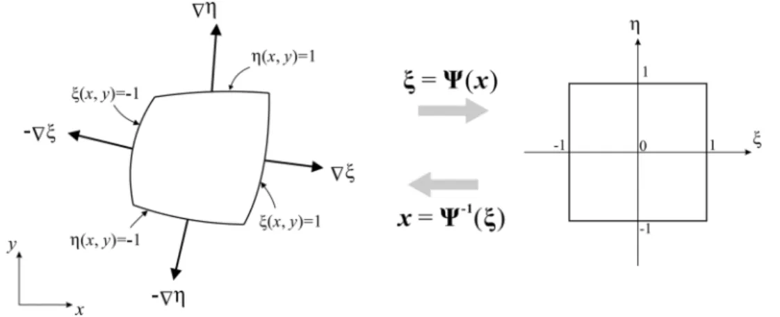
Now, we discuss the Legendre pseudospectral method for numerically treating the spatial derivatives in the above gov-erning equations. Under the multidomain scheme, each curvi-linear quadrilateral subdomain region in Cartesian coordinates
can be mapped onto a square region in
curvilinear coordinates by using the transfinite blending function described in [29] to construct and
. Applying the chain rule, derivatives of a 2-D function will then become
(7a)
(7b)
Some properties of Legendre polynomials, which we use as the basis for the interpolation of a function, will be given below.
In the Legendre pseudospectral method, spatial arrangement of grid points is defined by the Legendre–Gauss–Lobatto (LGL) quadrature points arranged in the interval , which are the roots of the polynomial [23] with the prime denoting derivative and being the Legendre polynomial of degree defined by
(8)
Associated with these LGL quadrature points are a set of
polynomial of degree at most , we have the quadrature rule [23]
(9)
where the quadrature weights are defined by
otherwise. (10)
Based on these LGL collocation points, one can use the de-gree- Lagrange interpolation polynomials as the bases to approximate an arbitrary function such that
(11)
where
(12)
Then, the derivative of the function at the LGL quadrature point can also be approximated as
(13)
The differential coefficient is defined in [23] by
otherwise
(14)
if ; and
(15)
if . The so-called differential matrix operator with elements can thus be substituted into the spatial derivative in (13) as
..
. ... ... ... (16)
This is the key feature of the Legendre PSFD method, i.e., for the 1-D example, the derivative of at an LGL point in the region can be approximated in terms of values at the LGL points in the same region. Spatial derivatives of fields in (5)–(7) can be simply replaced by these differential matrix operators in the linear matrix system. The matrix thus becomes a sparse matrix containing penalty, PML, and terms. Note that those terms for spatial derivatives repeat-edly appear in and are located with regularity, thus only this small matrix in (16) is needed to be stored and our PSFD im-plementation will be memory-saving, which can then be applied to solve large problems or those requiring dense grid points. In
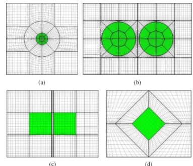
Fig. 2. Portion of the subdomain division profile in the computational domain near the cylinder scatterers (the colored region) for . (a) A single cir-cular cylinder. (b) Two coupled circir-cular cylinders. (c) Two coupled rectangular cylinders. (d) 45 -tilted square cylinder.
Fig. 2, the grid meshes based on the LGL points in each sub-domain, except the PML ones, are plotted for . As shown in the figure, the curved structure and the whole compu-tational region are partitioned into curvilinear subdomains, and LGL grid points are not uniformly distributed but somewhat following the outline of the domain edges. Please note that the LGL grid points at each edge side of a subdomain are colocated with the LGL grid points at one edge side of its adjacent subdomain. These colocated grid points are counted as distinct sets of points, and the penalty scheme is applied on the two sets for exchanging information of boundary conditions.
IV. NUMERICALRESULTS
Here, the PSFD method is applied to analyze some basic scat-tering problems. Accuracy will be first verified by examining a circular-metallic-cylinder problem and comparing the results with those obtained from the analytical approach. With the high accuracy provided, the PSFD method is then applied to simulate several coupled structures between closely placed, in nanometer scale, metallic cylinders and investigate their optical behaviors.
A. Single Circular Metallic Cylinder
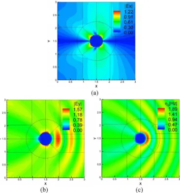
First, we examine the accuracy of the formulated Legendre PSFD method by solving a simple problem of TM scattering of a plane wave by a silver circular cylinder in free space at an optical wavelength. Such problem is known to have an an-alytical solution [27], [28]. Nevertheless, it is a good example to test how accurate a numerical analysis method can perform when dealing with plasmonic structures. The computational-do-main setup with PMLs and the subdocomputational-do-main division is as shown in Fig. 1, and the grid mesh is as depicted in Fig. 2(a). The ra-dius of the cylinder is m and the wavelength of the incident plane wave is m. At this wavelength, the
Fig. 3. Maximum absolute difference between the PSFD calculated field value and its corresponding analytical one scanned over the computational domain versus the degree of the Legendre polynomial used for the , and components, respectively, for TM scattering of a plane light wave at m by a silver circular cylinder of radius 0.25 m in free space.
measured complex dielectric constant of silver is about [34]. Fig. 3 shows the maximum absolute difference, , between the PSFD calculated field value and its corresponding analytical one scanned over the computational domain versus the degree of the Legendre polynomial used for the , and components, respectively, when the in-cident electric field intensity is 1 V/m, where refers to the field component. For , the difference in is considered, where is the free-space impedance. It is seen that the errors are on the order of when and on the order of
when and can get down to when . These
results demonstrate that our PSFD algorithm can provide high accuracy for solving light scattering by plasmonic structures. Also, the convergent plots show that the error exponentially, rather than linearly, decreases with respect to . This is the inherent characteristic of the spectral method having the con-vergent ratio proportional to . Fig. 4(a)–(c) plots the field profiles for , and , respectively, when the incident TM wave comes from right with po-larization. The computing resources used are described as fol-lows. For , and 12, the required matrix sizes are 31 164, 51 516, 76 956, and 107 484, respectively, the computer running times are 175, 429, 958, and 1970 s, respectively, and the memory usages are 9, 14, 20, and 27 Mb, respectively, exe-cuted by a single processing core on a personal computer with quad-core i7 3.42-GHz CPU in Linux environment. The compu-tation time approximately doubles as is increased by two, and the memory usages are not much. Note that the accuracy with can be more than what is required in practice since the error in the calculated field is on the order of as mentioned above.
In this verifying example of the PSFD method achieving such high accuracy, PML tuning is also an important process. From the given absorbing profile of PML, free parameters and can be varied to optimize the accuracy. According to our
Fig. 4. Field profiles for (a) , (b) , and (c) , respectively, for the case of Fig. 3, with the incident wave propagating from right to left.
experiences and in this case, the choices of and or 3 can provide better results as shown. This gives a gradually growing profile, and we adopt a wide PML with 3- m thickness for reducing reflection of waves.
B. The Single Dielectric Square Cylinder
Scattering of a 45 -tilted dielectric square cylinder investi-gated in [37] is considered next. The side length of the square
is , where is the free-space wavenumber,
and the plane wave incidence is as indicated in the inset of Fig. 5 with wavelength . Here, the dimensions are all normalized to according to [37], so the size of the dielectric cylinder is measured in terms of . Note that the square was as-sumed in [37] to have rounded corners with a radius of curvature but it is assumed to have sharp corners in our cal-culations. Thus, there would be four singular points expected at these sharp corners in our results. The tangential electric field of the TM case versus , where is the distance along the upper square surface from the left apex to the right apex, is shown in Fig. 5(a) and (b) for cylinders of dielectric constants
and , respectively. The calculations were done for from 12 up to 28. The results are seen to well agree with those of [37], even for smaller s. Notice that the fields at the sin-gular points, for example, grow up as the grid reso-lution (or ) increases. Here, we used only one subdomain for this square structure, and there are points along to . The field distributions with are depicted in Fig. 6. Because the incident wave comes from the left, the fields are seen to be longitudinally symmetric. The sin-gular points can be observed at the upper and bottom apexes in Fig. 6(b). To observe more clearly the singular-point char-acteristics, the expanded view of those results in Fig. 5(a) near is shown in Fig. 5(c). Note that, at , there
Fig. 5. Tangential electric field versus for (a) and (b) for the scattering of a 45 -tilted dielectric square cylinder with side length . The dots are adopted from [37] and other lines stand for PSFD calculated results of different degrees . (c) The expanded view of those results in (a) near together with the corresponding PSFD calculated total electric field results for showing the singular electric-field characteristic at the dielectric corners.
Fig. 6. Field profiles for (a) , (b) , and (c) , respectively, for the case of Fig. 5(b).
are two values for each since the tangential component value referring to the left side and that referring to the right side are different. Also displayed in Fig. 5(c) are the corresponding profiles for the magnitudes of the total electric field, , which show sharper singular behavior. The subdomain division profile near the square cylinder is plotted in Fig. 2(d).
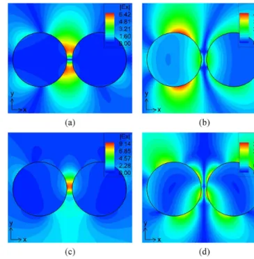
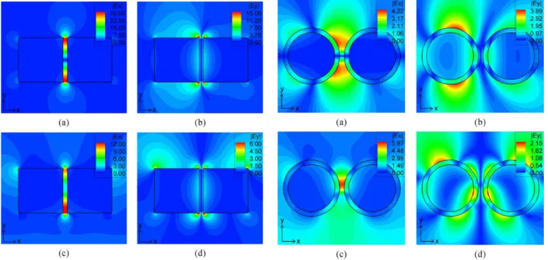
Fig. 7. and field distributions for plane-wave scattering by two cou-pled silver circular cylinders. The plane wave is incident from left in (a) and (b), and from bottom in (c) and (d). The radii are 50 nm and the side spacing between the two cylinders is 10 nm.
C. Two Coupled Circular Metallic Cylinders
The field coupling between metallic nanoparticles plays an important role in plasmonic research, which in particular may result in strong local-field enhancement that can provide many useful applications. We apply the PSFD method to study the phenomenon of field coupling between two silver nano-cylin-ders, with focus on two closely placed cylinders interacting with incident light waves of different directions and polarizations.
The first case is a system of two 50-nm-radius circular cylin-ders with 10-nm spacing allocated along the -axis. For the and distribution results shown in Fig. 7(a) and (b), the wave is incident from left at m and with polarization. The measured complex dielectric constant of silver at this wave-length is . The two cylinders are coupled such that strong electric field enhancement occurs within the gap be-tween them, with the maximum being about 6.42 times the incident electric field intensity, as indicated in the color bar in Fig. 7(a). Due to the direction of the incident wave, the elec-tric field profile is longitudinally symmeelec-tric with respect to the arrangement of cylinders. There is a null at the center, and the fields below and above it are oppositely signed in phase. Also, the incident polarization causes the first cylinder to oscillate with strong fields on both -ended surfaces, as depicted in Fig. 7(b), and less influence is on the second cylinder due to the shielding from the first cylinder.
If the propagation direction of the incident wave is changed to be bottom-up with polarization, strong field enhancement
occurs at m with the and field
distribu-tions shown in Fig. 7(c) and (d), respectively. At this wave-length, the measured complex dielectric constant of silver is about . In this case, obviously, the incident field leads the free electrons in both cylinders to oscillate hori-zontally and induces a strongly coupled field within the gap,
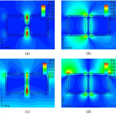
Fig. 8. and field distributions for plane-wave scattering by two cou-pled silver rectangular cylinders. The plane wave is incident from left in (a) and (b), and from bottom in (c) and (d). The edge length are 100 nm and the side spacing between the two cylinders is 10 nm.
which is about 9.14 times enhancement. Note that the maximum induced field is not exactly located right at the center, but about 5 nm upper. The induced field is transversely sym-metric and not strongly enhanced, and the phases of the two cylinders are reversed such that there also exists a null in between. It is seen in the above two situations that the plane wave incident from the bottom provides higher field enhance-ment than that from the left.
D. Two Coupled Square Metallic Cylinders
Next, we study the field coupling between two square metallic cylinders. Different from the circular ones, the square cylin-ders have four sharp corners, which would cause singular points and thus induce extremely, infinity theoretically, strong fields would exist around these apexes, causing challenges in numer-ical computations.
The simulated case is a system of two square cylinders, each having 100-nm edge width, again with 10-nm spacing. This structure is to be compared with the above one of circular cylin-ders. Fig. 8(a) and (b) shows the and distributions when the wave is incident from left at m. The complex dielectric constant of silver at this wavelength is about . From the field shown in Fig. 8(a), it re-veals two spots of field enhancement at the upper and lower corners in the gap, with the field enhancement being as high as up to 30 times. The calculated fields at the apexes would be even higher as is increased. As in the case of coupled circular cylinders, the profile is distributed mainly at both -ended edges of the first cylinder. The appearance of symmetric upper and lower field-enhancement regions is quite similar to those in Fig. 7(a) and (b).
Fig. 9. and field distributions for plane-wave scattering by two cou-pled silver circular cylinders having a dielectric coating of 10-nm thickness. The plane wave is incident from left in (a) and (b), and from bottom in (c) and (d).
Likewise, if we change the incident wave direction to
bottom-up at m, the strong enhancement
appears in the gap near the bottom corner, as shown in Fig. 8(c), due to the -polarized incident field, with the enhancement being up to 12 times, which is smaller than that in Fig. 8(a). The complex dielectric constant of silver at this wavelength is . Note that the field is now not enhanced at the center but near the bottom of the gap. Opposite field phases in Fig. 8(a) with respect to horizontal symmetric plane and in Fig. 8(d) with respect to the vertical symmetric plane in Fig. 8(d) cause obvious null-field appearances within the gap region.
E. Two Coupled Metallic Cylinders With Dielectric Coating
We further study the situations with each of the cylinders in Figs. 7 and 8 coated with a 10-nm-thickness dielectric layer of dielectric constant . We maintain the diameter or edge width of each silver cylinder, and the gap size is still kept as 10 nm. It is known that this outer dielectric material can make the plasmonic resonant frequency shifted, but the optical field characteristics are rarely seen, especially for coupled cylinders. The results corresponding to Fig. 7 are shown in Fig. 9 and those corresponding to Fig. 8 are shown in Fig. 10. The incident wave-lengths in Fig. 9(a)–(b), Fig. 9(c)–(d), and Fig. 10(a)–(b), and Fig. 10(c)–(d) are 0.467, 0.417, 0.649, and 0.616 m, respec-tively, with the corresponding complex dielectric constants of
, and
, respectively. The characteristics of and pro-files are seen to be quite similar with those in Figs. 7 and 8, but the localized fields now appear mainly at the dielectric-dielec-tric interfaces and in the gaps, which could reduce the ohmic losses in the metals. The field enhancement is found to be lower compared with uncoated cases, which can be explained by the
Fig. 10. and field distributions for plane-wave scattering by two cou-pled silver rectangular cylinders having a dielectric coating of 10-nm thickness. The plane wave is incident from left to right in (a) and (b) and from bottom in (c) and (d).
fact that the actual distance between the metallic cylinders is 30 nm rather than 10 nm.
F. Three Pairs of Circular Metallic Cylinders
We finally investigate two-by-three arranged six-silver-cylinder arrays studied in [10], where the FDTD method was used for simulations. This cylinder arrangement is shown to give not only particle-particle but pair-pair interactions, thus strong localized field enhancement could be generated in the gap of the middle pair [10]. In [10], measured material characteristics for silver given in [35] instead of [34] were used. We also adopt the data in [35] in our calculations for comparison. Our PSFD results given in Fig. 11 are for the incident wave from left to right and the spacing between ad-jacent cylinders being 20 nm. In [10], it was found that with gap size of 20 nm and at nm, the maximum field enhancement of about 8.89 occurs when the cylinder radius is 36 nm. Our PSFD simulated profile for this case is shown in Fig. 11(a), where the maximum field value is 11.11 V/m, referring to the incident field of 1 V/m, and the field value at the center of the gap of the middle pair is about 9.33 V/m, which is larger than that value of [10] by 4.72%. The value
is defined here by . The measured
complex dielectric constant of silver given in [35] is about at this wavelength. If the value given
in [34], , is used, the PSFD calculated
maximum field value and the field value at the center of the gap of the middle pair would be about 13.78 and 11.65 V/m, respectively.
When the wavelength is changed to 650 nm, the cylinder ra-dius was found in [10] to be 58 nm for generating largest field enhancement of 13.04. Our results for this case are presented
Fig. 11. field distributions for plane-wave scattering by six silver circular cylinders with incident wave from left. (a) Cylinder radius nm at 460 nm. (b) Cylinder radius 58 nm at nm. All gap widths are 20 nm.
in Fig. 11(b), where the maximum field is 15.54 V/m and the field value at the same gap center is about 14.09 V/m, again larger than those values of [10] by 8.05%. The complex dielec-tric constant of silver cylinder is about
from [35] for this incident wavelength. Again, if we choose to adopt the measured parameter from [34], which is
, the PSFD calculated maximum field value and the field value at the center of the gap of the middle pair would be about 17.07 V/m and 15.51 V/m, respectively.
V. SOME REMARKS ON THE PROPOSED FORMULATION ANDSCHEME
The proposed pseudospectral formulation and scheme in this paper have been based on the Legendre collocation points, the first-order Maxwell’s equations, and the penalty scheme for in-terface conditions, which are in contrast to some existing ones based on the Chebyshev collocation points, the second-order Helmholtz equations, and/or directly matching interface condi-tions. The advantages of our ones are discussed in the following.
A. Legendre Collocation Points Versus Chebyshev Collocation Points
A major factor, which makes the Chebyshev pseudospectral approximations based on the Chebyshev–Gauss–Lobatto points more popular than the Legendre pseudospectral approximations based on the Legendre–Gauss–Lobatto points, is the fast fourier transform (FFT). This technique allows the numerical deriva-tives to be computed in operations. Indeed, Cheby-shev pseudospectral method is very attractive for problems de-fined on regular domains, based on single domain computational framework. For these problems, either dependent or time-independent, if the required number of grid points is beyond 100, then the FFT technique does improve the computational ef-ficiency. However, in a multidomain computational framework which can be used to solve problems defined on complicated domains, the number of grid points in each subdomain is gen-erally much less than 100 and thus, we do not gain efficiency on using Chebyshev pseudospectral method [38]. Of course this does not mean we need to use Legendre pseudospectral method instead. The reason of using Legendre pseudospectral approx-imation will be discussed after addressing issues related to the penalty methodology of imposing boundary conditions.
B. Penalty Method for Interface Conditions and Directly Matching Interface Conditions
We now address issues related to the approaches of imposing boundary conditions. Generally speaking, an interface boundary condition is a constraint relating field values on both sides of the interface in a specific way, possibly involving differentia-tions and geometrical parameters. In the present study, the ge-ometrical parameter is the unit vector normal to the interface. In a multidomain computational framework, a problem domain is decomposed into a union of subdomains. Thus, at the sub-domain interfaces we need to enforce interface boundary con-ditions. As a consequence, it is necessary to specify a unique normal vector at every boundary grid point, and this becomes a problem at a vertex point of a 2-D subdomain. Is it possible to assign a unique normal vector at a vertex point? Or does it exist a unique normal vector at a vertex point? Frankly speaking, we have no answer to the problem and we doubt that there is an answer to the problem. Thus, this becomes a problem when we want to impose boundary condition through a directly matching approach at a location shared by vertex points of different sub-domains, and great care must be exercised to resolve this issue. In contrast, the penalty methodology offers an edge-by-edge ap-proach to impose boundary conditions [23], [39], [40]. It is not necessary to specify a unique normal vector at a vertex point, because a vertex point is an intersection of two boundary edges of a subdomain. Since we can specify normal vector functions along the edges of a subdomain, we define two normal vec-tors at a vertex point based on the normal vecvec-tors on the edges that intersect at the vertex. As a result, every vertex point is en-forced with two penalty boundary conditions with field values from two attached edges belonging to different subdomains. This does not ruin the consistency (accuracy) of the scheme at all. As we have shown in our numerical experiments, the results are exponentially convergent. This explains why we adopt the penalty methodology for imposing boundary conditions.
C. Why the Legendre Pseudospectral Method?
The penalty method incorporates numerical partial differ-ential equations and boundary conditions through a linear combination parameterized by a penalty parameter [23], [39]–[41]. The value of this parameter is commonly determined such that the scheme is stable in an energy sense. To conduct such an analysis, one needs to establish a discrete energy norm measurement. This issue makes Legendre pseudospec-tral method very attractive, because Legendre pseudospecpseudospec-tral method is equipped with a quadrature integration rule (Le-gendre–Gauss–Lobatto quadrature rule) which can be used to construct a discrete norm measurement for grid-functions [42]. The Chebyshev pseudospectral method also has a quadra-ture integration rule [42]. However, the rule does not coincide with the usual energy norm measurements for functions. Using the Legendre–Gauss–Lobatto quadrature rule to conduct an energy estimate, one can determine the value of the penalty parameter to ensure the stability of a scheme in a theoretical basis, instead of a trial-and-error basis. This procedure is useful and important, because high-order accurate numerical methods, compared to the low-order accurate ones, are very sensitive to the impositions of boundary conditions [42], [43]. For time-de-pendent problems, if boundary conditions are not imposed
properly, it often causes numerical blow-up solutions because of numerical instability inducing from subdomain boundaries. For time-independent or time-harmonic problems, improper impositions of boundary conditions may cause non-convergent solutions during iteration processes. Roughly speaking, these instabilities and nonconvergence problems are often resulting from numerical solution operators being unstable, in the sense that some eigenvalues of the solution operators have posi-tive real part, commonly due to the impositions of boundary conditions. To avoid these unwanted situations, constructing a energy stable scheme in the theoretical stage becomes important in building a multidomain computational framework for simulations. Thus, based on the above arguments we adopt the Legendre pseudospectral method instead of the Chebyshev pseudospectral methods.
D. Why First-Order Maxwell’s Equations Instead of Second-Order Helmholtz Equations?
In the present study, we solve first-order system Maxwell’s equations instead of the equivalent second-order Helmholtz equations. This approach, indeed, is a drawback of the present formulation because it requires to solve more equations. In 2-D space, three coupled first-order partial differential equations need to be solved but only one equation to be solved if the problem is described by the second-order Helmholtz equation. However, the present first-order system formulation can be directly extended for waves in anisotropic media, even possibly with permittivity or permeability of media being a tensor. It is because the material parameters are not associated with the curl operator parts [23], [40]. Thus, we do not need to reformulate the penalty boundary condition formulations. As mentioned earlier, the penalty type boundary formulations avoid the ambi-guity of specifying normal vectors at subdomain vertex points and this simplifies the imposing of interface boundary condi-tions. Of course, it would be even more attractive to construct pseudospectral penalty schemes for Helmholtz equations di-rectly. A possible way is first identifying well-posed boundary operators for vectorial second-order wave equations which are the time-domain representation of Helmholtz equations. Once the well-posed operators for the second-order wave equations are identified, a pseudospectral penalty scheme may be for-mulated for the second-order wave equations. We can then easily convert the time-domain scheme to frequency-domain equations, which becomes a pseudospectral penalty scheme for the equivalent Helmholtz equations. We are putting our effort on this subject and hope to report the results in the future.
VI. CONCLUSION
A multidomain PSFD method has been developed based on the Legendre polynomials and a penalty scheme for solving Maxwell’s equations. The application is particularly aimed at electromagnetic wave scattering problems in plasmonics with the goal of obtaining high-accuracy near fields. Calculation of light scattering by a silver circular cylinder has demonstrated that this PSFD method indeed provides high-order accuracy with the obtained field error down to referring to 1-V/m incident electric field strength, thanks to the spectral conver-gence property of the spectral method and the accurate fulfill-ment of the field continuity conditions across the material inter-faces provided by the multidomain approach as well as global
interpolation by Legendre polynomials. In the multidomain ap-proach, the whole computational domain is properly partitioned into curvilinear subdomains fitting the generally curved mate-rial-interface shapes. With this demonstrated extremely high nu-merical accuracy, the formulated method should be useful for plasmonics research and can provide reliable results for the cal-culation of field enhancement near metal surface, as shown in the numerical examples including coupled plasmonic cylinders of either circular or square shape. Our analysis results also pro-vide a good reference for other numerical methods to compare with. Moreover, the frequency-domain approach has the advan-tage of directly using a given complex dielectric constant of the material in the calculation with no need of implementing a dis-persive material model like in the time-domain approach.
A final remark goes to the possible singular-field behavior when the material interface is non-smooth such as in the square-shaped-cylinder cases, as was discussed in connection with Fig. 5. Although the spectral convergence property of the PSFD method has been demonstrated when simulating round cylinders, when interface corners appear, numerical convergence would unavoidably be degraded. In Fig. 5(c), it was demonstrated that, although only one subdomain is em-ployed for the square-cylinder cross-section, the singular-field characteristic evolves as the degree in the PSFD calculation is increased so that the grid size near the dielectric corner shrinks. Related treatment of such singularities based on the finite element method has been reported through using al-gebraically graded grids near the corner where a singularity exists [38]–[40]. Further treatment and more detailed study about the corner singularities using the PSFD method, such as with refined arrangement of subdomains, would worth being pursued as a more basic topic.
ACKNOWLEDGMENT
The authors would like to thank the National Center for High-Performance Computing, Hsinchu, Taiwan, the Academia Sinica Computing Center, Taipei, Taiwan, and the Computer and Information Networking Center, National Taiwan Univer-sity, Taipei, for providing useful computing resources.
REFERENCES
[1] S. A. Maier and H. A. Atwater, “Plasmonics: Localization and guiding of electromagnetic energy in metal/dielectric structures,” J. Appl. Phys., vol. 98, no. 1, Jul. 2005, Art. ID 011101.
[2] M. Moskovits, “Surface-enhanced spectroscopy,” Rev. Mod. Phys., vol. 57, no. 3, pp. 783–826, July 1985.
[3] P. Mühlschlegel, H. J. Eisler, O. J. F. Martin, B. Hecht, and D. W. Pohl, “Resonant optical antennas,” Science, vol. 308, pp. 1607–1609, 2005. [4] S. A. Maier, P. G. Kik, and H. A. Atwater, “Optical pulse propagation in metal nanoparticle chain waveguides,” Phys. Rev. B, vol. 67, p. 205402, 2003.
[5] J. P. Kottmann and O. J. F. Martin, “Retardation-induced plasmon resonances in coupled nanoparticles,” Opt. Lett., vol. 26, no. 14, pp. 1096–1098, July 2001.
[6] C. F. Bohren and D. R. Huffman, Absorption and Scattering of Light by Small Particles. New York: Wiley, 1983.
[7] R. L. Chern, X. X. Liu, and C. C. Chang, “Particle plasmons of metal nanospheres: Application of multiple scattering approach,” Phys. Rev. E, vol. 76, 2007, Art. ID 016609.
[8] R. Gomez-Medina, M. Laroche, and J. J. Saenz, “Extraordinary optical reflection from sub-wavelength cylinder arrays,” Opt. Exp., vol. 14, no. 9, pp. 3730–3737, May 2006.
[9] A. Taflove and S. C. Hagness, Computational Electrodynamics: The Finite-Difference Time-Domain Method, 3rd ed. Norwood, MA: Artech House, 2005.
[10] M. Y. Ng and W. C. Liu, “Local-field confinement in three-pair arrays of metallic nanocylinders,” Opt. Exp., vol. 14, no. 10, pp. 4504–4513, May 2006.
[11] J. P. Kottmann and O. J. F. Martin, “Plasmon resonant coupling in metallic nanowires,” Opt. Exp., vol. 8, no. 12, pp. 655–663, Jun. 2001. [12] M. W. Chen, Y. F. Chau, and D. P. Tsai, “Three-dimensional analysis of scattering field interactions and surface plasmon resonance in cou-pled silver nanospheres,” Plasmonics, vol. 3, pp. 157–164, Oct. 2008. [13] R. Rodriguez-Oliveros and J. A. Sanchez-Gil, “Localized sur-face-plasmon resonances on single and coupled nanoparticles through surface integral equations for flexible surfaces,” Opt. Exp., vol. 19, no. 13, pp. 12208–12219, Jun. 2011.
[14] J. P. Kottmann, O. J. F. Martin, D. R. Smith, and S. Schultz, “Plasmon resonances of silver nanowires with a nonregular cross section,” Phys. Rev. B, vol. 64, 2001, Art. ID 235402.
[15] E. Prodan, C. Radloff, N. J. Halas, and P. Nordlander, “A hybridization model for the plasmon response of complex nanostructures,” Science, vol. 302, no. 5644, pp. 419–422, Oct. 2003.
[16] B. Yang, D. Gottlieb, and J. S. Hesthaven, “Spectral simulations of electromagnetic wave scattering,” J. Comput. Phys., vol. 134, pp. 216–230, 1997.
[17] B. Yang and J. S. Hesthaven, “A pseudospectral method for time-do-main computation of electromagnetic scattering by bodies of revolu-tion,” IEEE Trans. Antennas Propagat., vol. 47, no. 1, pp. 132–141, Jan. 1999.
[18] J. S. Hesthaven, P. G. Dinesen, and J. P. Lynov, “Spectral colloca-tion time-domain modeling of diffractive optical elements,” J. Comput. Phys., vol. 155, pp. 287–306, Nov. 1999.
[19] G. Zhao and Q. H. Liu, “The 3-D multidomain pseudospectral time-domain algorithm for inhomogeneous conductive media,” IEEE Trans. Antennas Propagat., vol. 52, no. 3, pp. 742–749, Mar. 2004. [20] Q. H. Liu, “A pseudospectral frequency-domain (PSFD) method for
computational electromagnetics,” IEEE Antennas Wireless Propagat. Lett., vol. 1, pp. 131–134, 2002.
[21] P. J. Chiang, C. P. Yu, and H. C. Chang, “Analysis of two-dimensional photonic crystals using a multidomain pseudospectral method,” Phys. Rev. E, vol. 75, Feb. 2007, Art. ID 026703.
[22] P. J. Chiang, C. L. Wu, C. H. Teng, C. S. Yang, and H. C. Chang, “Full-vectorial optical waveguide mode solvers using multidomain pseudospectral frequency-domain (PSFD) formulations,” IEEE J. Quantum Electron., vol. 44, no. 1, pp. 56–66, Jan. 2008.
[23] C. H. Teng, B. Y. Lin, H. C. Chang, H. C. Hsu, C. N. Lin, and K. A. Feng, “A Legendre pseudospectral penalty scheme for solving time-domain Maxwell’s equations,” J. Sci. Comput., vol. 36, pp. 351–390, 2008.
[24] J. P. Berenger, “A perfectly matched layer for the absorption of elec-tromagnetic waves,” J. Comput. Phys., vol. 114, no. 2, pp. 185–200, Oct. 1994.
[25] S. Abarbanel and D. Gottlieb, “A mathematical analysis of the PML method,” J. Comput. Phys., vol. 134, pp. 357–363, 1997.
[26] S. Abarbanel and D. Gottlieb, “On the construction and analysis of absorbing layers in CEM,” Appl. Numer. Math., vol. 27, pp. 331–340, 1998.
[27] L. Rayleigh, “The dispersal of light by a dielectric cylinder,” Philos. Mag., vol. 36, pp. 365–376, 1918.
[28] J. R. Wait, “Scattering of plane wave from a circular dielectric cylinder at oblique incidence,” Can. J. Phys., vol. 33, no. 5, pp. 189–195, 1955. [29] W. J. Gordon and C. A. Hall, “Transfinite element methods: Blending function interpolation over arbitrary curved element domains,” Numer. Math., vol. 21, pp. 109–129, 1973.
[30] S. Dey and R. Mittra, “A locally conformal finite-difference time-do-main (FDTD) algorithm for modeling three-dimensional perfectly conducting objects,” IEEE Microw. Guided Wave Lett., vol. 7, pp. 273–275, Sept. 1997.
[31] Y. Liu, C. D. Sarris, and G. V. Eleftheriades, “Triangular-mesh-based FDTD analysis of two-dimensional plasmonic structures supporting backward waves at optical frequencies,” J. Lightw. Technol., vol. 25, no. 3, pp. 938–946, Mar. 2007.
[32] Y. Zhao and Y. Hao, “Finite-difference time-domain study of guided modes in nano-plasmonic waveguides,” IEEE Trans. Antennas Prop-agat., vol. 55, no. 11, pp. 3070–3077, Nov. 2007.
[33] W. J. Gordon and C. A. Hall, “Transfinite element methods: Blending-function interpolation over arbitrary curved element domains,” Numer. Math., vol. 21, pp. 109–129, 1973.
[34] P. B. Johnson and R. W. Christy, “Optical constants of the noble metals,” Phys. Rev. B, vol. 6, no. 12, pp. 4370–4379, Dec. 15, 1972. [35] E. D. Palik, Handbook of Optical Constants of Solids. New York:
Academic, 1985.
[36] N. N. Rao, Elements of Engineering Electromagnetics, 6th ed. Upper Saddle River, NJ: Prentice-Hall, 2004.
[37] J. B. Andersen and V. V. Solodukhov, “Field behavior near a dielectric wedge,” IEEE Trans. Antennas Propagat., vol. 26, no. 4, pp. 598–602, Jul. 1978.
[38] W. S. Don and A. Solomonoff, “Accuracy and speed in computing the Chebyshev collocation derivative,” SIAM J. Sci. Comput., vol. 16, no. 6, pp. 1253–1268, 1995.
[39] J. S. Hesthaven, “A stable penalty method for the compressible Navier-Stokes equations: III. Multidimensional domain decomposi-tion schemes,” SIAM J. Sci. Comput., vol. 20, no. 1, pp. 62–93, 1998. [40] J. S. Hesthaven and T. Warburton, “Nodal high-order methods on
un-structured grids: I. Time-domain solution of Maxwell’s equations,” J. Comput. Phys., vol. 181, pp. 186–221, 2002.
[41] D. Funaro and D. Gottlieb, “A new method of imposing boundary-conditions in pseudospectral approximations of hyperbolic-equations,” Math. Computation, vol. 51, pp. 599–613, 1988.
[42] J. S. Hesthaven, S. Gottlieb, and D. Gottlieb, Spectral Methods for Time-Dependent Problems. Cambridge, U.K.: Cambridge Univ., 2007.
[43] D. Gottlieb, M. Gunzburger, and E. Turkel, “On numerical boundary treatment of hyperbolic systems for finite difference and finite element methods,” SIAM J. Numer. Anal., vol. 19, no. 4, pp. 671–681, 1982. [44] T. Apel and S. Nicaise, “The finite element method with anisotropic
mesh grading for elliptic problems in domains with corners and edges,” Math. Methods Appl. Sci., vol. 21, pp. 519–549, 1998.
[45] T. Apel, A.-M. Sandig, and J. R. Whiteman, “Graded mesh refinement and error estimates for finite element solutions of elliptic boundary value problems in non-smooth domains,” Math. Methods Appl. Sci., vol. 19, pp. 63–85, 1996.
[46] K. Schmidt and P. Kauf, “Computation of the band structure of two-dimensional photonic crystals with HP finite elements,” Comput. Methods Appl. Mech. Eng., vol. 198, pp. 1249–1259, 2009.
Chih-Yu Wang received the B.S. degree from the Department of Engineering
Science, National Cheng Kung University, Taiwan, in 2004, and the M.S. and Ph.D. degrees from the Graduate Institute of Electronics Engineering, National Taiwan University, Taiwan, in 2006 and 2012, respectively.
Her current research interests include the pseudospectral electromagnetics modeling in frequency domain.
Shih-Yung Chung received the B.S. degree from the Department of Electrical
Engineering, National Cheng Kung University, Tainan, Taiwan, in 2004, and the M.S. and Ph.D. degrees from the Graduate Institute of Electronics Engineering, National Taiwan University, Taipei, Taiwan, in 2006 and 2012, respectively.
His current research interests include the electromagnetic simulations using the pseudospectral time-domain method.
Chun-Hao Teng was born in Tainan, Taiwan, on February 14, 1970. He
re-ceived the diploma in mechanical engineering from National Taipei Institute of Technology, Taipei, Taiwan, in 1990, the M.S. degree in mechanical engineering from Clarkson University, Potsdam, NY, in 1996, and the M.S. and Ph.D. de-grees in applied mathematics from Brown University, Providence, RI, in 2001. From 2003 to 2009, he was an Assistant Professor with the Department of Mathematics, National Cheng Kung University, Tainan, Taiwan. He is currently an Assistant Research Fellow with the Center of Mathematical Modeling and Scientific Computing, National Chiao Tung University, Hsinchu, Taiwan. His research interests are the developments and applications of high-order numerical methods for partial differential equations.
Juen-Kai Wang was born in Tainan, Taiwan, on July 9, 1961. He received the
B.S. degree in electrical engineering from National Taiwan University, Taipei, Taiwan, in 1983, and the M.S. and Ph.D. degrees in applied physics from Har-vard University, Cambridge, MA, in 1986 and 1992, respectively.
From 1992 to 1994, he was with Arthur Amos Noyes Laboratory of Chemical Physics, California Institute of Technology, Pasadena. In December 1994, he joined the faculty of the Center for Condensed Matter Sciences, National Taiwan University, Taipei, Taiwan, where he is currently a Research Fellow. He is also jointly appointed with the Institute of Atomic and Molecular Sciences (IAMS) of Academia Sinica. He has acted as a consultant to Industrial Technology Research Institute since 2002. His current research interests include nanometer-scaled optical spectroscopy, ultrafast laser spectroscopy, surface-enhanced Raman spectroscopy, plasmonics, surface vibrational spec-troscopy, biomedical vibrational specspec-troscopy, physical studies of organic semiconductors and their photovoltaic applications, and intense laser interac-tion with matters.
Dr. Wang was the recipient of the Executive Yuan Award for Outstanding Contributions in Science and Technology in 2009 and the Nano-Tech Award in 2010 that he shared with Dr. Yuh-Lin Wang of IAMS and Prof. Chi-Hung Lin of National Yang-Ming University for their contribution in developing high-speed detection technology for microbiology.
Chung-Ping Chen (M’96) received the B.S. degree in computer science and
in-formation engineering from National Chiao-Tung University, Hsinchu, Taiwan, in 1990, and the M.S. and Ph.D. degrees in computer science from the Univer-sity of Texas, Austin, in 1996 and 1998, respectively.
From 1996 to 1999, he was with Strategic Computer-Aided Design (CAD) Labs, Intel Corporation, Hillsboro, OR, as a Senior CAD Engineer. Since 1999, he has been an Assistant Professor with the Department of Electrical and Com-puter Engineering, University of Wisconsin, Madison. Since 2003, he has been an Associate Professor with the Electrical Engineering Department, National Taiwan University, Taipei, Taiwan. Currently, he is a Professor with the Grad-uate Institute of Electronics Engineering, Biomedical Electronics and Bioinfor-matics and Electrical Engineering Departments, National Taiwan University. His research interests include the areas of electronic design automation and BIO topics, including computer-aided design and microprocessor circuit design with an emphasis on interconnect and circuit optimization, circuit simulation, statis-tical design, and signal/power/thermal integrity analysis and optimization.
Dr. Chen was the recipient of the D2000 Award from Intel Corporation and the National Sciences Foundation Faculty Early Career Development awards (CAREER) from 1999 to 2001, respectively. He also received the 2002 Special Interest Group on Design Automation/ACM Outstanding Young Faculty Award and the 2002 IBM Peter Schneider Faculty Development Award. He served the program committee and is an organizer of the Design Automation Conference, the International Conference on Computer-Aided Design, Design, Automation, and the Test in Europe Conference, the International Symposium on Physical Design, the Asia and South Pacific Design Automation Conference, the Inter-national Symposium on Quality Electronic Design, Synthesis and System Inte-gration of Mixed Information, the VLSI/CAD Symposium, and the International Technology Roadmap for Semiconductors Conference.
Hung-Chun Chang (S’78–M’83–SM’00) was born in Taipei, Taiwan, on
Feb-ruary 8, 1954. He received the B.S. degree from National Taiwan University, Taipei, Taiwan, in 1976, and the M.S. and Ph.D. degrees from Stanford Univer-sity, Stanford, CA, in 1980 and 1983, respectively, all in electrical engineering. From 1978 to 1984, he was with the Space, Telecommunications, and Ra-dioscience Laboratory of Stanford University. In August 1984, he joined the faculty of the Electrical Engineering Department, National Taiwan University, Taipei, Taiwan, where he is currently a Distinguished Professor. He was the NTU Himax Chair Professor during 2011. He served as Vice-chairman of the EE Department from 1989 to 1991, and Chairman of the newly established Grad-uate Institute of Electro-Optical Engineering at the same university from 1992 to 1998. His current research interests include the electromagnetic theory, design, and application of photonic structures and devices for fiber optics, integrated optics, optoelectronics, nanophotonics, and plasmonics.
Dr. Chang is a Fellow of the Optical Society of America and the Electromag-netics Academy. He served as the IEICE (Japan) Overseas Area Representative in Taipei from 2002 to 2007.
A Multidomain Pseudospectral Mode Solver for
Optical Waveguide Analysis
Shun-Fan Chiang, Bang-Yan Lin, Hung-Chun Chang, Senior Member, IEEE, Fellow, OSA, Chun-Hao Teng,
Chih-Yu Wang, and Shih-Yung Chung
Abstract—We propose a pseudospectral mode solver for optical
waveguide mode analysis formulated by the frequency-domain Maxwell equations. Special attention is paid upon identifying the required boundary operator for the formulation and the relationships between the derived operator and the physical boundary conditions. These theoretical results are adopted into a Legendre pseudospectral multidomain computational framework to compute the propagation characteristics of optical waveguides. Numerical experiments are conducted, and the expected spectral convergence of the scheme is observed for smooth problems and for problems having field jumps at material interfaces. For dielec-tric waveguides with sharp corners, the spectral convergence is lost due to the singular nature of fields at the corner. Nevertheless, compared with other methods, the present formulation remains as an efficient approach to obtain waveguide modes.
Index Terms—Frequency-domain Maxwell’s equations,
op-tical waveguides, penalty boundary conditions, pseudospectral methods, waveguide analysis.
I. INTRODUCTION
I
N modal analysis for optical waveguides, the propagation constants and the associated field distributions of guided modes provide useful information in designing and operating optical guiding devices such as filters, switches, modulators, and fibers. To obtain these guiding characteristics, one needs to solve either Maxwell’s equations or the vectorial HelmholtzManuscript received January 19, 2012; revised March 13, 2012; accepted March 17, 2012. Date of publication March 23, 2012; date of current version April 27, 2012. This work was supported in part by the National Science Council of Taiwan under Grant NSC99-2115-M-009-012-MY3, Grant NSC97-2221-E-002-043-MY2, and Grant NSC99-2221-E-002-107-MY2, the Excellent Research Projects of National Taiwan University under Grant 10R80919-1, and the Ministry of Education of Taiwan under The Aim of Top University Plan Grant. The work of C.-H. Teng was supported by the National Science Council of Taiwan under Research Fellow Program NSC099-2811-M-009-047 and NSC100-2811-M-009-055.
S.-F. Chiang was with the Graduate Institute of Photonics and Optoelec-tronics Engineering, National Taiwan University, Taipei 10617, Taiwan. He is now with Hon Hai Precision Industry Company Ltd., Taipei 20306, Taiwan (e-mail: [email protected]).
B.-Y. Lin was with the Graduate Institute of Communication Engineering, National Taiwan University, Taipei 10617, Taiwan. He is now with Taiwan Semiconductor Manufacturing Company, Hsinchu 30077, Taiwan (e-mail: [email protected]).
H.-C. Chang is with the Department of Electric Engineering, National Taiwan University, Taipei 10617, Taiwan (e-mail: [email protected]).
C.-H. Teng is with the Department of Applied Mathematics and the Center of Mathematical Modeling, National Chiao Tung University, Hsinchu 30010, Taiwan (e-mail: [email protected]).
C.-Y. Wang and S.-Y. Chung are with the Graduate Institute of Electronics Engineering, National Taiwan University, Taipei 10617, Taiwan (e-mail: [email protected]; [email protected]).
Digital Object Identifier 10.1109/JLT.2012.2191937
equations, subject to boundary conditions. However, due to the involved mathematical difficulties raised from either the geom-etry configurations of devices or the heterogeneous distribu-tions of material properties, waveguide problems are in general very hard to solve analytically. For realistic cases, numerical methods are employed to obtain the guiding characteristics.
Among numerical methods, Cartesian finite difference methods [1]–[6] are popular for waveguide problems if the geometry of the guiding structure is confined to the grid lines. However, for problems involving curved interfaces, special dif-ference stencils are required to treat field values in the vicinity of curved interfaces to maintain accurate computations [7]–[9]. Also commonly used in modal analysis, body-fitted finite element methods [10]–[13] adopt unstructured and structural meshes to fit the geometries and employ edge elements and tangential elements to discretize the equations and boundary conditions. Most of the aforementioned methods are low-order accurate methods, typically first or second order. As the com-plexity of waveguide problems increases, these finite difference and finite element schemes require using dense meshes to perform accurate computations. Hence, these approaches lead to large systems of equations to be solved, which may consume lots of computational resources and time. An approach for overcoming this issue is designing high-order accurate schemes based on spectral/pseudospectral methods [14]–[17]. Gener-ally, these schemes can compute accurate results by using a coarse mesh, compared to low-order methods. However, this advantage does not come along freely, and great care must be exercised to ensure the high-order convergence rate, because these methods are very sensitive to the smoothness of the solutions and the imposition of boundary conditions [18].
In this study, we present a high-order accurate and geomet-rically flexible computational approach for waveguide mode analysis. Unlike the mentioned pseudospectral approaches that adopt the vectorial Helmholtz equations as the main equations, we consider the frequency-domain Maxwell’s equations as the governing equations. Special attention is paid upon analyzing the required boundary operator for the frequency-domain Maxwell’s equations and its relationships with the common physical boundary conditions. These analytic results are then adopted into a multidomain pseudospectral computational framework through the penalty methodology [19]–[22]. The proposed formulation is validated through computing the propagation characteristics of fundamental modes of a number of waveguide structures. We observe the expected spectral convergence results for smooth waveguide problems and for problems having finite jumps of fields at material interfaces. However, for dielectric waveguides having sharp corners, it is found that the spectral convergence is lost, due to the singular 0733-8724/$31.00 © 2012 IEEE