利用數位浮水印與影像驗證作影像版權保護及竄改偵測之研究
118
0
0
全文
(2) 利用數位浮水印與影像驗證作影像版權保護及竄改偵測之研究 A Study on Digital Watermarking and Authentication of Images for Copyright Protection And Tampering Detection. 研 究 生:邱彥中. Student:Yen-Chung Chiu. 指導教授:蔡文祥. Advisor:Wen-Hsiang Tsai. 國 立 交 通 大 學 資 訊 科 學 研 究 所 碩 士 論 文. A Thesis Submitted to Institute of Computer and Information Science College of Electrical Engineering and Computer Science National Chiao Tung University in partial Fulfillment of the Requirements for the Degree of Master in. Computer and Information Science June 2004 Hsinchu, Taiwan, Republic of China. 中華民國九十三年六月.
(3) 利用數位浮水印與影像驗證作影像版權保護及竄改偵 測之研究 研究生:邱彥中. 指導教授:蔡文祥 博士. 國立交通大學資訊科學研究所. 摘要. 由於數位科技的進步,數位影像可能會被非法複製,甚至是竄改。因此,發 展數位影像版權保護的方法是很重要的課題。在本論文中,針對這個目的,我們 提出了數種數位浮水印的技術。數位浮水印必須具有強韌性來抵抗非法使用者對 影像的各種操作。針對彩色影像,我們提出了四種方法分別來抵抗不同的攻擊。 首先,利用在離散富利葉轉換頻域上產生環狀和對稱的峰值來抵抗旋轉和縮放的 攻擊。第二,應用離散富利葉轉換和離散餘弦轉換兩個頻域來抵抗旋轉和裁切的 攻擊。第三,我們提出了一種在離散富利葉轉換頻域上,利用一個組合函數來對 峰值位置作編碼,此方法可用來抵抗影像列印和再掃描成數位影像的操作。第 四,是利用一種重新縮放影像的技術來抵抗縮放和行列移除的攻擊。最後,我們 也提出一種彩色影像驗證的方法,來證明影像的真實性和完整性。藉由檢查藏入 影像中的驗證信號,我們可以指出影像被竄改之處。利用藏入驗證信號來作影像 驗證的方法,可以不用另外存有一個影像特徵資料。相關的實驗結果證明所提方 法是可行性的。. i.
(4) A Study on Digital Watermarking and Authentication of Images for Copyright Protection And Tampering Detection Student: Yen-Chung Chiu. Advisor: Dr. Wen-Hsiang Tsai. Institute of Computer and Information Science National Chiao Tung University. ABSTRACT Due to the advance of digital techniques, digital images may be copied or tampered with illegally. Therefore, it is important to develop methods to protect the copyright of digital images and verify their integrity. In this study, digital watermarking techniques for such purposes are proposed. In addition, the watermark must have an ability of robustness because users may apply various operations on a watermarked image. For color images, four methods are proposed to handle different attacks. First, a method based on creating peaks circularly and symmetrically in the DFT domain is proposed to resist rotation and scaling attacks. Second, a watermarking method utilizing the DFT and DCT domains is proposed to survive rotation and cropping attacks. Third, a method based on coding peaks by a combinatorial function in the DFT domain is proposed to work against print-and-scan operations. Fourth, a method based on an image rescaling technique is proposed to resist scaling and line-removal attacks. Finally, an authentication method for verifying the fidelity and integrity of color images is also proposed, which uses a key to generate authentication signals randomly. By checking authentication signals in an image, tampered parts can be pointed out. Such authentication signals can be used to conduct the authentication work without using other signature data. Good experimental results prove the feasibility of the proposed methods.. ii.
(5) ACKNOWLEDGEMENTS. The author is in hearty appreciation of the continuous guidance, discussions, support, and encouragement received from his advisor, Dr. Wen-Hsiang Tsai, not only in the development of this thesis, but also in every aspect of his personal growth. Thanks are due to Mr. Chih-Hsuan Tzeng, Mr. Chang-Chou Lin, Mr. Chih-Jen Wu, Mr. Tsung-Yuan Liu, Mr. Wei-Liang Lin, Mr. Yi-Chieh Chen, Mr. Kuei-Li Huang, Mr. Cheng-Jyun Lai, Miss Yen-Lin Chen, and Mr. Nan-Kun Lo for their valuable discussions, suggestions, and encouragement. Appreciation is also given to the colleagues of the Computer Vision Laboratory in the Department of Computer and Information Science at National Chiao Tung University for their suggestions and help during his thesis study. Finally, the author also extends his profound thanks to his family for their lasting love, care, and encouragement. He dedicates this dissertation to his parents.. iii.
(6) CONTENTS ABSTRACT (in Chinese) ......................................................................... i ABSTRACT (in English)......................................................................... ii ACKNOWLEDGEMENTS ................................................................... iii CONTENTS............................................................................................. iv LIST OF FIGURES ............................................................................... vii LIST OF TABLES.................................................................................... x Chapter 1 Introduction ......................................................................... 1 1.1 1.2. Motivation....................................................................................................1 Review of Related Works ............................................................................2 1.2.1 Digital Watermarking against Geometric Attacks ..............................2 1.2.2 Digital Watermarking against Print-And-Scan Attacks ......................3 1.2.3 Digital Image Authentication..............................................................4 1.3 Overview of Proposed Methods...................................................................4 1.3.1 Definitions of Terms ...........................................................................4 1.3.2 Brief Descriptions of Proposed Methods............................................5 1.4 Thesis Organization ...................................................................................11. Chapter 2 Copyright Protection by Watermarking for Color Images against Rotation and Scaling Attacks Using Peak Detection and Synchronization in DFT Domain ............ 13 2.1 2.2. Introduction................................................................................................13 Ideas of Proposed Method .........................................................................14 2.2.1 Properties of Coefficients in the DFT Domain .................................14 2.2.2 Properties of Color Channels ............................................................16 2.2.3 Proposed Technique for Coding Peak Locations for Watermarking.17 2.2.4 Proposed Technique for Synchronizing Peak Locations for Protection against Rotation and Scaling Attacks................................................19 2.3 Watermark Embedding Process .................................................................20 2.3.1 Embedding of Watermarks................................................................20 2.3.2 Detailed Algorithm............................................................................21 2.4 Watermark Extraction Process ...................................................................24 2.4.1 Extraction of Watermarks .................................................................24 iv.
(7) 2.4.2 Detailed Algorithm............................................................................25 2.5 Experimental Results .................................................................................28 2.6 Discussions And Summary ........................................................................32. Chapter 3 Copyright Protection by Watermarking for Color Images against Rotation And Cropping Attacks Using Synchronization of Peak Locations in DFT Domain And Coefficient Relationship Comparison in DCT Domain. 34 3.1. Introduction................................................................................................35 3.1.1 Problem Definition............................................................................35 3.1.2 Review of Employed Techniques .....................................................36 3.2 Ideas of Proposed Method .........................................................................37 3.2.1 Proposed Technique for Multiply Embedding Watermark in DCT domain for Preventing Cropping Attack ...........................................38 3.2.2 Proposed Technique for Hiding Verification Code in DCT Domain. 3.3. 3.4. 3.5 3.6. for Watermark Existence Check .......................................................39 3.2.3 Proposed Technique for Hiding Synchronization Peak in DFT Domain to Detect Rotated Angle ......................................................40 Watermark Embedding Process .................................................................40 3.3.1 Embedding of Watermarks................................................................41 3.3.2 Detailed Algorithm............................................................................42 Watermark Extraction Process ...................................................................43 3.4.1 Extraction of Watermarks .................................................................43 3.4.2 Detailed Algorithm............................................................................45 Experimental Results .................................................................................48 Discussions And Summary ........................................................................51. Chapter 4 Copyright Protection by Watermarking for Color Images against Print-and-Scan Operations Using Coding and Synchronization of Peak Locations in DFT Domain ..... 53 4.1. Introduction................................................................................................53 4.1.1 Properties of Images Applied Print-and-Scan Operations ................54 4.1.2 Problem Definition............................................................................54 4.2 Ideas of Proposed Method .........................................................................55 4.2.1 Proposed Technique for Coding Peak Locations for Watermarking.55 4.2.2 Proposed Technique for Automatically Adjusting Threshold Value for Extracting Watermark .......................................................................56 4.3 Watermark Embedding Process .................................................................57 4.3.1 Embedding of Watermarks................................................................57 4.3.2 Detailed Algorithm............................................................................58 v.
(8) 4.4. Watermark Extraction Process ...................................................................59 4.4.1 Extraction of Watermarks .................................................................61 4.4.2 Detailed Algorithm............................................................................62 4.5 Experimental Results .................................................................................63 4.6 Discussions And Summary ........................................................................67. Chapter 5 Copyright Protection by Watermarking for Color Images against Scaling And Line-Removal Attacks Using An Image Rescaling Technique .............................................. 69 5.1. Introduction................................................................................................69 5.1.1 Review of Employed Techniques .....................................................70 5.1.2 Problem Definition............................................................................70 5.2 Brief Description of Proposed Idea for Rescaling Technique....................71 5.3 Watermark Embedding Process .................................................................72 5.3.1 Embedding of Watermarks................................................................72 5.3.2 Detailed Algorithm............................................................................73 5.4 Watermark Extraction Process ...................................................................75 5.4.1 Extraction of Watermarks .................................................................75 5.4.2 Detailed Algorithm............................................................................75 5.5 Experimental Results .................................................................................79 5.6 Discussions And Summary ........................................................................84. Chapter 6 Tampering Detection in Color Images by Signature-Free Authentication Using DCT-Coefficient Relationship Comparison........................................................................ 85 6.1. Introduction................................................................................................85 6.1.1 Motivation.........................................................................................86 6.1.2 Problem Definition............................................................................86 6.2 Proposed Authentication Method...............................................................86 6.2.1 Semi-Fragile Watermark Embedding Process ..................................87 6.2.2 Image Authentication Process...........................................................89 6.3 Experimental Results .................................................................................92 6.4 Discussions And Summary ........................................................................97. Chapter 7 Conclusions and Suggestions for Future Works ............ 99 7.1 7.2. Conclusions................................................................................................99 Suggestions for Future Works..................................................................102. References ............................................................................................. 103. vi.
(9) LIST OF FIGURES Figure 1.1: Figure 1.2: Figure 1.3: Figure 1.4: Figure 1.5: Figure 2.1:. Figure 2.2: Figure 2.3: Figure 2.4: Figure 2.5: Figure 2.6: Figure 2.7: Figure 2.8:. Figure 2.9:. Figure 2.10:. Flowchart of first proposed method of watermarking for copyright protection. ..............................................................................................6 Flowchart of second proposed method of watermarking for copyright protection ...............................................................................................8 Flowchart of proposed third method of watermarking against print-and-scan operations.......................................................................9 Flowchart of fourth proposed method of watermarking against scaling and line removal...................................................................................10 Flowchart of proposed method for temper detection...........................12 Input images, and Fourier spectrum images of G channel. (a) Image “Lena”. (b) Image “Lena” after rotation. (c) Fourier spectrum image of image “Lena” (d) Fourier spectrum image with the same rotation angle of (b).....................................................................................................16 A ring region of middle frequency band ..............................................18 The ring region divided into concentric circles and into angular sectors ..............................................................................................................19 Flowchart of the embedding process ...................................................23 The middle frequency band is separated into concentric circles and into angular sectors .....................................................................................25 Flowchart of the extraction process .....................................................27 An input image “Lena”. .......................................................................29 An output stego-images with the watermark, the tampered image and Fourier spectrum images. (a) Stego-Image “Lena”. (b) Fourier spectrum image of (a). (c) Peak locations of (c). (d) Tampered image after rotating 13 degree clockwise. (e) Fourier spectrum image of (d). (f) Peak locations of (e)........................................................................29 The tampered image and the Fourier spectrum image. (a) Tampered image after scaling to 90%. (b) Fourier spectrum image of (a) with peak locations.......................................................................................30 Input images, and output stego-images with the watermark. (a) Image “Pepper”. (b) Image “Jet”. (c) and (d) Stego-images after embedding the watermark, respectively. ................................................................31 vii.
(10) Figure 2.11:. Figure 2.12:. Figure 3.1: Figure 3.2: Figure 3.3: Figure 3.4: Figure 3.5: Figure 3.6:. Figure 3.7:. Figure 4.1: Figure 4.2: Figure 4.3: Figure 4.4: Figure 4.5:. Figure 4.6:. Figure 4.7:. Some tampered images with different rotations. (a) Tampered image after rotating 97 degree clockwise. (b) Tampered image after rotating 7 degree counterclockwise......................................................................32 Some tampered images with different scaling ratios. (a) Tampered image after scaling to 150%. (b) Tampered image after scaling to 90%. ..............................................................................................................32 A color image and a cropped image. (a) Color image “Lena”. (b) Cropped image of (a) ...........................................................................36 A square verification pattern................................................................40 Flowchart of the proposed embedding process....................................44 Flowchart of proposed extraction process ...........................................47 Watermark images. (a) Binary image of size 256×256. (a) Binary image of size 32×32 .............................................................................48 Input binary images, output stego-images with secret data, and the differences. (a) Color image “Lena”. (b) Stego-images after embedding the watermark. (c) The tampered images after rotating 8 degrees counterclockwise. (d) Cropping image of (b). (e) and (f) The extracted watermark of (c) and (d) , respectively................................................49 Input color images, output stego-images with the watermarks, and the extracted watermarks. (a) Color image “Pepper”. (b) Color image “Jet”. (c) and (d) Stego-images after embedding watermarks, respectively. (e) and (f) The extracted watermarks, respectively ...................................50 A color image and a rescanned image. (a) Color image “Lena”. (b) Rescanned image of (a) with quality of 100dpi ...................................55 Flowchart of the embedding process ...................................................60 Flowchart of the extraction process .....................................................64 An input image “Lena” ........................................................................65 An output stego-images with the watermark, the rescanned image and Fourier spectrum images. (a) Stego-Image “Lena”. (b) Fourier spectrum image of (a). (c) Peak locations of (c). (d) Rescanned image with the resolution of 100dpi. (e) Fourier spectrum image of (d). (f) Peak locations of (e).............................................................................65 Input images, and output stego-images with the watermark. (a) Image “Pepper”. (b) Image “Jet”. (c) and (d) Stego-images after embedding the watermark, respectively .................................................................67 Some rescanned images with different quality. (a) Rescanned image with the resolution of 100dpi. (b) Rescanned image with the resolution of 150dpi ..............................................................................................68 viii.
(11) Figure 5.1: Figure 5.2:. Flowchart of the proposed embedding process....................................76 Flowchart of the proposed extraction process .....................................78. Figure 5.3: Figure 5.4:. Watermark images of size 256×256 ....................................................79 Input color images, and output stego-images with the watermark of Figure 5.3. (a) Color image “Lena”. (b) Color image “Pepper”. (d) Color image “Jet”. (d) – (e) and (f) Stego-images after embedding the watermark, respectively .......................................................................79 Stego-images, tampered images, and extracted watermarks. (a) Stegoimage. (b) Tampered image after scaling 75%. (c) Tampered image after scaling 150%. (d) Tampered image after line-removal with two columns. (e) Tampered image after line-removal with two columns and one row. (f) – (i) and (j) Extracted watermarks, respectively..............81 Flowchart of authentication signal embedding process .......................90 Flowchart of proposed image authentication process..........................93. Figure 5.5:. Figure 6.1: Figure 6.2: Figure 6.3:. Figure 6.4:. Figure 6.5:. Input color images and output stego-images with authentication signals. (a) Color image “Lena”. (b) Color image “Plate”. (c) Color image “Jet”. (d), (e) and (f) Stego-images after embedding authentication signals, respectively ..........................................................................................94 Some tampered images and authentication results. (a) Tampered image “Lena”. (b) Tampered image “Plate”. (d) Tampered image “Jet”. (d) – (e) and (f) authentication results, respectively.....................................96 Some JPEG compressed images and authentication results. (a) Image “Lena” after JPEG compression with quality factor 80. (b) Image “Jet” after JPEG compression with quality factor 80. (c) and (d) authentication results, respectively ......................................................97. ix.
(12) LIST OF TABLES Table 2.1: Table 2.2: Table 3.1: Table 3.2: Table 3.3: Table 4.1: Table 5.1: Table 5.2: Table 6.1: Table 7.1:. Changes of DFT coefficients after operations in discrete spatial domain ..............................................................................................................16 The PSNR values of recovered images after embedding watermarks.31 A standard quantization table in the JPEG compression standard (luminance component) .......................................................................38 The error rates of the extracted watermark of Figures 3.4(e) and (f) ..50 The PSNR values of the stego-images after embedding the watermark ..............................................................................................................51 The PSNR values of recovered images after embedding watermarks.67 The PSNR values of the stego-images after embedding watermark....81 The error rates of the extracted watermark of Figures 5.5(g) – (i) and (j) ..............................................................................................................83 The PSNR values of the stego-images after embedding the authentication signals...........................................................................95 The robustness of the four watermarking methods for different kinds of attacks. ...............................................................................................101. x.
(13) Chapter 1 Introduction 1.1 Motivation Because of the rapid development of the Internet, aplenty digital multimedia are spread fast and widely on the Internet, such as digital images, videos, audios, texts, and so on. It is convenient to get and exchange digital multimedia through the Internet. Furthermore, people can easily use application programs to edit and copy these digital data. As a consequence, many unauthorized uses and illegal tampering activities appear in today’s digital world. Therefore, it is important to develop methods to protect the copyright of digital multimedia and verify their integrity. In this study, we will focus on copyright protection and authentication of digital images (or simply, images). Many researches have been conducted to achieve the goal of image copyright protection and authentication. Digital watermarking is one of the ways to solve the problems of infringement acts on digital images. It has recently become a very active area of researches. For image copyright protection, a digital watermark is embedded into an image and the result is imperceptible under normal observations. Later, the watermark is extracted to prove the image copyright. For image authentication, authentication signals are embedded into images and detected later to decide whether the images are tampered. By theses ways, we can verify the integrity and fidelity of images. After a watermark is embedded into an image, the result is called a stego-image. 1.
(14) Robustness of stego-images is desirable. That means that, even if a stego-image is suffered from lossy image compression, like JPEG compression, or standard image processing operations, such as rotation, scaling and cropping, the watermark can still be extracted.. 1.2 Review of Related Works Many different watermarking techniques for copyright protection have been proposed in recent years. These watermarking techniques can be classified into three approaches. One is the spatial-domain approach [1-6]. The second is the frequency-domain approach [7-15]. And the third is a combination of the first two [16, 17]. Earlier proposed watermarking techniques mostly belong to the first approach. Methods to embed the watermark in the frequency domain are more complicated than those in the spatial domain, but they are more robust.. 1.2.1 Digital Watermarking against Geometric Attacks Watermarking techniques that are robust to common geometric transformations of rotation, scaling, and translation (RST) are mostly performed in the frequency domain. O'Ruanaidh and Pun [11] proposed the use of Fourier-Mellin transform-based invariants for digital image watermarking. A public watermarking method based on the Fourier-Mellin transform and an extension of it based on the Radon transform was proposed by Wu, et al. [12]. In Lin, et al. [13] a watermark is embedded into a one-dimensional (1-D) signal obtained by taking the Fourier transform of the image, re-sampling the Fourier magnitudes into log-polar coordinates, and then summing a 2.
(15) function of those magnitudes along the log-radius axis. Su and Kuo [16] proposed a spatial-frequency composite digital image watermarking scheme to make the embedded watermark survive generalized geometrical transformations. The frequency-domain watermark was embedded in the discrete Fourier transform (DFT) coefficients. The spatial-domain watermarking is used to help recover the image to its original orientation and scale.. 1.2.2. Digital Watermarking against Print-And-Scan Attacks. Some researches about watermarking techniques for copyright protection against print and scan attacks have been proposed in recent years. A print and scan attack means destruction of the embedded watermark after a digital stego-image is printed and rescanned into another digital version. Fleet and Heeger [14] described a model of human color vision to ensure that the embedded signal is invisible and proposed a method for embedding sinusoidal signals, which act as a grid and provide a coordinate frame on the image. In Solachidis and Pitas [15], a private key, which allows a very large number of watermarks, determined the watermark, which was embedded on a ring in the DFT domain. And the measure of correlation was used for watermark detection. Lefebvre et al. [17] proposed a method, which combined an additive watermarking algorithm in the spatial domain and a synchronization template in the Fourier domain. In the method proposed by Chotikakamthorn and Pholsomboon [6], a watermark constructed with a ring-shaped constraint was embedded in the spatial domain and a sinusoidal function with random phases was used for generating each watermark ring. In fact, these methods for digital image watermarking, which are resistant to 3.
(16) print-and-scan attacks, are also resistant to geometric transformations.. 1.2.3 Digital Image Authentication Some researches about image authentication have been proposed. Yeung and Mintzer [18] embedded a binary image, taken as authentication signals, into images. In Fridrich [19], an image was divided into 64×64 blocks, and a watermark value was inserted into each block by modulating the middle thirty percent of the DCT coefficients of each block. Wong [20] divided an image into blocks and used the LSB plane of each block for embedding watermark information. In Wu and Tsai [21], a human visual model was used to embed perception-based fragile watermarks. Wu and Liu [22] embedded a watermark in an image by changing quantized DCT coefficients before entropy coding. In Yin and Tsai [5], an image was partitioned into 8×8 blocks, and the DC values of the DCT coefficients were saved as a signature file.. 1.3 Overview of Proposed Methods 1.3.1. Definitions of Terms. Before describing the proposed methods, some definitions of terms used in this study are introduced as follows. 1. Authentication signal: An authentication signal is a fragile signal embedded into an image such that any alteration to the watermarked image can be detected. 2. Cover image: A cover image is an image into which a watermark is embedded. 4.
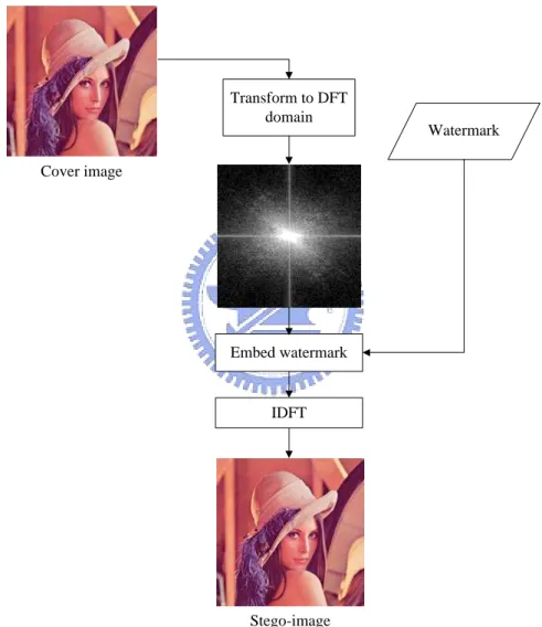
(17) 3. Stego-image: A stego-image is an image that is produced by embedding a watermark into a cover image. 4. Authentication image: An authentication image is an image that is obtained by checking the embedded authentication signals. 5. Embedding process: An embedding process is a process to embed data in an image. 6. Extraction process: An extraction process is a process to extract data from an image. 7. Authentication process: An authentication process is a process to detect whether a stego-image is tampered with or not.. 1.3.2. Brief Descriptions of Proposed Methods. In this study, we focus on dealing with full-color images. And for them, different watermarking methods will be proposed to handle different attacks.. A.. Copyright Protection by Watermarking for Color Images against Rotation and Scaling Attacks Using Coding and Synchronization of Peak Locations in DFT Domain A method for copyright protection by watermarking for color images against. rotation and scaling attacks using coding and synchronization of peak locations in the DFT domain is proposed, in which a watermark is embedded in a color image to create a stego-image. First, a serial number is embedded as a watermark into a cover image by adjusting the magnitude values of the coefficients in the middle band of the DFT domain to create peaks and coding their locations in certain concentric circles in the band as watermark signals. A peak for synchronization is also embedded in the 5.
(18) middle band. The embedded watermark can be extracted from the stego-image by coefficient-value peak detection in the DFT domain. By this method, the embedded watermark becomes robust to survive rotation and scaling attacks. Figure 1.1 shows a flowchart of the proposed embedding method.. Transform to DFT domain. Watermark. Cover image. Embed watermark. IDFT. Stego-image. Figure 1.1 Flowchart of first proposed method of watermarking for copyright protection.. 6.
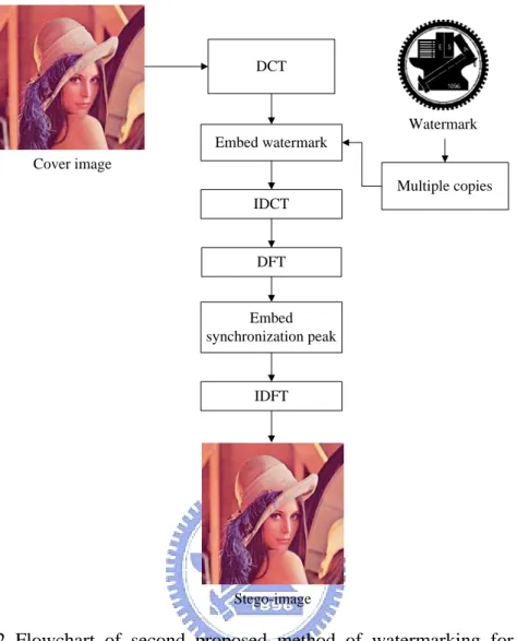
(19) B.. Copyright Protection by Watermarking for Color Images against Rotation And Cropping Attacks Using Synchronization of Peak Locations in DFT Domain And Coefficient Relationship Comparison in DCT Domain A method for copyright protection by watermarking for color images against. rotation and cropping attacks using synchronization of peak locations in the DFT domain and DCT-coefficient relationship comparison is proposed. A synchronization peak is embedded into a cover image in the DFT domain and a binary image as a watermark is multiply duplicated and embedded into the 8×8 blocks of the cover image in the DCT domain by adjusting the magnitude relation of certain selected DCT coefficients. The synchronization peak is detected later to check whether the stego-image has been rotated or not. Finally, the embedded watermark can be extracted from the DCT domain by checking the relationship of the DCT coefficients. Using this method, the embedded watermark becomes resistant to rotation and cropping attacks. Figure 1.2 shows a flowchart of the embedding method.. C.. Copyright Protection by Watermarking for Color Images against Print-and-Scan Operations Using Coding and Synchronization of Peak Locations in DFT Domain A method for copyright protection by watermarking for color images against print. and scan operations using coding and synchronization of peak locations in the DFT domain is proposed. A rescanned image always has pixel-value distortion and geometric transformations, like scaling, slight rotation, and a little zero padding. The pixel-value distortion means that the color and luminance of the image pixels have been altered. 7.
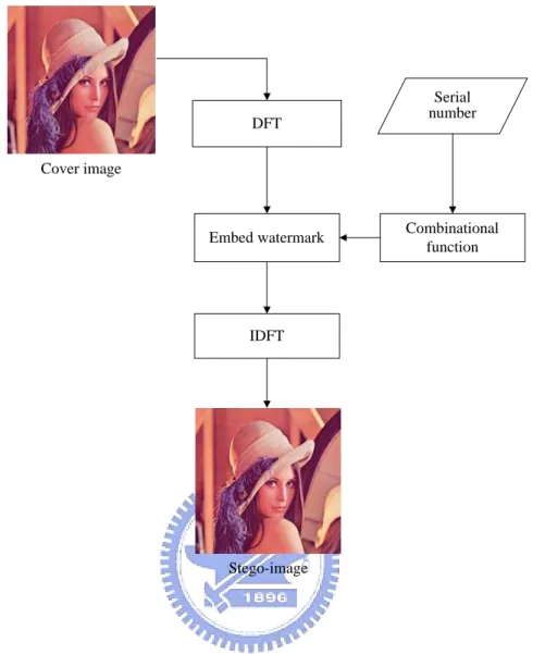
(20) DCT. Watermark. Embed watermark. Cover image Multiple copies. IDCT. DFT. Embed synchronization peak. IDFT. Stego-image. Figure 1.2 Flowchart of second proposed method of watermarking for copyright protection.. Therefore, a watermark embedded in a rescanned image must be provided with robustness against pixel-value distortion and geometric operation attacks. In the proposed method, watermark signals are embedded in certain concentric circles in the DFT domain by adding coefficient-value peaks in the middle band and using a combinatorial function to code the peak locations. In the extraction process, the positions of the coefficient-value peaks are detected and mapped into a combinatorial function to get a watermark signal. In addition, the synchronization peak is detected, too. By the proposed method, the watermark can survive print and scan operations. Figure 1.3 shows a flowchart of the proposed method. 8.
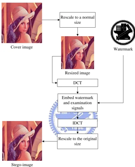
(21) DFT. Serial number. Cover image. Embed watermark. Combinational function. IDFT. Stego-image. Figure 1.3 Flowchart of proposed third method of watermarking against print-and-scan operations.. D.. Copyright Protection by Watermarking for Color Images against Scaling And Line-Removal Attacks Using An Image Rescaling Technique In this topic, we focus on watermarking for color images against scaling and. line-removal attacks. The proposed methods are based on those proposed by Cheng and Tsai [23] and Yin and Tsai [5], which embed invisible watermarks into images in the DCT domain. We improve it by rescaling an image to a pre-determined normal size before the embedding and extraction processes, and inserting certain verification 9.
(22) codes to check whether a watermark is embedded in the extraction processes. Figure 1.4 shows a flowchart of the proposed method for this topic.. Rescale to a normal size. Cover image. Watermark. Resized image. DCT. Embed watermark and examination signals. IDCT. Rescale to the original size. Stego-image. Figure 1.4 Flowchart of fourth proposed method of watermarking against scaling and line removal.. E.. Tampering Detection in Color Images by Signature-Free Authentication Using DCT-Coefficient Relationship Comparison A method for image authentication in color images without the use of signatures 10.
(23) is proposed. Authentication signals, randomly generated by a key and some information of an image, are embedded into each 8×8 image block in the DCT domain by adjusting the magnitude relationship of the coefficients. There is no need to save an extra signature file, which contains image features, when authenticating a suspicious image later. The signature file is a waste of storage space and makes the file management more complicated. By checking the relationships of the selected DCT coefficients of the image block, the fidelity and integrity of the image can be verified. Figure 1.5 shows a flowchart of the proposed method.. 1.4 Thesis Organization In the remainder of this thesis, the proposed method for copyright protection by watermarking for color images against rotation and scaling attacks is described in Chapter 2. In Chapter 3, the proposed method for copyright protection by watermarking for color images against rotation and cropping attacks is described. And in Chapter 4, the proposed method for copyright protection by watermarking for color images against print-and-scan operations is described. In Chapter 5, the proposed method for copyright protection by watermarking for color images against scaling and line-removal attacks using an image rescaling technique is described. In Chapter 6, the proposed method for tampering detection in color images by signature-free authentication via DCT-coefficient relationship comparison is described. Finally, in Chapter 7, we give some conclusions and briefly point out some possible directions for future research works.. 11.
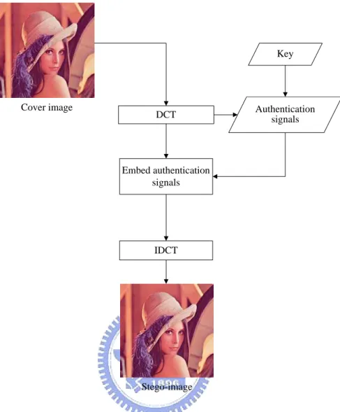
(24) Key. Cover image. DCT. Authentication signals. Embed authentication signals. IDCT. Stego-image. Figure 1.5 Flowchart of proposed method for temper detection.. 12.
(25) Chapter 2 Copyright Protection by Watermarking for Color Images against Rotation and Scaling Attacks Using Peak Detection and Synchronization in DFT Domain The proposed method for copyright protection of color images against rotation and scaling attacks is described in this chapter. The main idea is to embed a watermark as coefficient-value peaks in the DFT domain of an input image. Then, by detecting the peaks in the DFT domain, the embedded watermark can be extracted.. 2.1 Introduction Digital watermarking is a technique for embedding a watermark into an image to protect the owner’s copyright of the image. The embedded watermark must be robust. The stego-image may be rotated or scaled by illicit users. It is desirable that after applying these operations on the stego-image, the watermark is not fully destroyed and can be extracted to verify the copyright of the image. The remainder of this chapter is organized as follows. In Section 2.2, the idea of the proposed method will be described. By certain properties of the DFT coefficients, we can embed a watermark in the DFT domain with robustness against rotation and. 13.
(26) scaling attacks. In Section 2.3, the proposed watermark embedding process is presented. In Section 2.4, the proposed watermark extraction process is described. In Section 2.5, some experimental results are illustrated. Finally, in Section 2.6 some discussions and a summary are given.. 2.2 Idea of Proposed Method 2.2.1. Properties of Coefficients in DFT Domain. After applying a discrete Fourier transformation (DFT) to an input image, the DFT coefficients in the frequency domain can be obtained. The DFT of an image. f ( x, y ) of size M × N can be described by the equation described below: F (u , v) =. 1 MN. M −1 N −1. ∑ ∑ f ( x, y )e x =0. − j 2π ( ux / M + vy / N ). .. (2.1). y =0. The Fourier transform is a complex function of the real frequency variables. It has several properties, and some of them are described in the following. A.. Symmetry property. If a 2D signal is real, then the Fourier transform has a symmetry property, as shown by the following equation [27]: F (u, v) = F ∗ (−u,−v) .. (2.2). The symbol ( ∗ ) indicates complex conjugation. Because the Fourier transform of an image can be complex, we can divide it into two functions. One is the magnitude 1. function or spectrum | F (u , v) |= [ R 2 (u , v) + I 2 (u , v)] 2 , and the other the phase ⎡ I (u , v) ⎤ function φ (u, v) = tan −1 ⎢ ⎥ , where R (u, v) and I (u , v) are the real and ⎣ R(u, v) ⎦ 14.
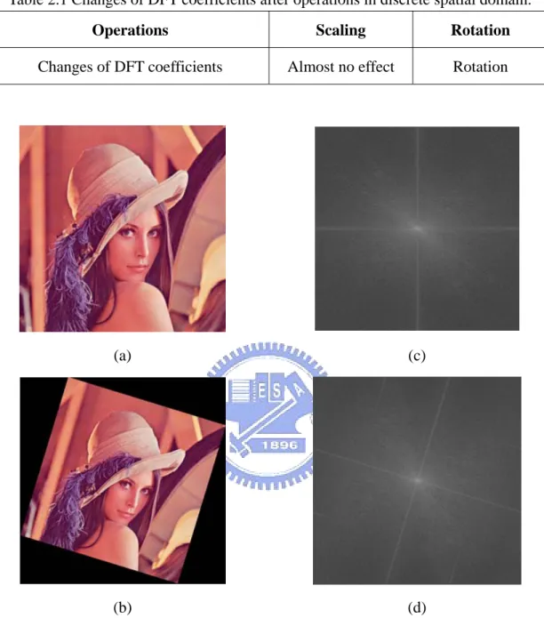
(27) imaginary parts of F (u, v) . And for real signals, Equation (2.2) leads to: | F (u , v) | = | F (−u ,−v) | .. (2.3). It means that the magnitude value of a coefficient (or simply a coefficient value) and its symmetric version are equal. In addition, both the magnitude and the phase functions are necessary for complete reconstruction of an image from its Fourier transform. But the magnitude part is less important than the phase part. The magnitude-only image is unrecognizable. On the contrary, the phase-only image is barely recognizable [24]. Therefore, we may calculate and adjust the magnitude values of the DFT coefficients to embed information without causing significant loss of image quality. B.. Invariant properties of rotation and scaling. After we apply some image processing operations like rotation and scaling to an image, the coordinates and magnitude values of the DFT coefficients of the image will be altered, too. Changes of the DFT coefficients after scaling and rotation operations in the discrete image domain are listed in Table 2.1 [28]. The scaling operation has almost no effect on the DFT coefficients. It means that when an image is scaled, each DFT coefficient is the same as the original one except only with some noise. On the other hand, after rotating an image in the spatial domain, the locations of the DFT coefficient values will have the same rotation in the DFT domain. Figures 2.1(a) and (b) show an original image and a rotated version of it. And the corresponding Fourier spectrum images, in which each pixel value is equal to the magnitude value of the DFT coefficient, are shown in Figures 2.1(c) and (d), respectively. Note that the Fourier spectrum image in Figure 2.1(d) has the same rotation like Figure 2.1(b).. 15.
(28) Table 2.1 Changes of DFT coefficients after operations in discrete spatial domain. Operations. Scaling. Rotation. Changes of DFT coefficients. Almost no effect. Rotation. (a). (c). (b). (d). Figure 2.1 Input images, and Fourier spectrum images of G channel. (a) Image “Lena”. (b) Image “Lena” after rotation. (c) Fourier spectrum image of image “Lena” (d) Fourier spectrum image with the same rotation angle of (b).. 2.2.2. Properties of Color Channels. A full-color image has three color channels, namely, red (R), green (G), and blue (B). Generally speaking, we can embed watermark information into all of these three 16.
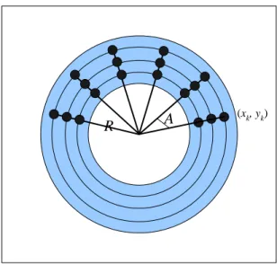
(29) channels. However, human eyes are less sensitive to the frequency of blue color. And its greatest sensitivity is distributed over the region of the yellow/green frequency [25]. In addition, according to experiments, a watermark can be embedded into both red and blue channels in the DFT domain without creating perceivable effects. On the contrary, hiding information in the green channel is too sensitive to human vision. If we embed the watermark in the DFT domain of the green channel, the stego-image will appear to include obvious reticular effects.. 2.2.3. Proposed Technique of Using DFT Peaks for Watermarking. In the proposed watermarking method, after the zero frequency point F(0,0) is shifted to the center of the DFT domain, a watermark is embedded in a ring region which covers a middle band, denoted as B subsequently, in the frequency domain between two circles with two pre-selected radii R1 and R2 where R1 < R2, as shown in Fig. 2.2. The middle band of the frequency domain is divided into n equally-spaced concentric circles with radii r1, r2, …, rn, and into m angle ranges with starting angles. θ1, θ2, …, θm, as seen in Fig. 2.3. Then, n×m embeddable positions p1, p2,…, pn×m are selected in this study to be located at (uk, vk) in the frequency domain described by: pk = (uk, vk) = (ricosθj, risinθj),. (2.4). where 1 ≤ i ≤ n, 1 ≤ j ≤ m and 1 ≤ k ≤ n×m, and at each embeddable position pk, the coefficient value is adjusted to be a local peak in the frequency domain. More specifically, let W be a watermark to be embedded, which is taken to be a serial number in this study in the form of a bit stream, and let M(uk, vk) be the DFT coefficient value at an embeddable position pk = (uk, vk). Then, we embed a watermark 17.
(30) bit wi at pk in the frequency domain in this study by modifying M(uk, vk) to be a local peak M’(uk, vk) by the following equation: M’(uk, vk) = M(uk, vk) + c×wi. (2.5). where c is a pre-selected parameter that determines the strength of the embedded watermark signal. It is noted that, when conducting watermarking in the above way of changing the DFT coefficient value at an embeddable position pk = (uk, vk) for the amount of δ = c×wi, we must preserve the positive symmetry property of the DFT [26] by changing. the corresponding coefficient value at pk’= (−uk, −vk) for the same amount δ. Otherwise, the peak created at pk will be counteracted by the symmetric coefficient value at pk’ after applying the inverse DFT. That is, we must perform, as is done in this study, the following operation M’(−uk, −vk) = M(−uk, −vk) + δ. (2.6). in addition to Eq.(2.5) each time we embed a watermark bit wi at an embeddable position pk = (uk, vk).. R1 R2. Figure 2.2 A ring region of middle frequency band. 18.
(31) A. R. (xk, yk). Figure 2.3 The ring region divided into concentric circles and into angular sectors.. 2.2.4. Proposed Technique for Synchronizing Peak Locations for Protection against Rotation and Scaling Attacks. In order to deal with rotation and scaling attacks, an extra local peak Psync, called synchronization peak, is created in the DFT domain to serve as a signal for synchronizing the peak locations p1, p2, …, pn×m mentioned previously in a way. described later. Psync is embedded into the previously-mentioned middle frequency band B at a location psync described by: psync = (usync, vsync). = (rsynccosθsync, rsyncsinθsync). (2.7). where rsync is selected to be larger than R2 and θsync is a pre-selected angle value. We adjust the DCT value M of Psyn to be a peak value M’ = M + c where c is the constant value mentioned previously. 19.
(32) We now describe how we use the synchronization peak Psync in the proposed watermark extraction process to calculate the rotation angle of a tampered stego-image which suffered possibly from a rotation attack. Because of the DFT properties mentioned previously and illustrated by Fig. 1, if a stego-image is rotated, the location of Psync will also be changed with the same rotation angle. We may calculate first the new angle θ’sync of Psync and take the difference ∆θ between θ’sync and θsync to decide whether the stego-image has been rotated: if ∆θ ≠ 0, then rotated; else, not. If rotated, then we find the angles θ’k of the remaining local peaks, and compute their original angles θ"k by. θ"k = θ’k − ∆θ.. (2.8). On the other hand, as mentioned previously, if a stego-image is rescaled, the DFT coefficient values are almost unaffected. It means that the radii of the local peaks will not be changed.. 2.3 Watermark Embedding Process As mentioned previously, a watermark used for image ownership protection is assumed to be a serial number in this study, and the watermark is transformed into a watermark bit stream. In this section, the process of embedding a watermark bit stream in a color image will be described.. 2.3.1. Embedding of Watermarks. In the proposed watermark embedding process, we use the two channels of red and blue to embed a watermark bit stream in the DFT domain according to the idea described in Section 2.2.2. And the middle band area of the Fourier spectrum is 20.
(33) divided into several concentric circles. Then, the watermark bit stream is embedded in the region of the concentric circles. Furthermore, the watermark bit stream is divided into two halves to be embedded in the red and blue color channels, respectively. For either channel, the spatial domain is transformed into the frequency domain by the DFT. In the middle band of the DFT domain, locations that can be use to create peaks are decided according to the scheme described in Section 2.2.3. Then, we can get pairs of locations (uk, vk) and (−uk, −vk). Using the watermark bit stream W, if a bit wk of W equals “1,” coefficient values of the corresponding embeddable positions (uk, vk) and (−uk, −vk) are adjusted to be peaks by Eqs. (2.5) and (2.6) to embed a watermark bit. On the contrary, if wk equals “0”, the corresponding coefficient values are not changed. In addition, a synchronization peak is also embedded into the middle frequencies according to the scheme described in Section 2.2.4.. 2.3.2. Detailed Algorithm. The inputs to the proposed watermark embedding process are a color image C and a watermark W. The output is a stego-image S. The process can be briefly expressed as an algorithm as follows. Figure 2.4 shows a flowchart of the process. Algorithm 1: Watermark embedding process. Input: A given color image C and a watermark W. Output: A stego-image S. Steps.. 1.. Transform the red and blue channels of C into the frequency domain by the DFT to get C’red and C’blue.. 2.. Divide W into two parts Wred = w1w2…wl and Wblue = wl+1wl+2…w2l. 21.
(34) 3.. Embed Wred and Wblue into C’red and C’blue, respectively, by performing the following operations. 3.1 Decide n radiuses R = {r1, r2,…, rn} of equally-spaced concentric circles in the middle band between two circles with radiuses R1 and R2, with R1< R2.. 3.2 Decide m angles Θ = { θ 1 , θ 2 ,…, θ m } equally distributed in the range from 0° to 180° . Also, take l to be m × n . 3.3 Obtain l positions P = {p1, p2,…, pl} with pk (k = 1, 2, …, l) located at ( ri cos θ j , ri sin θ j ) with k = (i − 1)×m + j, and their l symmetric positions Q = {q1, q2,…, ql} with qk located at the symmetric location of pk , where 1 ≤ i ≤ n , and 1 ≤ j ≤ m . 3.4 If watermark bit wk equals 1, then adjust the pair of the coefficient values located at pk and qk to be local peaks by Eqs. (2.5) and (2.6), where 1 ≤ k ≤ l for C’red or l + 1 ≤ k ≤ 2l for C’blue. 3.5 Add a synchronization peak Psync according to the scheme described in Section 2.2.4. 4.. Transform the C’red and C’blue back into the spacial domain by the inverse DFT.. 5.. Take the final result as the desired stego-image S.. 22.
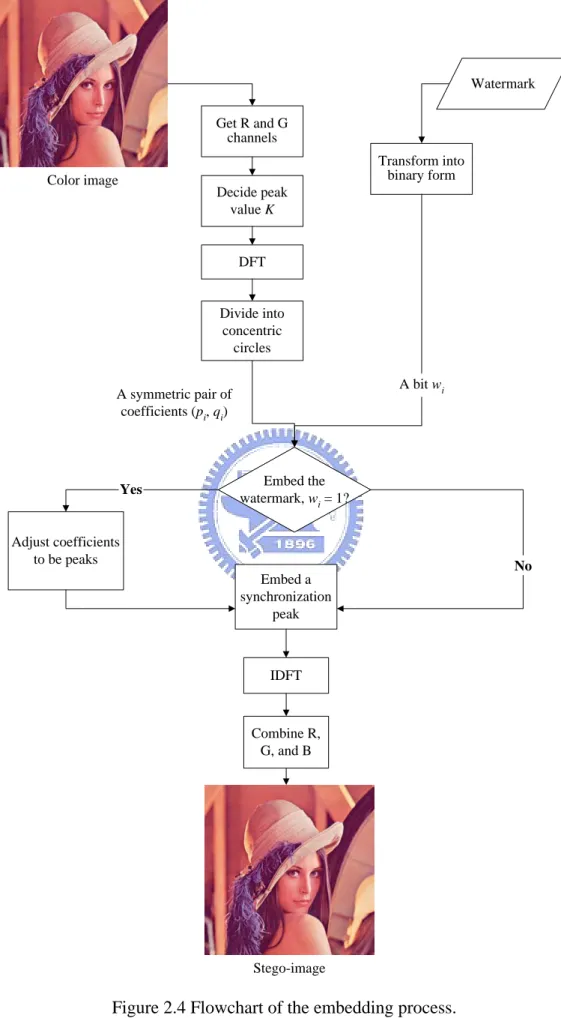
(35) Watermark Get R and G channels Transform into binary form. Color image. Decide peak value K. DFT. Divide into concentric circles A bit wi. A symmetric pair of coefficients (pi, qi). Yes. Embed the watermark, wi = 1?. Adjust coefficients to be peaks. No. Embed a synchronization peak. IDFT. Combine R, G, and B. Stego-image. Figure 2.4 Flowchart of the embedding process. 23.
(36) 2.4 Watermark Extraction Process In the proposed watermark extraction process, no other information but the stego-image is needed as the input. The watermark can be extracted to verify the copyright. The processes of applying this technique will be described in this section. And a detailed algorithm for the process will be given.. 2.4.1. Extraction of Watermarks. In the proposed watermark extraction process, the red and blue channels of a stego-image are accessed. Each of these two channels is transformed into the DFT domain. Then, the local peaks in the middle frequency band of the DFT domain are detected using a pre-selected threshold value T: if any DFT coefficient value M is larger than T, it is judged to be a local peak. Because of the symmetry property of the DFT coefficient values specified in Eq. (2.3), we may only detect peaks within the range of the upper-half Fourier spectrum image. After collecting all the peaks, a detected peak with the largest radius r’sync and angle θ’sync is taken to be the synchronization peak, which is then used to synchronize all the remaining peaks in a way described by Eq. (2.8). The result is a set of local peaks P’ = {p'1, p'2,…, p'h}. Then, we calculate the new radius r’sync of Psync and take the ratio ρ between r’sync and rsync to decide R'1 = R1 × ρ and R'2 = R2 × ρ. Also, we divide the ring area of the middle frequency band B between the two circles with radii R'1 and R'2 into n equally-spaced concentric circles and into m angle ranges to make B become a set of l sectors D = {d1, d2,…, dl} where l = m×n, as seen in Figure 2.5. Then, we compare P’ and D to decide the watermark bit stream W = w1w2…wl by:. 24.
(37) ⎧1 if certain pi ' falls in d k , wk = ⎨ ⎩0 otherwise,. (2.9). where 1 ≤ k ≤ l and 1 ≤ i ≤ h. This means that, if there is a peak within a sector dk, the bit wk is set to be “1;” otherwise, “0.” Finally, we transform the bit stream into an integer number as the extracted watermark and complete the watermark extraction process. The detail of the process can be described as an algorithm as follows.. d4. d3. d2 d d1 6. d5. R’2. R’1. Figure 2.5 The middle frequency band is separated into concentric circles and into angular sectors.. 2.4.2. Detailed Algorithm. The input to the proposed watermark extraction process includes just a stego-image S. The output is a watermark W that is a serial number embedded presumably in S. The extraction algorithm can be expressed as an algorithm as follows. Figure 2.6 illustrates the proposed process of watermark extraction.. 25.
(38) Algorithm 2: Watermark extraction process.. Input: A stego-image S. Output: A watermark W. Steps. 1.. Transform the red and blue color channels of S into the DFT domain to get Fourier spectra S’red and S’blue.. 2.. Detect peaks within the upper halves of S’red and S’blue, respectively, by performing the following operations. 2.1 Use a threshold value T to detect peaks in the middle-frequency band. If a coefficient value is larger than T, it is considered as a peak. 2.2 Select the peak with the largest radius as the synchronization peak Psync, and calculate its angle change ∆θ with respective to the original angle of the synchronization peak. 2.3 Reconstruct the angles of the remaining peaks by Eq. (2.8) to get their new locations P’ = {p'1, p'2,…, p'h}. 2.4 Divide the middle frequency band between R'1 and R'2 into n equally-spaced concentric circles and into m sectors to make B become a set of l sectors D = {d1, d2, …, dl}, where l = m×n. 2.5 Compare P’ and D to decide the watermark bit stream according to the way specified by Eq. (2.9).. 3.. Concatenate the two watermark bit streams obtained from processing S’red and S’blue sequentially, and transform the result into a serial number as the desired watermark W.. 26.
(39) Stego-image. Get R and G channels. Decide a threshold value T. DFT. Detect peaks. Find synchronization peak. Reconstruct angles of remaining peaks. Decode watermark bit stream. Watermark. Figure 2.6 Flowchart of the extraction process. 27.
(40) 2.5 Experimental Results Some experimental results of applying the proposed method are shown here. A serial number 877 is transformed into binary form to be a watermark bit stream. The factor c that determines the embedded watermark strength is assigned to be 1.5. Figure 2.7 shows an input image with size 512×512. And Figure 2.8(a) shows the stego-image of Figure 2.7 after embedding the watermark. In addition, Figures 2.8(b) and (c) show the corresponding Fourier spectrum image and the detected locations of the peaks marked with red and green marks. The green mark is the synchronization peak. Figure 2.8(d) show a rotated image of Figure 2.8(a) and the corresponding Fourier spectrum image and the detected peak locations are shown in Figures 2.8(e) and (f), respectively. It shows that the Fourier spectrum image have the same angle of rotation with the tampered image. Figure 2.9(a) shows a scaled image of Figure 2.8(a) and the corresponding Fourier spectrum image with the detected peak locations are shown in Figure 2.9(b). The embedded peaks can be successfully detected in our experiments. Figures 2.10(a) and (b) show two other color images both with size 512×512. And the corresponding stego-images after embedding the watermark are shown in Figures 2.10(c) and (d), respectively. The corresponding PSNR values are shown in Table 2.1, which show that the quality of each of the stego-images is still good. And the embedded watermark is imperceptible by human vision. Finally, two rotated images are shown in Figures 2.11(a) and (b). And Figures 2.12(a) and (b) show two scaled images. The watermarks can be extracted successfully from each of these images by the proposed watermark extraction process in our experiments.. 28.
(41) Figure 2.7 An input image “Lena”.. (a). (d). (b). (e). Figure 2.8 An output stego-images with the watermark, the tampered image and Fourier spectrum images. (a) Stego-Image “Lena”. (b) Fourier spectrum image of (a). (c) Peak locations of (c). (d) Tampered image after rotating 13 degree clockwise. (e) Fourier spectrum image of (d). (f) Peak locations of (e). 29.
(42) (c). (f). Figure 2.8 An output stego-images with the watermark, the tampered image and Fourier spectrum images. (a) Stego-Image “Lena”. (b) Fourier spectrum image of (a). (c) Peak locations of (c). (d) Tampered image after rotating 13 degree clockwise. (e) Fourier spectrum image of (d). (f) Peak locations of (e) (continued).. (a). (b). Figure 2.9 The tampered image and the Fourier spectrum image. (a) Tampered image after scaling to 90%. (b) Fourier spectrum image of (a) with peak locations.. 30.
(43) (a). (c). (b). (d). Figure 2.10 Input images, and output stego-images with the watermark. (a) Image “Pepper”. (b) Image “Jet”. (c) and (d) Stego-images after embedding the watermark, respectively.. Table 2.2 The PSNR values of recovered images after embedding watermarks.. PSNR. Lena. Pepper. Jet. 33.0. 33.0. 33.0. 31.
(44) (a). (b). Figure 2.11 Some tampered images with different rotations. (a) Tampered image after rotating 97 degree clockwise. (b) Tampered image after rotating 7 degree counterclockwise.. (a). (b). Figure 2.12 Some tampered images with different scaling ratios. (a) Tampered image after scaling to 150%. (b) Tampered image after scaling to 90%.. 2.6 Discussions and Summary In this chapter, we have proposed a method for embedding a watermark into a color image by using peak detection and synchronization of coefficient-value peak locations in the DFT domain. Utilizing some properties of image coefficients in the 32.
(45) DFT domain, we can embed a watermark in the form of a binary stream by creating the peaks circularly and symmetrically in a middle frequency band in the transform domain. On the other hand, an extra synchronization peak is added to synchronize the peak locations. The embedded watermark was shown by the experimental results to be robust against rotation and scaling attacks, thus achieving the goal of image copyright protection. However, the data hiding capability of the proposed watermark embedding method is not large and cannot accommodate a normal-sized logo image. It may be tried to solve this problem in the future.. 33.
(46) Chapter 3 Copyright Protection by Watermarking for Color Images against Rotation And Cropping Attacks Using Synchronization of Peak Locations in DFT Domain And DCT-Coefficient Relationship Comparison In this chapter, the proposed method for embedding a watermark in color images against rotation and cropping attacks is described. The idea is based on hiding information in two frequency domains, the DFT and DCT domains. In the DFT domain, a synchronization peak is embedded for the purpose of detecting if an image is suffered rotation attacks And in the DCT domain, multiple copies of watermarks and verification codes are embedded for the purpose of surviving cropping attacks. The remainder of this chapter is organized as follows. In Section 3.1, an introduction is given first. In Section 3.2, several ideas behind the proposed methods are described. In Section 3.3, the proposed watermark embedding process is presented. In Section 3.4, the proposed watermark extraction process is presented. Some experimental results are shown in Section 3.5. And finally, in Section 3.6 some discussions and a summary are made.. 34.
(47) 3.1 Introduction The watermarking technique has been proposed for copyright protection of digital images. However, a watermarked image may suffer many kinds of attacks and image processing operations. In order to achieve the goal of image copyright protection, the watermark must be robust against these attacks. In this chapter, we focus on embedding a watermark to survive rotation and cropping attacks.. 3.1.1 Problem Definition In order to embed watermarks in color images for surviving rotation and cropping attacks, invariant features of images with respect to rotation and cropping operations should be adopted. After a cropping attack, a tampered image becomes just part of an original image, in which many pixel values are lost, as we can see in the example shown in Figure 3.1. In this case, the embedded watermark may be destroyed or lose too much information to complete the watermark extraction work. After a rotation attack, a stego-image is rotated for a certain angle. In the subsequent watermark extraction process, the location in the frequency domain where the watermark can be extracted may be shifted. We call this situation a watermark synchronization problem. The proposed method has the merit of integrating techniques applied in the two frequency domains to achieve resistance capabilities to rotation and cropping attacks. Another merit is that the watermark can be extracted without referencing the original image.. 35.
(48) (a). (b). Figure 3.1 A color image and a cropped image. (a) Color image “Lena”. (b) Cropped image of (a).. 3.1.2. Review of Employed Techniques. In Yin and Tsai [5], annotation data, which are duplicated for many times before embedding, are embedded in the DCT domain by changing the magnitude relation of two DCT coefficients denoted as S1 and S2 and located at (1,4) and (2,3) in the standard quantization table within every 8×8 image blocks. And a voting process will be proceeded in the extraction process to decide the final extracted annotation data. In Cheng and Tsai [23], an invisible watermark, which can survive JPEG compression, were proposed. A bit of the watermark was embedded into an 8×8 image block by adjusting the magnitude relation of the two DCT coefficients at (1,4) and (2,3) in the standard quantization table. By the magnitude relation of two DCT coefficients, the embedded invisible watermark can be extracted. Table 3.1 shows the standard quantization table. And the methods of adjusting the magnitude relation of 36.
(49) two selected DCT coefficients S1 and S2 are described as follows: ⎧if b = 1 and S1 < S 2 , then Swap (S1 , S 2 ), ⎨ ⎩if b = 0 and S1 ≥ S 2 , then Swap (S1 , S 2 ).. (3.1). The way of changing the magnitude relation of two DCT coefficients includes four situations as follows. 1.. If a bit b of the embedding data is “1” and the relationship of a pair of AC coefficients S1 and S2 is S1≧S2, then S1 and S2 are unchanged.. 2.. If b is “1” and S1≦S2, then S1 and S2 are exchanged.. 3.. If b is “0” and S1≧S2, then S1 and S2 are exchanged.. 4.. If b is “0” and S1≦S2, then S1 and S2 are unchanged.. That is, if the bit to be embedded is “1”, the relation S1 ≥ S2 is created; otherwise, S1 < S2 created. Later, by checking the magnitude relation of the two selected DCT coefficients within every 8×8 image block as follows, a hidden bit e can be reconstructed: ⎧1 if S1 ≥ S 2 , e=⎨ ⎩0 if S1 < S 2 .. (3.2). That is, if S1 ≥ S2, the embedded bit is taken to be “1;” otherwise, “0”.. 3.2 Ideas of Proposed Method The ideas involved in the proposed embedding process are described as follows.. 37.
(50) Table 3.1 A standard quantization table in the JPEG compression standard (luminance component). (u,v) 0. 3.2.1. 1. 2. 3. 4. 5. 6. 7. 0. 16 11 10 16 24 40 51 61. 1. 12 12 14 19 26 58 60 55. 2. 14 13 16 24 40 57 69 56. 3. 14 17 22 29 51 87 80 62. 4. 18 22 37 56 68 109 103 77. 5. 24 35 55 64 81 104 113 92. 6. 49 64 78 87 103 121 120 101. 7. 72 92 95 98 112 100 103 99. Proposed Technique for Multiply Embedding Watermark in DCT Domain for Preventing Cropping Attack. A watermark used for image ownership protection is assumed to be a binary image in this study, called a watermark image. First, the watermark image is rescaled to a pre-determined size n×m. In the proposed method, a secret key and a random number generator are employed to randomize the locations of pixels of the rescaled watermark image to get a randomized watermark image Wr. In addition, Wr is multiply duplicated to get a large randomized watermark image Wl. Let C be the cover image of size M×N. Because we only embed a bit of Wl in an 8×8 image block, the. ⎢ M ⎥ ⎢ N ⎥ number d of copies of Wr is ⎢ × , where ⎣•⎦ means the integer floor ⎣ 8 × m ⎥⎦ ⎢⎣ 8 × n ⎥⎦ function. Then, Wl is embedded into a cover image by changing the magnitude relation of two DCT coefficients within every 8×8 image blocks in the DCT domain.. 38.
(51) The embedding process is based on the method described in Section 3.1.2.. 3.2.2 Proposed Technique for Hiding Verification Code in DCT Domain for Watermark Existence Check When a stego-image is suffered from cropping attacks, the synchronization of the 8×8 image blocks is missed. This means that the locations of the 8×8 image blocks are not the same as the original ones. In order to synchronize the 8×8 image blocks to ensure success of watermark extraction, we try to extract verification codes to make sure that the locations of image blocks are the same as the original ones. In the proposed method, the verification code is a pre-defined square pattern with the same size n×m as the randomized watermark image. The square pattern is shown in Figure 3.2 with a quarter of its pixels being white and three-fourths black. Then, we select two DCT coefficients at (S3, S4) and embed multiple copies of the verification patterns by Eq. (3.1) described previously. In the watermark extraction process, we set a start location and get a sub-image of the stego-image with the range of embedding a square pattern. Then, we extract each bit from 8×8 image blocks of the sub-image by Eq (3.2) and search in it one copy of the verification pattern. If we cannot extract the verification pattern, the start location is shifted a pixel in zigzag order to extract again. If one copy of the verification patterns can be extracted successfully, the locations of the 8×8 image blocks can be synchronized. This means that the watermark can be extracted from the sub-image in sequence.. 39.
(52) Figure 3.2 A square verification pattern.. 3.2.3. Proposed Technique for Hiding Synchronization Peak in DFT Domain to Detect Rotated Angle. In order to synchronize the 8×8 image blocks in a rotated stego-image, we should know the angle of rotation, and rotate the stego-image reversely. Then, we use the verification codes to check the location where the watermark can be extracted. As we described the properties of the DFT coefficients in Section 2.2.1, a synchronization peak can be embedded into the DFT domain of a cover image in the way described in Section 2.2.4. By detecting the change of the synchronization peak location, we can check whether the stego-image has been rotated or not. If the stego-image is rotated, the rotation degrees will be the same as the angle changes of the synchronization peak. Then, we can detect the angle of rotation and rotate the stego-image reversely. In this situation, there may be an opportunity for the stego-image to synchronize the locations of the image blocks with the original ones, and the watermark can be extracted from the image blocks.. 3.3 Proposed Watermark Embedding Process 40.
(53) In this section, the method proposed to embed watermarks in color images and to extract the watermark from stego-images is described. In order to embed a watermark to survive rotation and cropping attacks, two frequency domains, DFT and DCT domains, are adopted in this study. And the watermark is assumed to be a binary image. The watermark embedding process is presented subsequently.. 3.3.1. Embedding of Watermarks. In the proposed embedding watermark process, a watermark W is resized to m×n and the locations of the pixels are randomized with a key K and a random generator G to get a randomized watermark Wr. In addition, let C be the cover image of size M×N. Then, Wr is duplicated into d copies to form a large-sized randomized watermark Wl, ⎢ M ⎥ ⎢ N ⎥ with d = ⎢ × . On the other hand, a verification code E is created ⎣ 8 × m ⎥⎦ ⎢⎣ 8 × n ⎥⎦ according to a pre-defined pattern image with the size of M×N. And E is also duplicated into d copies to form a multiple-copies pattern image El. Based on the employed method described in Section 3.1.2, C is divided into non-overlapping 8×8 image blocks. For each image block, the RGB color values of the block are transformed into the YCbCr color values. The 8×8 FDCT is performed on the Y channel of the resulting image. Two pairs of DCT coefficients (S1, S2) and (S3, S4), each coefficient pair having the same quantization step size within the JPEG standard quantization table, are selected. Then, we adjust the first pair of DCT coefficients to embed an image pixel of Wl and the second pair to embed a pixel of El by Eq. (3.1). The 8×8 inverse DCT are then performed on these DCT coefficients and then the YCbCr color values are transformed back into RGB color values. After all blocks are processed, we transform the image into the DFT domain. And a synchronization peak is embedded according to the method described in Section 3.2.3. Finally, we use the 41.
(54) inverse DFT to transform the DFT-domain image into the spatial domain. A stego-image is thus obtained. A detailed algorithm for the watermark embedding process is described next.. 3.3.2. Detailed Algorithm. The inputs to the proposed watermark embedding process include a color image C, a watermark W, a square verification pattern E, a secret key K, and a random generator G. The output is a stego-image S. The process can be briefly expressed as an algorithm as follows. Figure 3.3 shows a flowchart of the embedding process. Algorithm 1: Watermark embedding process.. Input: A given color image C, a watermark W, a verification pattern E, a secret key K, and a random generator G. Output: A stego-image S. Steps. 1.. Divide C of size M×N into non-overlapping 8×8 image blocks. Let cij be an ⎢M ⎥ ⎢N ⎥ image block of C, where 0 ≤ i ≤ ⎢ ⎥ , and 0 ≤ j ≤ ⎢ ⎥ . ⎣8⎦ ⎣8⎦. 2.. Resize W to a pre-selected size n×m and use K and G to randomize the locations of pixels of resized W to get a randomized watermark image Wr.. 3.. ⎢ M ⎥ ⎢ N ⎥ times, respectively, to × Duplicate E of size n×m and Wr ⎢ ⎣ 8 × m ⎥⎦ ⎢⎣ 8 × n ⎥⎦ form Wl and El. Let wij and eij be the pixel value of Wl and El at position (i, ⎢M ⎥ ⎢N ⎥ j), where 0 ≤ i ≤ ⎢ ⎥ , and 0 ≤ j ≤ ⎢ ⎥ . ⎣8⎦ ⎣8⎦. 4.. Transform every image block into the YCbCr color model.. 5.. Transform the Y channel of each image block into the frequency domain by performing the 8×8 FDCT. 42.
(55) 6.. For each block, two pairs of the DCT coefficients (S1, S2) and (S3, S4) are selected to embed Wl and El. For each pixel wij and the corresponding image block cij, adjust the magnitude relation of the first pair of the coefficients by Eq. (3.1). For each pixel eij and the corresponding image block cij, adjust the magnitude relation of the second pair of the coefficients by Eq. (3.1).. 7.. Transform each image block back into the spatial domain by performing the 8×8 inverse DCT.. 8.. Transform each image block from the YCbCr color model into the RGB color model to get an image H.. 9.. Transform the blue color channel of H into the DFT domain to get a Fourier spectrum F.. 10. Add a synchronization peak Psyn into F according to the scheme described in Section 2.2.4. 11. Transform F back into the spacial domain by the inverse DFT. 12. Take the final result as the desired stego-image S.. 3.4 Watermark Extraction Process In the proposed watermark extraction process, a watermark can be extracted to verify the copyright. The process of applying this technique will be described in this section. And a detailed algorithm for the process will be given.. 3.4.1. Extraction of Watermarks. In the proposed watermark extraction process, the blue color channel of a stego-image is first accessed to extract the synchronization peak to check whether the. 43.
(56) Divide into 8x8 nonoverlapping blocks. Transform to YCbCr color model Cover image. Transform Y channel to DCT domain. Key. Embed watermark and examination signals. Randomize watermark. IDCT. Watermark Transform back to RGB color model. Multiply duplicate. Transform G channel to DFT domain. Image pattern. Embed synchronization peak. IDFT. Stego-image. Figure 3.3 Flowchart of the proposed embedding process. 44.
(57) stego-image is rotated or not. By the way described in Section 3.2.3, we can know the angle of rotation from the change of synchronization peak location and rotate the stego-image reversely to get Sr. In addition, Sr is divided into non-overlapping image blocks, and the magnitude relation of a pair of coefficients at (S3, S4) in each image block of the range of a square pattern is checked to extract the verification code. If the extracted data do not equal the verification code, we shift the locations of image blocks in a zigzag order to check again. As long as the extracted data equal the verification code, we can extract watermark pixels from each image block of the same locations by comparing the magnitude relation of the DCT coefficients at (S1, S2). Finally, we use a key and a random generator to recover the locations of the watermark image pixels. Then we can get the extracted watermark. This completes the extraction process of the watermark.. 3.4.2. Detailed Algorithm. The input to the proposed watermark extraction process includes a stego-image S, a secret key K, and a random generator G. The output is a watermark W that is a binary image embedded presumably in S. The extraction algorithm can be expressed as an algorithm as follows. Figure 3.4 illustrates the proposed process of watermark extraction. Algorithm 2: Watermark extraction process.. Input: A stego-image S, a secret key K, and a random generator G. Output: A watermark W. Steps. 1.. Transform the blue color channel of S into the DFT domain to get a Fourier spectrum S’blue. 45.
數據
+7


相關文件
In this paper, we propose a practical numerical method based on the LSM and the truncated SVD to reconstruct the support of the inhomogeneity in the acoustic equation with
The hashCode method for a given class can be used to test for object equality and object inequality for that class. The hashCode method is used by the java.util.SortedSet
In this paper, we build a new class of neural networks based on the smoothing method for NCP introduced by Haddou and Maheux [18] using some family F of smoothing functions.
Chen, The semismooth-related properties of a merit function and a descent method for the nonlinear complementarity problem, Journal of Global Optimization, vol.. Soares, A new
The Hilbert space of an orbifold field theory [6] is decomposed into twisted sectors H g , that are labelled by the conjugacy classes [g] of the orbifold group, in our case
學校需確保計算器讀數只包括特許協議所涵蓋的版權印刷作品
To improve the quality of reconstructed full-color images from color filter array (CFA) images, the ECDB algorithm first analyzes the neighboring samples around a green missing
A digital color image which contains guide-tile and non-guide-tile areas is used as the input of the proposed system.. In RGB model, color images are very sensitive
