IEEE ANTENNAS AND WIRELESS PROPAGATION LETTERS, VOL. 8, 2009 189
A Novel Modified Multiband Planar
Inverted-F Antenna
Ya-Chung Yu and Jenn-Hwan Tarng, Senior Member, IEEE
Abstract—A novel multiband modified planar inverted-F an-tenna (PIFA) with a compact single feed is proposed, which covers GSM900 (880–960 MHz), DCS (1710–1880 MHz), PCS (1850–1990 MHz), UMTS (1920–2170 MHz), Bluetooth/WLAN (2400–2480 MHz), WiMAX (2500–2690 MHz), HiperLAN/2 (5470–5725 MHz), and an additional band (4600–4800 MHz). In conventional PIFA, most of time the shorted pin acts as a capacitor load only for impedance matching purpose, which may yield a large ground plane, narrow bandwidth, and large antenna volume due to a long shorted pin to provide enough capacitance. In our design, the shorted pin just acts a short-circuited load, which is an effective way to control the current resonant paths and is a novel way in design a multiband PIFA. Furthermore, with this design and parasitic folded structures, the proposed multiband antenna can be modeled by parallel short-circuited transmission line impedance transformers (TLIT), which can easily create six mentioned frequency bands (from PCS band to HiperLAN/2 band) by adjusting the lengths of folded branches. Measurement result conforms that our multiband design not only provides size reduction of both the antenna and the ground plane but also enhances the bandwidth of the six bands.
Index Terms—Multiband planar inverted-F antenna (PIFA), transmission line impedance transformer, shorted-circuit load.
I. INTRODUCTION
W
ITH rapid development of wireless communications, multiband handsets or customer premise equipments (CPEs) are needed due to the era of digital convergence. There-fore, the RF front-end of transceiver/receiver needs a multiband or broadband and small size antenna to transmit/receive signals of different systems, included GSM900, DCS-1800, PCS-1900, UMTS, Bluetooth/WLAN, and WiMAX. One of the main chal-lenges in designing a multiband antenna is how to create mul-tiresonating paths in a small antenna. In recent years, the planar inverted-F antenna (PIFA) is widely used in mobile device be-cause that it can offer compact size and multiband internal an-tenna operation. Researchers from [1]–[7] proposed to add par-asitic elements a PIFA to radiate more frequency bands. These elements have the same feed but each with individual shorted pin or plate which connects to the ground, and they form aManuscript received March 31, 2008; revised April 27, 2008. First published May 20, 2008; current version published April 22, 2009. This work was sup-ported in part by National Science Council of Taiwan under Contract NSC 96-2752-E-009-014-PAE and Contract NSC 96-2752-E-002-009-PAE.
The authors are with the Department of Communication Engineering, Na-tional Chiao Tung University, Hsinchu 300, Taiwan (e-mail: ntupig@hotmail. com).
Color versions of one or more of the figures in this letter are available online at http://ieeexplore.ieee.org.
Digital Object Identifier 10.1109/LAWP.2008.2000791
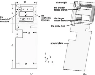
Fig. 1. (a) Front view of the antenna (millimeters) and the dotted-line portion represents the structure behind the antenna surface. (b) 3-D view of the antenna.
Fig. 2. Measured and computed return loss.
multi-PIFA structure. In [8]–[10], some slots are embedded in the main radiating element to create many multiresonating paths and many frequency bands as well. These techniques may need to increase the antenna size in order to create more bands.
In this letter, a novel multiband antenna modified from a PIFA is proposed. In our design, the shorted pin is far away from the feed point and acts only as a short-circuited load, leading to a smaller antenna thickness to compare with the traditional one that the shorted pin is near to the feed to act as a capacitive load. On the other hand, with this design and par-asitic folded branches, the proposed multiband antenna can be modeled by parallel transmission line impedance transformers (TLIT), which helps us to easily achieve the required frequency bands. Additionally, the antenna radiates different frequency
190 IEEE ANTENNAS AND WIRELESS PROPAGATION LETTERS, VOL. 8, 2009
Fig. 3. (a) Current flow distribution of WiMAX band at 2600 MHz. (b) Current flow distribution of HiperLAN/2 at 5600 MHz. (c) Equivalent circuit model of the proposed antenna. The circuit to cover from PCS band to HiperLAN/2 is modeled by 6 parallel transmission lines of different lengths. Beta is the characteristic impedance of the transmission line. The GSM 900 or DCS 1800 band is simply described by a radiating resistance since they both have a monopole structure.
band with the portion of or entire antenna structure, therefore the radiating element can be reused and the antenna size can be reduced effectively.
II. MULTIBANDANTENNADESIGN ANDRESULT
The front view and the 3-D view of the proposed antenna are shown in Fig. 1(a) and (b), respectively. The front view shows that the antenna is composed by an inverted-F structure and an inverted-E structure. The radius and length of the shorted pin shown in Fig. 1(b) are 0.8 and 4 mm, respectively, which is far away from the feed. Two folded branches behind the inverted-F structure with proper dimensions as shown in Fig. 1(b) and the shorted pin positioned far away from the feed create the re-quired resonating paths of the six higher bands, which is val-idated by the simulation result of frequency response shown in Fig. 2. Fig. 2 shows the comparison of the computed and mea-sured return losses. It is found that the meamea-sured frequency re-sponse (less than 10 dB) and impedance matching are better than the simulation ones, especially in the UMTS band. It is noted that the lowest frequency bands, GSM 900 MHz and DCS 1800 MHz are created by the inverted-E structure with a fold patch behind.
Compared with traditional multiband PIFAs [1]–[7], the proposed modified PIFA covers more bands with a smaller size 30 mm 20 mm 4 mm and a smaller ground plane size 30 mm 43 mm. Additionally, our structure is simple and is easy to fabricate. To optimize the return loss over the covered spectrum, the probe feed is located at the join of the inverted-F and E structures. It is noted that when the shorted pin is far away from feed, the inverted-F with the folded structure can be modeled a short-circuited form TLIT, which yields an advantage of easy-to-tune in creating required frequency bands (six bands: from PCS band to HiperLAN/2 band).
The simulations of the current flow distribution of WMAX and HiperLAN/2 bands are shown in Fig. 3(a) and (b), respec-tively. From Fig. 3(a), the current flows through the longer
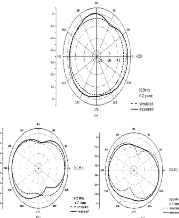
Fig. 4. Measured and simulated radiation patterns of GSM band: (a)x–z plane; (b)y–z plane; and (c) x–y plane.
folded branch, then is blocked at the edge of the shorter folded branch of the inverted-F structure, and finally, returns to the ground plane through the shorted pin. The equivalent circuit model of the current flow-path is described by a short-circuited TLIT of a half-wavelength length, which corresponds to the center frequency of the WiMAX band. Fig. 3(b) shows that the current is blocked by the longer folded branch of the inverted-F
YU AND TARNG: NOVEL MODIFIED MULTIBAND PLANAR INVERTED-F ANTENNA 191
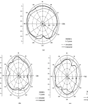
Fig. 5. Measured and simulated radiation patterns of WiMAX band: (a)x–z plane; (b)y–z plane; and (c) x–y plane.
structure and moves to the shorter folded branch and then re-turns to the ground plane through the shorted pin. Similarly, the equivalent circuit model of the current flow-path is described by a short-circuited TLIT of a half-wavelength length, which corresponds to the center frequency of the HiperLAN/2 band. From the simulation result as shown in Fig. 3, it is observed that flow current are accumulated at the folded edge to pro-duce a high potential zone and an inversed electrical field, which changes the current direction. The current flow paths of WiMAX and HiperLAN/2 are path no. 1 and path no. 2 shown in Fig. 3(a) and (b), respectively.
An equivalent circuit model has been shown in Fig. 3(c). The circuit to cover from PCS band to HiperLAN/2 is modeled by 6 parallel transmission lines of different lengths. Each resonant path is modeled by a parallel transmission line of a half wave-length. It is because that the coupling effects among these six frequency components are minimized due to the parasitic folded structures forming as one radiator. It is noted that the GSM 900 or DCS 1800 band is simply described by a radiating re-sistance since they both have a monopole structure. In Fig. 3(c), a slight coupling between inverted-E and inverted-F structures is observed. In the figure, is the short-circuited load of nth transmission line due to the shorted pin, and is the radiation impedance in each band. The is the radiating resistance of the GSM900 or DCS1800 band.
For brevity, Figs. 4–6 only show the measured and simulated radiation patterns (total power gain) at the center frequency of GSM, WiMAX, and HiperLAN/2 bands, respectively. It is found that all the simulation results agree with the measured ones. The omni-directional radiation patterns of the GSM, WiMAX, and HiperLAN/2 bands are found at – plane, –
Fig. 6. Measured and simulated radiation patterns of HiperLAN/2 band: (a) x–z plane; (b) y–z plane; and (c) x–y plane.
plane, and – plane, respectively. The peak gains of the GSM, WiMAX, and HiperLAN/2 bands are 1.9, 4.3, and 3.3 dBi, respectively.
III. CONCLUSION
In this letter, a novel modified PIFA for multiband appli-cations is proposed for covering GSM900 (880–960 MHz), DCS (1710–1880 MHz), PCS (1850–1990 MHz), UMTS (1920–2170 MHz), Bluetooth/WLAN (2400–2480 MHz), WiMAX (2500–2690 MHz), HiperLAN/2 (5470–5725 MHz), and an additional band (4600–4800 MHz). The shorted pin just acts a short-circuited load, which is an effective way to control the current resonant paths. With the shorted pin and only two parasitic folded branches, needed resonant paths are created easily to fulfill multiband requirement. With our approach, antenna analysis is simplified since the circuit is modeled by using the TLIT method to yield the analytical result of the antenna input impedance. This method is much simpler to com-pare with the conventional vector fitting method, which helps us to determine antenna dimension easily. Since the inverted-F structure is shared as a common component for all resonant paths, our design can also reduce the antenna size effectively. Compared the simulation with the measurement, the return loss and radiation pattern are in agreement. In addition, the multiband antenna is small with good radiation patterns.
REFERENCES
[1] B. S. Izquierdo, J. C. Batchelor, R. J. Langley, and M. I. Sobhy, “Single and double layer planar multiband PIFAs,” IEEE Trans. Antennas
Propag., vol. 54, no. 5, pp. 1416–1422, May 2006.
[2] Y. J. Cho, S. H. Hwang, and S.-O. Park, “A dual-band internal antenna with a parasitic patch for mobile handsets and the consideration of the handset case and battery,” IEEE Antennas Wirel.Propag. Lett., vol. 4, pp. 429–432, Apr. 2005.
192 IEEE ANTENNAS AND WIRELESS PROPAGATION LETTERS, VOL. 8, 2009
[3] Y.-X. Guo, M. Y. W. Chia, and Z. N. Chen, “Miniature built-in quad band antennas for mobile handsets,” IEEE Antennas Wirel. Propag.
Lett., vol. 2, pp. 30–32, Feb. 2003.
[4] N. C. Karmakar, P. Hendro, and L. S. Firmansyah, “Shorting strap tun-able single feed dual-band PIFA,” IEEE Microw. Wirel. Compon. Lett., vol. 13, no. 1, pp. 13–15, Jan. 2003.
[5] P. C. , R. S. , G. K. , and C. L. , “Design of an quad-band antenna for mobile phones,” IEEE Microw. Wirel. Compon. Lett., vol. 14, no. 4, pp. 146–150, Apr. 2004.
[6] M. K. Karkkainen, “Meander multiband PIFA with coplanar parasitic patches,” IEEE Microw. Wirel. Compon. Lett., vol. 15, no. 10, pp. 630–632, Oct. 2005.
[7] D. M. Nashaat, H. A. Elsadek, and H. Ghali, “Siggle feed compact quad-band PIFA antenna for wireless communication applications,”
IEEE Trans. Antennas Propag., vol. 53, no. 8, pp. 2631–2635, Aug.
2005.
[8] C. W. Chiu and F. L. Lin, “Compact dual-band PIFA with multi-res-onators,” IEE Electron. Lett., vol. 38, no. 12, pp. 538–540, Dec. 2002. [9] D. Viratelle and R. J. Langley, “Dual-band printed antenna for mo-bile telephone applications,” Proc. Inst. Elect. Eng. Microw. Antennas