國
立
交
通
大
學
資訊科學與工程研究所
碩
士
論
文
一個同儕網路上基於會議初始協定的語音會議系統
A SIP-based audio conferencing system on P2P network
研 究 生:呂學增
指導教授:陳耀宗 教授
一個同儕網路上基於會議初始協定的語音會議系統
A SIP-based audio conferencing system on P2P network
研 究 生:呂學增 Student:Shiue-Tzeng Lu
指導教授:陳耀宗 Advisor:Yaw-Chung Chen
國 立 交 通 大 學
資 訊 科 學 與 工 程 研 究 所
碩 士 論 文
A ThesisSubmitted to Institute of Computer Science and Engineering College of Computer Science
National Chiao Tung University in partial Fulfillment of the Requirements
for the Degree of Master
in
Computer Science July 2008
A SIP-based audio conferencing system on P2P network
Student:Shiue-Tzeng Lu
Advisor:Yaw-Chung Chen
A Thesis
Submitted to Institute of Computer Science and Engineering College of Computer Science
National Chiao Tung University in partial Fulfillment of the Requirements
for the Degree of Master
in
Computer Science July 2008
一個在同儕網路上基於會議初始協定的語音會議系統
學生:呂學增
指導教授:陳耀宗 博士
國立交通大學資訊工程與科學研究所
摘 要
隨著網際網路的頻寬不斷地擴展增加,一些要求較高網路頻宽的服務愈來愈 被廣泛使用,像是網路電話或視訊服務。而在最近十年內,發展了另一種熱門的 網路服務架構:同儕式網路(Peer-to-Peer Network),簡稱為 P2P 網路。在本論文 中,我們試圖結合此一網路架構到我們所提出的語音會議系統。 網路電話目前是網際網路上的一種殺手級應用,並且有許多人正享受著它的 便利與低廉。以目前網路頻寬而言,一對一網路電話的雙向連線可以達到優良的 服務品質(Quality of Service,QoS),然而在更進一步的語音會議來說,三對三、 甚至四對四之多方通話連線雖然還是可以達到一定水準的服務品質,但是隨著參 與人數增加,語音會議的聲音品質卻會急劇地下降。另一方面,語音會議參與者 從要加入會議到真正開始接收他人聲音及自己說話,其中所花費的時間也有可能 會過於冗長。因此加速會議建立及優化語音傳送品質,將是一大研究重點。 本篇論文試圖針對語音會議初始建立與 P2P 網路做結合以及在語音會議進 行中媒體串流的控制,做了一個整體性地改進。著重於語音會議建立的加速化及 減輕端點使用者網路頻寬瓶頸,使得一個語音會議的參與者可以更快速地開始接 聽及說話,而不會有太多的缺點在語音服務品質上。 在本篇論文內容中,我們介紹一些語音會議相關模式及協定,並且提出一個 結合多項優點和 P2P 網路而成的快速語音會議建立機制,另外改進一個相關媒體 串流控制協定,進而達到快速進行語音會議和優化語音服務品質的目的。最後利 用模擬程式 NS-2 來驗證我們提出的語音會議系統。A SIP-based audio conferencing system on P2P network
Student:Shiue-Tzeng Lu Advisor:Dr. Yaw-Chung Chen
Institute of Computer Science and Engineering
National Chiao Tung University
Abstract
As the Internet steadily broadens the bandwidth scope, some application services such as Internet phone (Voice over Internet Protocol) and video services that required high bandwidth are deployed extensively. In recent decade, a popular architecture of Internet service has been developed: Peer-to-Peer network (P2P network). We will try to integrate the P2P network into our proposed SIP based audio conference system.
Nowadays VoIP can be considered as a killer application on the Internet, and there are quite a few users enjoying its ease, comfort and affordable cost. For present network bandwidth, end-to-end bandwidth of the two-way Internet phone connection is able to achieve good quality of service (Quality of Service, QoS). Although the multiparty connection can still reach a certain level of service quality in further audio conference, with the increase in the number of participants, the voice quality of service would quickly decline. On the other hand, the audio conference participants have to wait for quite a long duration from joining the conference to the really speaking and listening. Therefore, acceleration of the establishment and optimization of voice conferencing quality will be our major focus in this thesis.
In this thesis, we make an integrated improvement regarding the initial establishment working with the P2P network and the media streaming control protocol for an audio conference. Focusing on the acceleration of the audio
conference establishment and reducing the network bandwidth bottleneck of end users make the participants able to quickly start the conversation without too much quality degradation in the voice conferencing services.
We proposed a rapid audio conference establishment mechanism that combines advantages of related works on the P2P network and improvement of media streaming control protocol to further achieve a rapid audio conference and good voice quality of service. NS-2 simulation shows that our proposed system features significant improvement on the QoS of voice conferencing.
Acknowledgement
First of all, I would like to express my all sincerity to Prof. Yaw-Chung Chen not only for providing valuable suggestions and ideas during my graduate studies and the graduate thesis but also for making me not to think always with narrow sight. And during researching thesis, Prof. Yaw-Chung Chen also provides me excellent research environment resources. Thanking to Prof. Yaw-Chung Chen for leading me
successively growing.
Besides, I appreciate plenty to the members of Multimedia Communication Laboratory, including Yuan, REX, Ali, ydoon, bestkid, amegoo and every member of our laboratory for their cheers so that I have had a great time in my graduate school life.
Finally, I would like to express my appreciation to my parents, my family and my beloved girlfriend, Chestnut, without their support at the back, I won’t be with current status.
Contents
摘要... I Abstract ... II Acknowledgement ...IV Contents ... V Figure List... VII Table List ... VIII
Chapter 1 Introduction ...1
1.1 Voice-over-Internet Protocol...2
1.2 Audio Conferencing ...3
1.3 Peer-to-Peer (P2P) system ...4
Chapter 2 Background and Related work ...6
2.1 Review of Session Initiation Protocol...6
2.1.1 SIP Component ...7
2.1.2 SIP Signaling Messages ...9
2.2 Chord: an original distributed hash table protocol...12
2.3 Models of audio conferencing ...14
2.3.1 Central Server ...15
2.3.2 Multicast ...16
2.3.3 End User Mixing...17
2.4 Full Mesh and Mutualcast Conference Control Protocol ...18
2.4.1 Full Mesh Conferencing ...18
2.4.2 Mutualcast Conference Control ...20
Chapter 3 Proposed Approaches ...22
3.1 Proposed Quick Conferencing Setup ...24
3.1.1 Initiation...26
3.1.2 P2P Mode ...27
3.1.3 dial-in and dial-out modes ...29
3.2 Proposed Audio Conferencing Protocol...31
3.3 Mathematical Analysis...34
3.4 Summary ...36
4.1 Simulation Environment ...38 4.2 Simulation Results ...40 4.2.1 Packets Drop ...40 4.2.2 Throughput...43 4.2.3 Packet Delay ...45 4.3 Summary ...47
Chapter 5 Conclusion and Future Works...48
Figure List
Figure 1.1 VoIP common topology connection...2
Figure 2.1 SIP network component………....7
Figure 2.2 Simple SIP signaling for inviting a call... 11
Figure 2.3 Lookup for key 54 (a) Finger table node 8 (b) Path for query key 54 ...14
Figure 2.4 Central Conference Server Model ...15
Figure 2.5 Multicast Model...16
Figure 2.6 End User Mixing ...17
Figure 2.7 Full Mesh Conferencing ...19
Figure 2.8 Mutualcast conferencing ...21
Figure 3.1 Kundan’s P2P-SIP Architecture………. 22
Figure 3.2 Create an Audio Conference (a) super-node; (b) founder. ...25
Figure 3.3 P2P Mode Signaling Delivery. ...28
Figure 3.4 Procedure of dial-in and out mode. ...30
Figure 3.5 Improved Mutualcast conferencing media stream control protocol...34
Figure 4.1 Simulation Network Environment ………. 39
Figure 4.2 Simulation Result of Packet Drop. ...42
Figure 4.3 Simulation Result of Throughput ...44
Table List
Table 2.1 SIP Request Messages...10
Table 2.2 SIP Response Messages. ... 11
Table 2.3 Definition of variables for node n using m-bit identifiers ...13
Table 2.4 SIP Conference Models Comparison ...18
Table 2.5 Full Mesh Protocol Messages ...20
Table 4.1 Simulation parameters………. 39
Table 4.2 Simulation Result of Packet Drop...41
Table 4. 3 Simulation Result of Throughput...43
Chapter 1 Introduction
The audio conferencing is a useful application in many areas for its underlying property of holding a conference without people getting together in the same location. An audio conferencing can be considered as a multiple Voice-over-Internet Protocol (VoIP) to deliver media streams through the Internet, but there are some difference between the audio conferencing and VoIP in setting up a communication session and media streaming control. What we can figure out is that when VoIP grows more and more prosperous, the audio conferencing will boom as well.
After VoIP population grows quickly in recent years, research in audio conferencing seems to be an appendage to VoIP. The research is slack and falls into a changeless pattern. Some problems of existing audio conferencing models now are not solved completely and flawless. In this thesis, a new audio conferencing system that takes the advantage of Peer-to-Peer network is proposed. Our system integrates all benefits of existing audio conferencing models into an effective mechanism which accelerates the setting up of an audio conferencing.
Our proposed system not only integrates the benefits of existing audio conferencing models and Peer-to-Peer networks but also improves the media streaming control from a similar Peer-to-Peer conferencing control protocol. Using open, simple and flexible SIP [3, 4] with our simple mechanisms, we could make the conferencing system efficient and flexible.
In the subsequent discussion, we will introduce VoIP, what the audio conferencing looks like, and popular Peer-to-Peer networks.
1.1 Voice-over-Internet Protocol
Voice-over-Internet Protocol, VoIP as it is often referred to, has been a subject of interest almost from first computer network. Voice had been transmitted over the early Internet since 1973[1].
In recent years, VoIP is steadily changing the telephony world. Traditional phone lines (PSTN system) are slowly quitting from the market and people around the world embrace the benefits and features that VoIP technology offered. It is worthy to review the history of VoIP as the evolution accelerates.
Figure 1.1 VoIP common topology connection. [27]
The history of VoIP shows that it starts from early 1980s, this technology for delivering voice conversations over the Internet has been available to end-users for many kinds of aspects and purposes. In 1995, Vocaltec, a small company released the first internet phone software. This software was designed to run on a PC and it was much like PC phones, now it is used by many people. This software was called
"Internet Phone" which utilized sound cards, microphones and speakers and it used the H.323 [2] protocol instead of SIP protocol which is more popular today. It was the evolving time of the Skype [5] from the mid 90s to now. "Internet Phone" did not support the communications from gateway to the PSTN system at that time, so it was only possible to communicate with other Vocaltec "Internet Phone" on another PC, but not another phone. Level 3 began the development of its first softswitch until 1997 to 1998; Softswitches were designed to replace traditional hardware telephone switches by serving as gateways between VoIP telephones [6].
1.2 Audio Conferencing
There are often three or more participants in a real-time conversation. In a three or more participants’ conversation, each one will express his thoughts and listen to others in turns. Multiple participants are likely to speak simultaneously or may interrupt another who is speaking in many scenarios, it causes the double-talk. A face-to-face conversation is one of approaches that all participants reside in the same physical location, for instance, a meeting room. When time goes by, there are increasing needs for people to communicate across geographic locations with the globalization of activities. These needs bring the development of systems that enable face-to-face like communications with high speech quality in long distance.
A multiparty audio conferencing system makes it happens that a group of people to participate in a real-time audio communication session with multiple people speaking at the same time possibly. Although video is a better additional feature, audio with sufficient quality is a necessary condition for almost collaboration
mixing and delivery, such as audio capture, acoustic echo cancellation (AEC), automatic gain control (AGC), and audio compression.
1.3 Peer-to-Peer (P2P) system
Meanwhile, Peer-to-Peer systems have been used in many application areas for recent years. Although they are primarily used for client-server style systems now, many Internet protocols such as FTP were designed to be Peer-to-Peer.
Applications of Peer-to-Peer have been the focus point in recent years with the widely use of Napster [24] which is a file sharing system intended for the unique purpose of sharing music files. Napster was only a P2P application contributing to file transfers; joining the network and performing a search for files were cooperated with a central server [23].
Fully distributed P2P systems can be created to allow system structures built without the control of centralized servers; therefore fully distributed P2P systems can avoid potential network bottleneck and risks of single point of failure. Peers directly communicating with other peers should be theoretically able to improve performance in most cases by abandoning cooperation with central points of control responsible for governing P2P network structure in a group communication. And P2P system applications are quite diverse, from file sharing [7], to media streaming [8, 9], to game playing [10].
The key idea behind such P2P systems is devoted to distributing processing loads and bandwidth requirements by sharing resources among different peers. This idea has been extended by Skype, Kundan [11] and Bryan [12] to demonstrate the possibility of extending P2P networks to support voice services. Skype apparently
uses many P2P techniques, but unfortunately its system is proprietary and closed. Now there are other works that explore inherently Peer-to-Peer VoIP protocols, for example- SIP. Kundan and Bryan’s previous works demonstrate the integration of the P2P Chord [13] algorithm within SIP.
The rest of this thesis is organized as follows. Chapter 2 provides an overview of VoIP, P2P-SIP and some structure of audio conferencing systems. Chapter 3 describes the problem in audio conferencing systems and our proposed scheme in detail. The performance analysis and simulation evaluation are presented in Chapter 4. Conclusions are stated in Chapter 5
Chapter 2 Background and Related Work
In this chapter, we first introduce Session Initiation Protocol (SIP) [3] including its structure, signaling messages, understanding how SIP works to provide a voice service and then briefly interpret a P2P network structure, Chord [13], which is a ring-based distributed hash table (DHT).
There are many kinds of models to construct a multiparty audio conferencing system from the beginning and these models have its’ own advantages and drawbacks which will be presented later. Embracing those advantages facilitates our proposed scheme. Finally two similar decentralized audio conferencing control protocols, Full mesh [14] and Mutualcast [15], are the basis of our proposed audio conferencing control protocol. And some problems are raised after related works being addressed.
2.1 Review of Session Initiation Protocol
The Session Initiation Protocol (SIP) is a signaling protocol for setting up and tearing down multimedia communication sessions over the Internet. This protocol can be used to create, modify and terminate two-party (unicast) or multiparty (multicast) sessions consisting of one or several media streams.
SIP has the following two important characteristics that make it more and more popular:
z Transport-independent
SIP can be compatible with UDP, TCP … etc. z Text-based
Naturally read and analyze SIP messages in common sense.
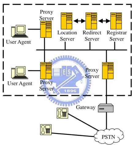
Figure 2.1 SIP network components.
2.1.1 SIP Components
SIP protocol is situated at the session layer in OSI model, and at the application layer in TCP/IP model. Henning Schulzrinne and Mark Handley have designed SIP starting from 1996. The latest version of the specification is RFC 3261 [3] from the
User Agent User Agent Proxy Server Proxy Server Location Server Redirect Server Registrar Server Proxy Server Gateway PSTN
IETF SIP Working Group. SIP components consist of User Agent Client (UAC), User Agent Server (UAS), Proxy Server, Location Server, Redirect server, Registrar Server and Media Gateway as shown in Figure 2.1.
User Agent Client (UAC)
A user agent client is a logical entity that creates a new request, and then uses the client transaction state machine to send it. UAC will last only for the duration of that transaction. If a user initiates a request, it will act as a UAC for the duration of that transaction. It assumes the role of a user agent server for the processing of the transaction if it receives a request later.
User Agent Server (UAS)
A user agent server is a logical entity that generates a response to a SIP request. The response accepts, rejects, or redirects the request. UAS will last only for the duration of that transaction as UAC. If user responds to a request, it acts as a UAS for the duration of that transaction. It assumes the role of a user agent client for the processing of that transaction, if it generates a request later.
Proxy Server
A proxy server is an intermediary entity which acts as both a server and a client for the purpose of making requests on behalf of other clients. It primarily maintain the routing of this session, which means its work is to ensure that a request is sent to another entity (Proxy Server) closer to the targeted user. Proxies are also useful for enforcing policy.
Location Server
A location server is used by a SIP proxy or redirect server to obtain information about a callee’s possible location(s). It contains a list of bindings of address-of-record keys to zero or more contact addresses. The specification defines a REGISTER method that updates the bindings.
Redirect Server
A redirect server is a user agent server that generates 3xx responses to those requests it receives, directs the client to contact an alternate set of URIs of proxy servers or callees.
Registrar
A registrar is a server that accepts REGISTER requests and places the information in those requests it receives into the location servers for the domain it handles.
2.1.2 SIP Signaling Messages
A SIP message is either a request from a client to a server, or a response from a server to a client. Request and Response messages both use the basic format of RFC 2822 [16], even though the syntax differs in character set and syntax specifics. Both types of messages consist of a start-line, one or more header fields, an empty line indicating the end of the header fields, and an optional message-body.
SIP Requests
SIP requests are the codes used by Session Initiation Protocol for initiating action such as a phone conversation. Usually it is used to invite a user to set up a communication session.
SIP Responses
SIP responses are the codes used by Session Initiation Protocol for communication. They complement the SIP Requests.
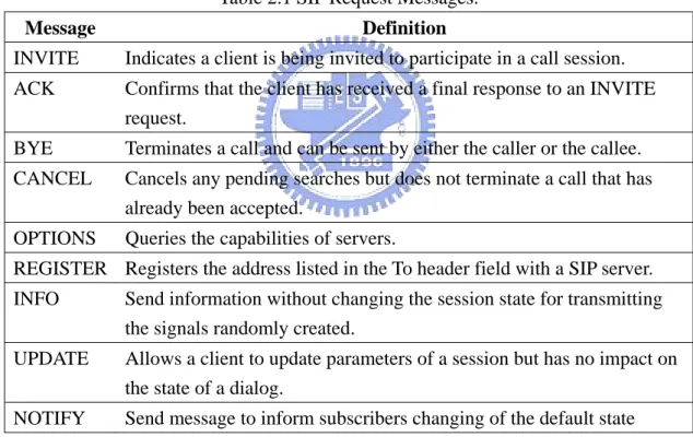
Table 2.1 SIP Request Messages.
Message Definition INVITE Indicates a client is being invited to participate in a call session.
ACK Confirms that the client has received a final response to an INVITE request.
BYE Terminates a call and can be sent by either the caller or the callee. CANCEL Cancels any pending searches but does not terminate a call that has
already been accepted.
OPTIONS Queries the capabilities of servers.
REGISTER Registers the address listed in the To header field with a SIP server. INFO Send information without changing the session state for transmitting
the signals randomly created.
UPDATE Allows a client to update parameters of a session but has no impact on the state of a dialog.
NOTIFY Send message to inform subscribers changing of the default state
Let us give an example (see Figure 2.2 below) for two users to form a call between themselves from INVITE message to BYE message.
Table 2.2 SIP Response Messages.
Method Definition 1xx: Provisional Request received, continuing to process the request.
2xx: Success The action was successfully received, understood, and accepted.
3xx: Redirection Further action needs to be taken in order to complete the request.
4xx: Client Error The request contains bad syntax or cannot be fulfilled at this server.
5xx: Server Error The server failed to fulfill an apparently valid request 6xx: Global Failure The request cannot be fulfilled at any server
2.2 Chord: an original distributed hash table protocol
The Chord protocol supports just one operation: giving a key and it maps the key onto a node. The node might be responsible for storing a value associated with the key depending on applications using Chord. The Chord protocol uses consistent hashing to assign key values onto Chord nodes. Consistent hashing tends to balance load because each node responsible for storing information receives the same number of keys, and requires relatively little changing of keys when nodes join and leave the system.
Each Chord node needs “routing” information about only a few other nodes. Because the routing table is distributed, a Chord node has to communicate with other nodes for performing a lookup. In the steady state, each node maintains information about only O(logN) [13] other nodes in an N-node system, and resolves all lookups via O(logN) [13] messages to other nodes. Chord maintains its routing information as nodes join and leave the system.
A Chord node requires information about O(logN) other nodes for efficient routing, but performance degrades gracefully when the routing information is out of date. This is important in practice because nodes will join and leave arbitrarily, and consistency of even O(logN) state may be hard to maintain. Only one piece of information per node need be correct in order for Chord to guarantee correct routing of queries; Chord has a simple algorithm for maintaining this information in a dynamic environment.
Many P2P systems use stronger peers (super-peers, super-nodes) as servers and client-peers are connected in a star-like fashion to a single super-node. The
super-nodes will be elected based on its bandwidth and capability. In Chord protocol, the supper-nodes will form the base-ring of the architecture of Chord for Kundan’s P2P-SIP to maintain “routing” information.
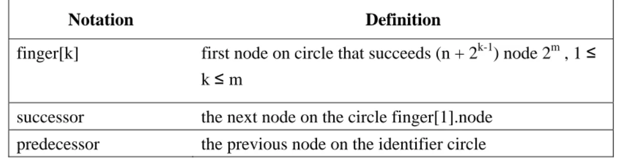
Table 2.3 Definition of variables for node n using m-bit identifiers
Notation Definition finger[k] first node on circle that succeeds (n + 2k-1) node 2m , 1 ≤
k ≤ m
successor the next node on the circle finger[1].node predecessor the previous node on the identifier circle
Consistent hashing assigns keys to nodes as follows. Identifiers are ordered on an identifier circle modulo 2m (m is the number of bits in the key/node identifiers). Key k is assigned to the first node whose identifier is equal to or follows the identifier of k in the identifier space. This node is called the successor node of key k, denoted by successor(k). If identifiers are represented as a circle, the Chord ring, of numbers from 0 to 2m -1, then is the first node clockwise from k.
Lookups could be implemented on a Chord ring with little per-node state. Each node n needs only to know how to contact its current successor node on the identifier circle. Queries for a given identifier could be passed around the circle via these successor pointers until they encounter a pair of nodes that straddle the desired identifier; these condign pair is nodes the query maps to.
Each node maintains a routing table up to m entries called the finger table. The ith entry in the table at node n contains the identity of the first node s that succeeds n by at least 2i-1 on the identifier circle, i.e., s=successor(n|2i-1), where 1 ≦ I ≦ m. The node is the ith finger of node n and denote it n.figer[i] (see Table 2.3). A finger table
relevant node. Note that the first finger of n is the immediate successor of n on the circle (for convenience we often refer to the first finger as the successor).
Figure 2.3 Lookup for key 54(a)Finger table node 8(b)Path for query key 54 [13]
The example in Fig. 2.3 (a) shows the finger table of node 8. The first finger of node 8 points to node 14, as node 14 is the first node that succeeds (8+20) mod 26 = 9. Similarly, the last finger of node 8 points to node 42, as node 42 is the first node that succeeds (8+25) mod 26 = 40.
2.3 Models of audio conferencing
This section regards various SIP multi-party conferencing models [17] [18] and discusses how they have been used and analyze their relative advantages and drawbacks in turns. This configuration focuses on SIP specification and some of its extensions.
2.3.1 Central Server
In this model, each User Agent (A, B, C, D) has a SIP protocol and RTP protocol relationship with the conference server. Each participant sends their own media information and media stream to the central server. The conference server mixes all received media streams from all participants, and redistributes the appropriate media streams back to the appropriate participants. The conference server also needs to create a customized stream for every currently active M senders and a common stream for all N-M listeners.
Figure 2.4 Central conference server model.
The central server model has the advantage that participant clients have no need to perform media summing and to modify their fundamental facilities. Besides it is simple to support heterogeneous media streams for clients, with the central conference server performing the transcoding.
B A
Σ
--->: RTP A B C SIP B+C A+C B+C Conference Server C2.3.2 Multicast
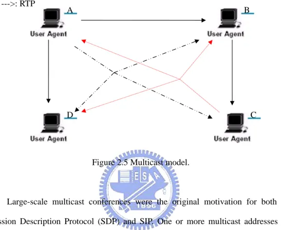
Figure 2.5 Multicast model.
Large-scale multicast conferences were the original motivation for both the Session Description Protocol (SDP) and SIP. One or more multicast addresses are allocated to the conference in a large-scale multicast conference. Each participant joins multicast groups, and sends their media streams to those groups. Signaling is not sent to the multicast groups. The whole purpose of the signaling is to inform participants the multicast groups they should join. But there are many multicast functionality disabled by routers for commercial concern today, it seems not appropriate for business availability. Now it seems intending to perform multicast using an application level multicast (ALM) protocol.
B A
--->: RTP
2.3.3 End User Mixing
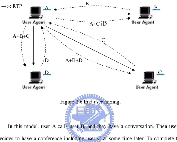
Figure 2.6 End user mixing.
In this model, user A calls user B, and they have a conversation. Then user A decides to have a conference including user C at some time later. To complete this kind of operation, it (user A calls user C) uses a fully separated SIP call. This call uses the same Conference-ID but a different Call-ID, different tags, and …etc. It is important that no call set up directly between user B and user C. A receives media streams from both user B and user C, and user A mixes them. User A sends a stream containing user A's and user B's streams to user C, and also a stream containing user A's and user C's streams to user B. User B and user C do not have to be aware of the service performed by user A, but other participants can in turn mix media stream. The following table concludes key difference in these SIP conference models.
B A --->: RTP A+B+C D C B A+B+D A+C+D D C
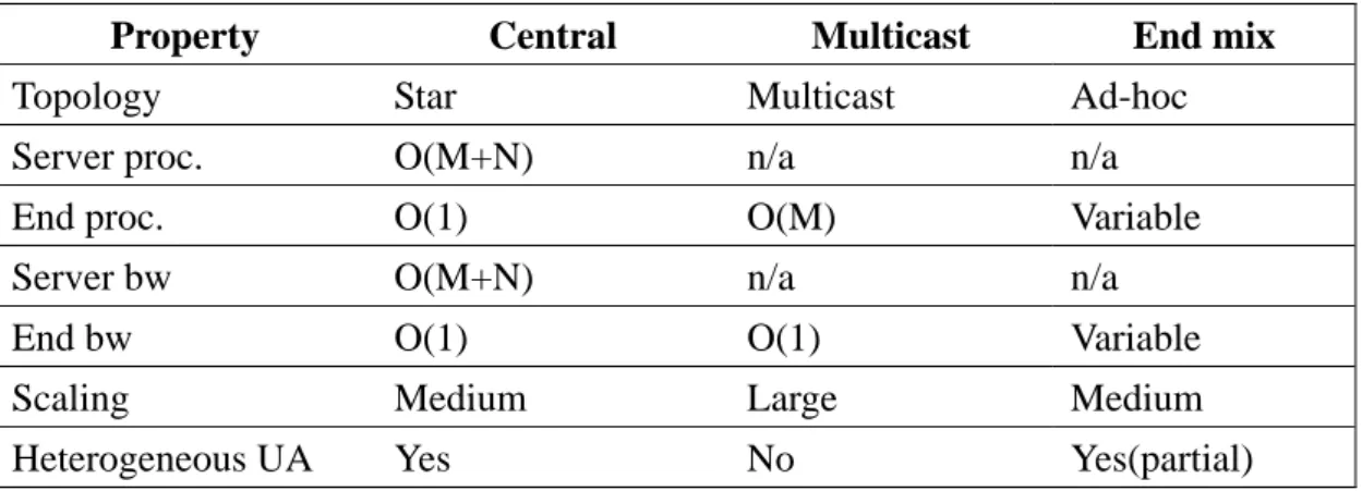
Table 2.4 SIP Conference Models Comparison
Property Central Multicast End mix
Topology Star Multicast Ad-hoc Server proc. O(M+N) n/a n/a
End proc. O(1) O(M) Variable Server bw O(M+N) n/a n/a End bw O(1) O(1) Variable
Scaling Medium Large Medium
Heterogeneous UA Yes No Yes(partial)
2.4 Full Mesh and Mutualcast Conference Control Protocol
In this section, there are two conferencing control protocol introduced for our proposed scheme. Full Mesh, Mutualcast and our proposed scheme are similar in network topology but different in mixing media streams and delivering the media frames.
2.4.1 Full Mesh Conferencing
Full mesh conferencing [14] is intended for tightly-coupled, small-to-medium size conferences (with up to, perhaps, 10 members). It will be called “conference calls” better than the larger “presentation” sessions for which the dedicated resources of a conference server or the loose coupling of a multicast conference are likely more appropriate.
Figure 2.7 illustrates this model, every endpoint directly communicates with each other. All the participants in the conference are no topologically special, or have any additional rights or abilities beyond those of the others. Any member in the
conference can invite a new user into the conference or leave the conference without affecting the remaining conference participants at any time. If a new member is accepted to enter the conference, it establishes connections to every other participant in the conference.
Figure 2.7 Full mesh conferencing.
Audio is mixed only for playing out at end points; mixed audio is never sent over the network. The primary advantage is that no end system needs to encode more than one media stream, per outgoing codec. For most voice codecs, encoding is much more computationally complex than decoding. Each participant will be decoding N-1 media streams in an N-member conference, but needs to encode only one. But each user must have the bandwidth available for sending N-1 simultaneous streams in an N-member conference. Thus, this protocol is not appropriate for bandwidth limited end systems such as wireless devices, users with 56 kb/s modems, or users with asymmetric DSL connections with low upstream bandwidth, and they do not scale well to large conferences.
B A A D C B A A B C C D D B D C
Table 2.5 Full mesh protocol messages
Protocol SIP Definition
JOIN INVITE invites a new member to join a conference CONNECT INVITE establishes connection between two endpoints
which are already members of the conference. LEAVE BYE terminates a dialog, regardless of how the
dialog was established.
UPDATE UPDATE informs a party of new information about the conference membership list.
JOIN OK 2xx: Success indicating JOIN request was accepted JOIN Ack ACK indicating OK was received
JOIN Reject CANCLE indicating JOIN request was refused
CONNECT OK 2xx: Success indicating CONNECT request was accepted CONNECT Ack ACK indicating OK was received
CONNECT Reject CANCLE indicating CONNECT request was refused
Protocol messages are sent within the context of control and dialogs. A dialog is a communications session between two end systems. It corresponds to the existence of bidirectional media exchange between the end systems. Every dialog is identified by a globally unique dialog identifier. Additionally, every conference has a globally unique conference identifier. A conference dialog falls within exactly one conference.
2.4.2 Mutualcast conference control
In full mesh conferencing topology, each peer needs (n-1)‧bw upload bandwidth to send the audio streams to other peers, and a maximum of (n-1)‧bw download bandwidth to receive the incoming audio. This places a big burden on each peer and the entire network.
A key characteristic of MutualCast [15] is that it rotates the mixing and redistributing tasks among participants for sharing network bandwidth and
computation load.
Figure 2.8 Mutualcast conferencing [15].
A sample MutualCast audio mixing session for three peer nodes 1, 2 and 3 is shown in Figure 2.8. By audio mixing schedule at the bottom of the list, the peer nodes 1, 2 and 3 are engaging in audio mixing and redistribution at frames 3k, 3k+1 and 3k+2, respectively. At the 1st frame, the peers 1 and 3 send their coded audio p1,1
and p3,1 to peer 2, and peer 2 mixes and redistributes the audio packets. In order to
avoid echo, the source audio stream is not mixed and sent back. By time-sharing the mixing and redistributing task, the bandwidth and computational cost of the mixing is distributed among the peers.
Chapter 3 Proposed Approaches
According to our survey of many kinds of SIP conferencing models, some problems will be addressed. These include that conference setup is slow and how users could be aware of an existing conference through the Internet. Here we propose a simple mechanism that features the benefits of various conferencing models. It contains three kind of modes-dial-in, dial-out and freely get into the conference. The mechanism focuses on the small-to-medium audio conference and the number of the participants will be 10 at most.
Figure 3.1 Kundan’s P2P-SIP Architecture [11].
In addition, which conferencing control protocol is better for us to adopt to construct a P2P audio conferencing session? It is to enhance the Mutualcast which carries advantages of full mesh conferencing and lower upload bandwidth to a simple and much lower bandwidth utilization system by using the relay nodes to transfer
mixed frames.
Before addressing our proposed schemes, firstly we interpret the architecture of Kundan’s P2P-SIP [11], which will be utilized in our proposed approaches. Figure 3.1 shows the architrcture.
In Figure 3.1, it shows the block diagram of the different components in the P2P-SIP node as described in the following:
z User interface
It interacts with the user, keeps tracking of his “buddy list” and invokes the user location module to know where the users are.
z User location
It can invoke the user interface module, the SIP module or, if this node is a super-node, the DHT module to locate the user.
z Registration
It activates to initiate peers discovery and SIP registration, when a node starts up and a user signing in with his identifier.
z SIP
SIP is used as the underlying protocol for locating another user, registering the user, and call setup. Once a lookup of user location is done, the call setup can be sent directly via the SIP module.
z DHT
When the node is a super-node, it maintains the information of DHT peers (such as Chord finger table) and perform DHT functionalities.
z Media path
The media path (such as audio device, codecs and transport) is largely separated with the P2P-SIP operation. And this will be integrated with our
3.1 Proposed Quick Conferencing Setup
When an end user is going to create an audio conference in a Peer-to-Peer system, he should already be aware of the information about the members of this audio conference including other members’ locations, the bandwidth of the other members and properties of all media streams. Then this end user will dial-out to all the members he wants to invite into the audio conference. This type for forming an audio conference gets acceptance of the most popular VoIP software-Skype.
All members who intend to participate in this audio conference must pre-know the location or the phone number of this audio conference and then in a particular appointed time all members of the audio conference dial-in to the conference founder to begin an audio conference in contrast.
The last method for creating an audio conference is that participants of the audio conference may join the proceeding conference any time. When an audio conference is activated, each user knowing the location of the members of the audio conference can join the conference or every member of the audio conference can send the invitation to any end users to invite them joining the conference, much similar to full mesh conferencing protocol.
In brief, all the aforementioned modes have one important key in common that is the location of users. No matter dial-in, dial-out or P2P modes they all have to be aware of the location of the participants who intend to join the audio conference, or the founder of the audio conference. Our proposed quick conference setup scheme definitely focuses on the location of the participants of the audio conference including the founder and the others who intend to join the conference.
Three parts of our proposed scheme just resemble the modes mentioned above- dial-in, dial-out and P2P, but we integrate this three modes into one simple mechanism. It calls the user who creates the audio conference “the founder” which looks more like a rendezvous place.
Figure 3.2 Create an audio conference: (a) super-node (b) founder.
Setting up an audio conference needs to perform functions one by one, initiation, mode verification and start the audio conferencing, and initiation for both the founder
Create an audio conference A which modes dial-in dial-out P2P quick start start Time expires Send NOTIFY Incoming NOTIFY update internal Supernode info. choose relay nodes and backup nodes send NOTIFY to the other super-nodes Founder of audio conference (on transition from node to super-node)
A waiting for participants yes no Supernode Super-node (a) (b)
and super-node of the founder, mode verification for the founder to choose a mode and after all the audio conference starts. The next paragraphs explain the details of the functions.
3.1.1 Initiation
This section and next section describe the P2P mode (much similar to full mesh protocol) regarding how this mode works and what the benefits it has. In addition, some initial processes of the founder and super-nodes have to be done in order to create an audio conference using our proposed scheme.
When a particular user wants to create an audio conference, there are two assignments triggered. One is that the founder will send a NOTIFY in SIP message to his super-node of P2P system and the founder information will be stored in the conference list created by DHT. The conference list has duplications in every super-node to inform new users connecting to the P2P network. Another is that super-node will receive the NOTIFY message and begin to arrange the deployment (see the left side of Figure 3.2). These events also happen in other two modes for the initiation of creating an audio conference.
The super-node will send out the NOTIFY message to other super-nodes to notify other users who are under control of other super-nodes that there is an audio conference created when it receives the NOTIFY message, which is from the founder of an audio conference. The super-nodes will also arrange the relay nodes and the relay backup nodes for the audio conference and inform the founder of the audio conference what nodes could be the candidates of the relay nodes.
z Communication tag
The tag labels that the user is busy in communication with another user, including the users in any audio conference.
z RTT
Choose the nodes with the minimal RTT.
At first, the super-nodes will abandon the nodes with the communication tag on, because the nodes are considered too busy to process the works of a relay node. The major norm has to be measured to elect the candidates of the relay nodes in both the DHT side and the founder side. The super-nodes of DHT measure the RTT (Round Trip Time) in OPTIONS message and elect the nodes of the minimal RTT between the super-nodes and nodes to become the candidates of the relay nodes. Then super-node of the founder will inform the founder the candidates in OPTIONS message and the founder will measure these candidates in OPTIONS message to get an appropriate one of the RTT (minimal for sure) and the capacity of the candidate nodes.
The founder receives the relay node list by OPTIONS message from his super-node, and then the founder could choose any nodes in the list or by measuring the nodes of the relay node again to elect the best node. Regarding what situation the system will use the relay nodes for transmitting the media streams is presented in Section 3.2.
3.1.2 P2P Mode
If the founder choose the P2P mode in the initiation of creating an audio conference after sending the NOTIFY message to super-node, the audio conference
the founder will wait for the users sending the JOIN message to him and sending the CONNECT message back to the users, sending the JOIN message to make them becoming the participants of the audio conference. The maximal numbers of the participants is up to 10 for a small-and-medium size audio conference, thus the founder will only allow 10 participants at most in the audio conference the founder created, and discard the subsequent joining users. And our simulation will present that 10 participants is the maximal numbers of the participants in an audio conference.
Figure 3.3 P2P mode signaling delivery.
The participant of the audio conference can invite any users in the Peer-to-Peer network as well as in the Full mesh conferencing model (see the Figure 3.3). The participant can look up the location of the user he intends to invite, and use the JOIN message to inform the user where the founder of the audio conference is. After this occurrence, the permission of joining the audio conference is controlled by the founder who can decide whether to allow a user to participate in the audio conference.
Founder Participant Super-node User I Lookup for User I
Location of User I
JOIN message CONNECT message
If the user joining is permitted, the founder will send CONNECT OK message including the information of the other participants (such as location and properties of media stream), otherwise it sends CONNECT Reject message to deny the user from the audio conference. The founder will automatically discard the user by using CONNECT Reject message to inform the user intending to join if the number of users in the audio conference reached the limit.
3.1.3 Dial-in and dial-out modes
Dial-in mode and Dial-out mode are much similar to their operations, the only and large difference of these two modes is apparent to their appellations. In contrast, they all need the participants to make an appointment in a particular time, and then they would dial in or out a number simultaneously to form an audio conference at the time they appointed. Thus these two modes will be integrated including the P2P mode into the one scheme we proposed.
It can start the audio conference immediately if the founder dials out a number list of the participants he already knew the locations and it will transform the audio conference into the P2P mode. The founder also can wait for the users signing in even the founder already knew a location list of the users he wants to invite after he send the NOTIFY message to the DHT for notifying the other users on P2P network. The NOTIFY message will inform the users where the founder is and when the audio conference will start. For dial-out mode, the founder will store a member list created at the beginning that the founder started waiting for recording the properties of the signing-in users (the most important one is the location of a user). For dial-in mode, the founder utilizes the NOTIFY message to communicate with users who have the
In the dial-out mode, when the time the founder set at the beginning of creating the audio conference expires, the founder will choose at most 10 members of the audio conference and dial out to them; for the dial-in mode, the users intending to join may dial in simultaneously so the founder should abandon some users if number of dial-in users exceeds 10. For both two modes, once the audio conference is established, the conference will be transformed into P2P mode immediately. If there is no user who intend to join the conference the founder created, the founder has two methods for operation. The founder can just abort the whole audio conference and shut it down. The other method is that the audio conference mode will be transformed into P2P mode regardless of the number of users intending to join.
Figure 3.4 Procedure of dial-in and dial-out mode. Create an audio
conference A
dial-in and dial-out
dial-in or dial-out Send NOTIFY Founder waiting for participants yes no P2P time expire dial-out
What have been addressed in this paragraph is that the users are noticed by NOTIFY message DHT sent in all modes of our proposed mechanism. That is important because many users may not be aware of an audio conference being setup. And it will cause the users who intend to join the specific audio conference to miss the opportunity of joining.
3.2 Proposed Audio Conferencing Protocol
The Mutualcast mentioned above is our basic audio conferencing protocol. Although the media path of Figure 3.1 is separated from the main architecture, it still plays a substantial role as a whole. And our proposed conferencing control protocol is directly compatible with the media path module of Figure 3.1. There are some problems which the author of Mutualcast audio conferencing protocol did not address definitely. We focus on the most important problem-Packet loss rate and propose an enhanced protocol.
The problems and their improvements are addressed in the following: z Packet may get lost before mixers receive it.
z Packet may get lost after mixers delivered it.
Packet get lost before mixers receive it
The compressed audio is split into frames by the encoder and these frames are cut into pieces to match the appropriate size of the packet. Then the audio media stream would be delivered through RTP [19] (Real-time Transport Protocol). As a result of RTP on the top of UDP, packets delivered between peers who are participants
nodes failure of routing path, traffic congestion, and packet collisions. And packets loss could be worse if the number of peers increase and number of packets exponentially boosted in the Mutualcast conferencing control protocol.
Unlike TCP, UDP used by RTP will do nothing on packets loss and it looks the same as in the Mutualcast. It will be grisly if there are packets lost in the Mutualcast, because one lost packet means that the other packets in the mixer would be discarded likely. If the mixer discards all packets in the buffer queued for only one packet loss, the quality of voice will become worse due to the increased participants of the audio conference.
In order to solve this problem, it is suggested to force the mixers to mix the appropriate frames in the buffer queue and skip to receive remaining frames considered as packets lost for a limited period. The period is difficult to demarcate because the packets probably delay too long or transship by too many steps. Nevertheless, it is well known that in order to allow natural conversation, the mouth-to-ear latency of a voice-communication should not exceed 300 ms [20]. Thus we assume that if all appropriate packets are not collected in time, the mixers should buffer frames until the timer clocks exceed 200ms for eliminating the packet propagation time between participants of the audio conference and improving the quality of voice.
Packet gets lost after mixers delivered it
After the mixers send out packets of mixed frames, it is still unreliable for delivering on the network according to the properties of UDP and the increased traffic load results in packet loss of mixed frames. For more robust delivery rate, the relay nodes we mentioned in Section 3.1.1 are introduced to achieve our purpose.
conferencing control protocol except relay node and backup node. Let us explain how this method operates by taking Figure 3.5 as an example. The improved Mutualcast will form a clique connection of 5 nodes including 4 participants of the audio conference and 1 relay node, and schedule the mixer order of 4 participants (bottom of the figure 3.5). At first all participants except user A will send their first packet (frame) to user A (the first mixer), and when user A receives all first packets from other participants, he will mix the frames by his decoder and copy the mixed frame to send to relay node. The mixed frames will include all the participants’ first frame (such as the first mixed packet: Pa,1+P b,1+P c,1+P d,1) and be redelivered by relay node
to all of the participants except the mixer who sends the packet to relay node. Participants use their decoders to eliminate their echo in the mixed packets (user C should eliminate P c,1 in Pa,1+P b,1+P c,1+P d,1).
B A C D … Time 1 2 3 4 5 6
Peers mixing schedule user A user B user C user D user A user B Pa,4 Pd,1 Pc,4 Pb,3 Pc,2 Pd,3 Pb,1 Pa,2 Pd,2 Pb,4 Pc,1 Pa,3 Relay Backup
Figure 3.5 Improved Mutualcast conferencing media stream control protocol.
The backup node will be operating only when the relay node failed. The founder should be aware of the failure of the relay node by checking RTCP [19] report for the relay node in a regular period. Moreover the number of the relay nodes will be up to 3 for alleviating the traffic load to the relay node.
In Chapter 4, simulation results demonstrate the improvement of our proposed system and packet loss is reduced as well.
Silence suppression
Silence suppression is an important functionality in VoIP, because a person will not speak from beginning to end in the audio conference or two party communications. When a participant stops delivering his voice frame after he finishes his speech, it turns to the other participants to talk. In Mutualcast, we can assume that the functionality of silence suppression is not used at all in order to deliver the sequentially numbered packets which are marked by each peer respectively.
For this scenario, we use a blank packet to substitute the original unknown approach and the packet will just inform the mixer that participant is silent and no need to decode the voice frame in packet for that participant.
3.3 Mathematical Analysis
In this section, we will analyze the packet delay in the original Mutualcast and in the improved system we proposed. In the original Mutualcast [15], let the packet propagation delay between the participant node i and j be di,j. Assuming the delay
caused by the mixing operation can be ignored, the packet delay of the user i receiving an audio frame mixed by peer k can be calculated as:
(1)
The maximum packet delay when the user i receives the packet can be calculated as:
(2)
And the maximum delay of the original Mutualcast is:
, (3)
It is two times the packet propagation delay of the farthest peer pair in the original Mutualcast clique.
In our proposed system, let the packet propagation delay between the participant node i and the relay node r be Ri,r , the packet delay of the user i receiving an audio
frame mixed by peer k can be calculated as:
(4)
The maximum packet delay when the user i receives packet can be calculated as:
(5)
And the maximum delay of the improved scheme is:
(6)
which is likely smaller than two times the packet propagation of the farthest peer pair in the original MutualCast clique because the relay nodes we selected have more power and less delay with superior bandwidth.
Now we consider an n-party conferencing session. For a three nodes (participants) conferencing session with star topology, it needs a node with at least 2bw bandwidth to form a multiparty conference. In the Mutualcast, each participant sends and
+ Rk,r + Rr,i Rk,r + Rr,i + max Rk,i r≠ k≠i ≦
during n-1 frames which do not perform the mixing operation among 2(n-1) packets. The upload/download bandwidth required is up to (2-2/n)•bw. The Mutualcast requires the (2-2/n)•bw upload/download bandwidth for each user node if all participants have the equal bandwidth. For a three nodes Mutualcast clique in instance, the bandwidth required is 1.34bw. Moreover our proposed scheme will be superior in the utilization of bandwidth. Each participant still sends and receives 2(n-1) packets every n frames. There are n packets sent after performing the mixing operation and they will be delivered to the relay nodes and be redelivered to every participant. Therefore the bandwidth requirement of every participant will be reduced to 1•bw for distributing the traffic load to the relay nodes.
3.4 Summary
In this chapter, a new setting up conference mechanism which integrates the benefits of the centralized server model, and end-user mixing models has been presented. This mechanism not only takes the advantages of existing models but also utilizes the advantages of the Peer-to-Peer network. But the previous existing models did not utilize these advantages. Utilizing the Peer-to-Peer network (Chord) in the audio conference is rare in many related researches. Our new mechanism for setting up a conference is not operated individually like three separate modes: dial-in mode, dial-out mode (centralized server) and P2P mode (end-user mixing); instead, these modes will interact with each other.
Second, an improved conferencing control protocol extended from Mutualcast audio conferencing control protocol solves some problems such as packets loss and congestion in the original Mutualcast over the Internet. And it comes with a simple
mathematical analysis of our improved conferencing control protocol, and analysis points out the improvement on reducing the total number of packets by separating the mixed packets from original path to another path. The performance verification will be presented in Chapter 4 including packets drop, throughput and packet delay.
Chapter 4 Simulation and Numerical
Results
Simulation will show the performance of our proposed scheme, and observation of the results of simulation will reflect the improvement between our proposed scheme and the original Mutualcast. The audio conference setting up is difficult to measure, so we focus on the audio conferencing media streaming control protocol only. In this chapter, simulation environment will be introduced first and then the simulation results and analysis will be interpreted in turn.
4.1 Simulation Environment
In order to demonstrating the performance of our proposed scheme, we use NS-2 (version 2.31) tool [21] and the ns2VoIP module [22] which has been developed by the Computer Networking Group of the Information Engineering Department of the Pisa University, Italy. For simulation convenience, it has to fix and adjust the NS-2 and the ns2VoIP module to match the original Mutualcast conferencing control protocol and our improved Mutualcast. Our simulation network topology is presented in Figure 4.1. Our proposed improved conferencing control protocol will utilize the relay nodes to retransmit mixed frames from mixers.
There are some simulation assumptions to be set constantly to compare the difference between two protocols. The ns2VoIP will be tuned to constant bit rate (CBR) like in order to build multiple sessions of audio conferencing without silence
suppression. VoIP traffic without silence suppression, with format of G.711 codec, 160 bytes payload and 20ms intervals (64kbs) will be the basis for the encode/decode media streams in both original Mutualcast and our proposed improved conferencing control protocol, and numbers of relay nodes used by members of the audio conferencing is listed in Table 4.1. The number of relay nodes will grow up with the increasing members of the audio conferencing. Additional relay nodes are used in order to separate the traffic load on a network bottleneck and to reduce the individual upload bandwidth. And the simulation results will be presented and analyzed in Section 4.2.
Figure 4.1 Simulation network environment.
Table 4.1 Simulation of using relay nodes parameters
Protocol 3 4 5 6 7 8 9 10 Mutualcast no no no no no no no no
Internet
G.711
160Bytes/64Kbs
VoIP without silence suppression
Relay nodes
only for improved method
Peer Peer Peer Peer Peer Peer
4.2 Simulation Results
It should be clear in our simulations environment of NS-2 and ns2VoIP before addressing simulation results and analysis. Since Mutualcast audio conferencing control protocol is a rough prototype presented on a conference and Mutualcast is proprietary, we imitated the Mutualcast protocol according to its algorithm and encode/decode of ns2VoIP module. Although there might be some deviations in our simulations from actual scenarios, the subsequent simulation results will show the performance improvement of our proposed conferencing control protocol.
4.2.1 Packets drop
The unmixed packets and mixed packets will both be counted into total amount of the packet loss. If the unmixed packets are lost, the mixed packets will not be delivered in original Mutucalcast and will cause long packet delay in our proposed scheme. If the mixed packets are lost, the quality of service will be intolerable in both original protocol and our proposed scheme.
In our packets drop simulation, the members of the audio conference will start from 4 members to 10 members. It is the same for 3 members in original protocol and our proposed protocol. And our proposed protocol will use relay nodes (in Table 4.1) for distributing upload traffic load on user nodes switching to relay nodes.
Table 4.2 illustrates the comparison of the packets drop between the original scheme and our proposed scheme. Packet loss rate are calculated as the ratio of total packets dropped divided by total packets sent. It will be the index of the quality of
service of voice delivery.
Table 4.2 Simulation Result of Packet Drop Packet Drop (%)
Nodes Original Proposed 4 0 0 5 0 0 6 1.17% 0 7 3.43% 0 8 6.88% 0.22% 9 8.03% 2.74% 10 10.27% 6.59%
According to the packet drop data illustrated in Figure 4.2, our proposed audio conferencing control protocol has a significant improvement compared to the packet drop in original Mutualcast. In Figure 4.2, our proposed scheme causes the packet drop in 8 nodes and strikingly packets drop from 9 nodes to 10 nodes. In contrast, the original Mutualcast has strikingly packets drop from 6 nodes to 10 nodes and it is consistent with the report of the original Mutualcast conferencing media stream control protocol [15]. The original Mutualcast are capable of tolerating the members of the audio conference up to seven members. In original Mutualcast, when the members of the audio conference grow up to 10 members, its packet drop rate will rise up to 10.27% and that means out of 9 unmixed packets delivered to appointed mixer on the network, one packet will get lost. It is a serious problem because the mixer in turn could not receive all appropriate unmixed packets, and one way to solve this problem is to drop all unmixed packets in buffer at a time for the original Mutualcast, and another is buffering all unmixed packets until the time we consider the packet(s) lost expires. Even though it is not always the unmixed packet loss, the
0 2 4 6 8 10 12 1 2 3 4 5 6 7 8 9 10 11 數列1 數列2
Figure 4.2 Simulation result of packet drop.
10 members participating in an audio conference is a bottleneck in our proposed conferencing scheme (in the original Mutualcast as well) because excess of packets will be delivered on the simulation network and handled by the appointed mixers. The peer nodes upload bandwidth and the bottleneck of the simulation network will be congested with the excess of packets. Packet loss for both unmixed packets and mixed packets, will affect mixed-packet loss and voice delivery quality of the audio conference. And packet loss will also affect the throughput of the audio conference in both original Mutualcast and our proposed scheme. The next section focuses on the throughput which is also an index for quality of service in audio conference.
Improved Original
nodes
4.2.2 Throughput
In this section, the throughput and the behavior of mixed packets are analyzed only to simplify the simulations because the mixed packets play an important role in original Mutualcast and our proposed conferencing control scheme. And relations are analyzed between the throughput and numbers of members in the audio conference and packets dropped.
Table 4.3 Simulation result of throughput Throughput (Kbit/s)
Nodes Original Proposed
4 767.1496 769.3552 5 1278.5827 1281.5329 6 1571.2307 1920.6115 7 1304.0548 2688.0913 8 1195.3364 3136.2000 9 775.3169 2305.7397 10 489.4176 1353.2886
Table 4.3 illustrates comparison of throughput of the mixed packets delivered on the simulation network between the original scheme and our proposed scheme. In Table 4.3, the throughput is the total sum of the mixed packets which all nodes received, and it uses kilo bits per second as the unit of the throughput measurement in our throughput simulation. Analysis of 4 and 5 members in audio conference shows that the original Mutualcast conferencing control protocol and our proposed scheme are similar for a smooth traffic on the simulation network until 6 to 10 members in the original Mutualcast and 9 to 10 members in our proposed scheme, and it is consistent
According to the throughput data illustrated in Figure 4.3, our proposed audio conferencing control protocol has a much better throughput improvement compared to the original Mutualcast until the members in the audio conference is close to 9 and 10. When the participants of an audio conference come to 7, 8 and 9, it is apparent that there is a great difference in the throughput. Even though the throughput of 10 members participating in an audio conference is not excellent as before (less members in an audio conference), our proposed conferencing control protocol features doubled throughput of the original Mutualcast protocol.
0
500
1000
1500
2000
2500
3000
3500
1
2
3
4
5
6
7
8
9
10
11
數列1 數列2Figure 4.3 Simulation result of throughput.
The inferior throughput follows the packet drop and comparison of Figure 4.2 and Figure 4.3, it should be clear that the relation of the throughput and the packet loss. With high packet loss rate, it will result in the inferior throughput especially at 10 participants in an audio conference with an excess of the unmixed and mixed packets.
Improved Original
Throughput
4.2.3 Packet delay
Packet delay is important for the VoIP traffic and its advanced application in audio conferencing because the longer the packet delay, the lower the quality of service that users can feel. The long packet delay also leads to the asynchronous communication in an audio conference with a large number of participants.
Table 4.4 Simulation result of packet delay Packet Delay (ms)
Nodes Original Proposed 4 37.047 43.832 5 36.755 44.538 6 43.885 46.117 7 43.383 48.407 8 43.709 48.640 9 42.321 46.130 10 42.245 46.316
Table 4.4 illustrates comparison of packet delay of the mixed packets delivered on the simulation network between the original scheme and our proposed scheme. Only mixed packets are emphasized because the mixed packets are more important than the unmixed packets. In Table 4.3, packet delay of the original Mutualcast conferencing control protocol is better than the delay of our proposed conferencing control protocol because of the utilization of relay nodes which receive the mixed packets from mixers and retransmit them to participants. It causes a little longer packet delay in our proposed scheme for using the relay nodes.
Mutualcast in our simulation. It is well known that in order to allow natural conversation, the mouth-to-ear latency of a voice-communication should not exceed 300 ms [20].
30
35
40
45
50
55
60
1
2
3
4
5
6
7
8
9
10
11
nodes
ms
數列1
數列2
Figure 4.4 Simulation result of packet delay.
In our proposed scheme, the packets delay of 9 members in an audio conference descends slightly as compared with the 8 members in an audio conference because the packet loss results in less mixed packets being delivered along the path between mixers and relay nodes. While packets delay of the original Mutualcast conferencing control protocol is mitigating starting from 6 members to 10 members participating in an audio conference because the packet drop occurred, and it means the simulation network is congested by the excess of packets. This makes the packets delay increased to the largest value in the simulation.
4.3 Summary
In Chapter 4, the comparison of the original Mutualcast conferencing control protocol and our proposed improved Mutualcast scheme is presented and the simulation results show the improvement on packet drop and throughput with a little cost of the packet delay.
To reduce the traffic, both received and delivered packets along the path between the mixers and participant is what our proposed scheme addresses, and simulation results of the packets drop and throughput approved our improved approach. Low packet drop rate and high throughput is the major improvement of our proposed scheme and on the other hand the longer packets delay must be solved.
Chapter 5 Conclusion and Future Works
In this thesis, we proposed a simple audio conferencing system including a new mechanism integrated into Peer-to-Peer network for setting up an audio conference and an improved conferencing media streaming control protocol for a pure Peer-to-Peer like media streaming control protocol-Mutualcast.
Setting up an audio conference is a pre-process in our proposed scheme even for all audio conferences, so establishing an audio conference will always take a while and participants are unable to do anything during this period of time. Eliminating or reducing the time wasted on setting up or speeding up the gap between users joining and starting to communicate with other participants is worthy to study, but setting up is ignored by most studies.
Our proposed scheme integrate three major conference modes, dial-in, dial-out (central server mixing) and P2P (end-user mixing), into a new mode with Peer-to-Peer network which is not utilized by previous three modes. In this new mode of setting up an audio conference three previous modes will interact with each other as well as with Peer-to-Peer network, they are not individually operating. It would reduce partial wasted time in certain scenarios.
An improved audio conferencing media streaming control protocol originated from the Mutualcast [15] is proposed. Our proposed protocol reduces the amount of packets a participant has to upload by deploying relay nodes which switch the delivery path of the mixed packets. Our scheme is evaluated by simulation in the aspects of the packet dropped and throughput.
![Figure 1.1 VoIP common topology connection. [27]](https://thumb-ap.123doks.com/thumbv2/9libinfo/8014393.160588/13.892.261.658.544.862/figure-voip-common-topology-connection.webp)
![Figure 2.2 Simple SIP signaling for inviting a call. [3]](https://thumb-ap.123doks.com/thumbv2/9libinfo/8014393.160588/22.892.132.758.136.480/figure-simple-sip-signaling-inviting-a-call.webp)
![Figure 2.3 Lookup for key 54(a)Finger table node 8(b)Path for query key 54 [13]](https://thumb-ap.123doks.com/thumbv2/9libinfo/8014393.160588/25.892.139.767.229.493/figure-lookup-key-finger-table-node-path-query.webp)