A Study of Impurity State and its
Implication in Inorganic and Organic
Semiconductors
Chi-Ken Lu
Institute of Physics
National Chiao Tung University
Abstract
In this thesis we deal with a few problems related to the presence of impurity in semiconductors. The focus of Part I is on the realization of THz radiation in solid state system by using the concept of resonant state, a hybrid state of localized impurity state and a band of continuum. The previous proposal on such resonant state laser, however, has a serious constrain on the applied strain, and consequently the emitted photon has a lower bound of energy. We invent a quantum well structure in order to relax such constrain and generate photon of energy less than 4 meV, corresponding to frequency of 1 THz, with feasible conditions of strain, impurity concentration, electric field, and temperature. We demonstrate that a population inversion can be achieved in this structure by numerically solving the Boltzmann kinetic equation in momentum space.
Part II is devoted to the investigation of the effects of oxygen adsorption on the electronic properties of conjugated polymers. It is found that the oxygen molecule has the tendency to adsorb onto the category of carbon-based materials with sp2-binding, such as carbon nanotube and most of the
conjugated polymers, by a weak intermolecular interaction. There are two outstanding questions regarding such adsorption. One of them is the huge mobility difference between hole and electron in many conjugated polymers. This is in contrast to the situation for the crystalline inorganic solids in which the electrons have a larger mobility than the holes. The simple formula for the carrier mobility in terms of effective mass and scattering time is apparently invalid to explain such imbalance in such disorder system because accurate band structure calculation reveals two similar effective masses for conduction and valence bands. Therefore it is the presence of defect that dominate the transport in such disorder system, and hence the observed mobility is influenced by the trap density to a great extent. The ultimate entity for such imbalance is shown to be the adsorbed oxygen molecule which causes a pair of asymmetric binding energies for the trapped electron and hole in a symmetric electronic system.
P-doping by the adsorbed gas molecule is another interesting property
of conjugated polymers. A reversible increase of conductivity is found in the polymer FET when the polymer was previously exposed to air for a few hours. The increase of conductivity, however, causes the degrade of the device characteristics by increasing the off-current. This effect can be completely eliminated by just evacuating the devices for a long time, say a week. The doping mechanism remains unclear because of the conditional illumination.
For polythiophene, the doping can be found in both dark and illumination, while it is only possible under illumination for pentacene. We would like to understand the mechanism for such doping process. Polythiophene is taken as an example by calculating the band structure for the oxygenated poly-thiophene with a self-consistent tight-binding scheme. The coincidence of Fermi level and the valence band edge reveals that a cluster of adsorbed oxygen molecules transform the semiconducting polymers into metal. Such coincidence is shown to depend on the HOMO level of the host. In addi-tion, an excitation corresponding to electron transferring to the adsorbate is also found in the band structure. The metal-insulator transition explains the doping in dark and the charge transfer excitation is interpreted as the photoinduced doping.
Keywords: THz radiation, solid state laser, resonant state, Boltzmann ki-netic equation, continuum-trap system, conjugated polymers, organic semi-conductor, quasi-particle, polaron, soliton, exciton, quantum yield, defect, trap, mobility imbalance, molecular oxygen, adsorption, metal-insulation transition, oxygen doping, Fermi level alignment.
Contents
I
Realization of THz radiation in solid state system
3
1 Overview of solid-state THz source 4
1.1 Introduction . . . 4
1.2 Quantum cascade laser . . . 5
1.3 Bloch oscillation . . . 6
1.4 Strain-induced resonant state laser . . . 8
2 Resonant state laser in quantum well structure 11 2.1 The limit on photon energy in RSL . . . 11
2.2 A remedy: QW-RSL . . . 12
2.3 Mechanism for population inversion . . . 13
3 Theoretical modeling of population inversion in a continuum-trap system 16 3.1 Hybridization of acceptor impurity state and valence band continuum . . . 16
3.1.1 Subband and Impurity Wavefunctions . . . 16
3.1.2 Resonant transition . . . 21
3.2 Carrier kinematics in the steady electric field . . . 23
3.2.1 Hole Statistics at equilibrium . . . 23
3.2.2 Boltzmann Kinematic Equation . . . 24
3.2.3 Impact Ionization and thermal recombination rates . . 27
3.2.4 Hole population in subband and lower localized accep-tor states . . . 30
3.3 Population inversion in quantum well resonant state laser . . . 33
3.4 Concluding Remarks . . . 38
4 Appendix 41 4.1 Algebraic formulation of resonant state . . . 41
II
Implication of oxygen adsorption on the electronic
properties of conjugated polymers
43
5 Theoretical backgrounds for organic semiconductor physics 44 5.1 H¨uckel model for one-dimensional lattice and spontaneous
sym-metry breaking by phonon interaction . . . 44 5.2 Polaron and soliton . . . 49 5.3 Excition and the quantum yield in light-emitting polymers . . 51
6 The unbalancing effect of adsorbed oxygen molecules on elec-tron versus hole transport in conjugated polymers 53 6.1 Overview of experimental findings on the unbalancing carrier
mobility . . . 54 6.2 Electronic structure for defect levels in conjugated polymers . 55 6.3 Electronic configuration for oxygen molecule and the
inter-molecular force . . . 56 6.4 Asymmetric binding energies for the trapper carriers emerging
from the symmetric electronic system . . . 58 6.5 Concluding remarks . . . 63 7 The p-doping by oxygen molecules in organic
semiconduc-tors 65
7.1 Overview of the p-doping in organic semiconductors . . . 66 7.2 Metal-insulator transition in the oxygenated single-wall
car-bon nanotube . . . 67 7.3 Electronic structure for oxygenated polythiophene . . . 71 7.4 The p-doping in the condition of dark and illumination . . . . 76 7.5 The Fermi level alignment in the presence of the oxygen band 79 7.6 Concluding remark . . . 80
Part I
Realization of THz radiation in
solid state system
Chapter 1
Overview of solid-state THz
source
1.1
Introduction
Applications of electromagnetic radiation are ubiquitous in our daily lives from personal communications, microwave ovens, to X-ray in medical de-tections. For scientific studies, those radiations can be used to unravel the underlying structures of tiny objects ranging from the elementary atoms, molecules, to tissues. THz radiation, whose frequency (1−10 THz) falling in the range between infrared and microwave regions of the spectrum, has a wavelength (30−300 µm) comparable to the size of human tissues and hence it is very desirable for medical imaging such as detecting cancers or other diseases. Despite of the wide applications, THz frequencies are among the least developed electromagnetic spectra. The underdevelopment is primarily due to lack of convenient THz sources that can provide high radiation inten-sities with cw operation. Radiation sources based on solid state media are thus highly desirable due to its size and the potential integration with other electronic applications. However, it is difficult to achieve the population in-version conditions for this range of frequency in solid state system because some thermal processes, like acoustic phonon scattering and Auger relax-ation, inherent for solids have energy scale of meV, and hence can equalize non-equilibrium carrier distributions of states spaced by a few THz.
Since the original proposal of semiconductor superlattices, there has been much progress to obtain optical gain in such novel system. In this chapter we are going to review three different schemes to generate THz radiation based on the solid state quantum structures. For quantum cascade laser and resonant state laser, a population inversion between levels where transition
1 2 3
Figure 1.1: A schematic plot for quantum cascade laser. As shown, the carriers injected from the left tunnel into the state 1 and followed by a slow decay to state 2. With precise control of the barrier height and well width, state 2 can fast decay into state 3, which in turn depopulates state 2. A population inversion is then achieved when the decay from 1 to 2 is slow. Identical process takes place in the next block.
takes place is the key ingredient to obtain light amplification. However, the emission of THz radiation resulting from Bloch oscillation still can have optical gain without population inversion. Among these, the focus is on the resonant state laser which use a hybridized state of a localized impurity state and the continuous valence band states. Motivated by the constrain on the energy of emitted photon in previous proposals, we invent a new quantum well structure to implement such concept but free of such constrain. The details of lasing mechanism and the theoretical analysis will be given in the following chapters.
1.2
Quantum cascade laser
The quests for solid state radiation sources usually rely on precise manipula-tion of carrier’s kinetics such that the optical gain can be obtained between levels of transition. In other words, a population inversion is necessary for the lasing condition. The usual and convenient external forces which drive
the distribution deviating from the its equilibrium one is electric field. The energy difference for carrier transition in THz frequencies has the order of meV, which is much smaller than the band gap, usually of order eV, in most semiconductors. Thus the transition must take place within a single band. This is possible when considering the subband structure brought by the fancy structure like quantum well or super lattice.
Fig. 1.1 shows a schematic plot for the operation of quantum cascade laser. The relevant levels in a principal block are labeled by 1, 2 and 3. The actual device contains a few periods of such block. Usually the carriers are injected by resonant tunneling. By precise control of width of quantum wells and the the barriers, state 1 can have a relatively slow decay into state 2 by localizing the wave function for state 1. The depopulation of state 2 can be achieved by the fast decay from 2 to 3. A new cycle starts when carriers from 3 tunnel into state 1 in the next block. Fig. 1.2 shows the potential profile in an actual quantum cascade laser based on Si/SiGe superlattices where the THz radiations result from intersubband electroluminescence[1]. In addition it has been demonstrated to emit cw radiation of 3.2 THz at liquid-nitrogen temperature in GaAs/AlGaAs SLs[2].
However, building QCLs at such long wavelengths becomes increasingly challenging since the intersubband energy separations are extremely small (1 THz corresponds to 4 meV). It becomes difficult to achieve the selective injection and removal of carriers necessary to obtain an intersubband pop-ulation inversion, especially as the energy separations become comparable to the subband broadenings. Furthermore, the free carrier absorption loss scales as λ2 and thus increases significantly at low frequencies[3]. To date
the design based on QCL is able to emit radiation of 1 THz.[4]
1.3
Bloch oscillation
The dynamics of a electron moving freely in a perfectly periodic potential under an applied constant electric field is simple. If we approximate the band dispersion as
ε = ∆
2(1 − cos kd) , (1.1) then the velocity of the electron can be expressed as
v(k) = 1 ¯h ∂ε ∂k = ∆d 2¯h sin kd , (1.2) where the momentum is a function of the applied electric field, given by
Figure 1.2: The valence band potential for a quantum cascade laser in Si/SiGe superlattice[1]. With precise control of the well widths and the Ge content, two series of states, labeled by HH1 and HH2, are separated by a gap of 130 meV and a transition takes place between them. When a DC electric field is applied, holes on HH2 states can easily arrive at w1 by tun-neling but is quenched there due to small overlap between wave functions for HH1 and HH2. The quench therefore generates a sufficiently long life time for HH2, and a population inversion is possible when more and more holes are injected. This block is repeated for a few cycles in the real device.
k(t) = k0+ eEt
¯h . (1.3)
Thus the electron has a sinusoid velocity under the constant electric field. That is
v(t) = ∆d
2¯h sin(ωBt) , (1.4) where ωB is the Bloch oscillation frequency
ωB = eEd
¯h . (1.5)
Therefore, the electron can move back and forth in both real and momentum spaces for such ideal situation[5, 6]. The spatial amplitude for Bloch oscilla-tion is about ∆/eE. For real situaoscilla-tion when electric field of order kV/cm and bandwidth ∆ of order eV, this amplitude is much larger than the lattice con-stant, which suggests that such oscillation is not possible to be observed at room temperature. However, in the structure of superlattice, this amplitude can be significantly reduced since the subband has much smaller ∆. In ad-dition, the frequency ωB can be fine tuned to match THz range by adjusting
the layer spacing and the applied field. Key experiments in semiconductor superlattices have shown Wannier-Stark ladders, transient Bloch oscillations, and resonant THz photoconductivity[7, 8, 9].
1.4
Strain-induced resonant state laser
Another promising way to realize semiconductor source of THz radiation is resonant state lasers[10, 11] (RSL) based on doped quantum well (QW) structures,[12, 13] whose operation involves strain-induced resonant states and pumping by an electric field. A THz transition between higher and lower acceptor states has been observed.[12, 13] In RSL with one single QW, the two degenerate valence bands are split by symmetry-lowering external strain caused by external pressure or lattice mismatch. The splitting also removes the degeneracy of the hydrogen-like acceptor localized states and therefore two localized states are formed with energy levels attached to each split band. As the strain is so strong that the energy splitting exceeds the binding energy of the acceptor, one of the two localized states becomes resonant with the band to which the other localized state is attached. The coincidence in energy leads to resonant scattering between the continuous and localized states. A population inversion between the two localized states can be achieved by resonant capture of the holes under an electric field.
Figure 1.3: A schematic of the operation for emission of THz radiation based on the resonant state in strained p-Ge[11]. As shown, the resonant state is a combination of the valence band continuum and the localized acceptor state. The hybridization is through an off-diagonal coupling between states of different jz.
Shown in Fig. 1.3 is the valence band diagram for the strained semicon-ductor as well as a series of acceptor states attached to them. The split between the two bands is proportional to the strain. Therefore the accep-tor state, labeled by the thick line, can have a energy resonance with the continuum. Though the localized state and the continuum have different an-gular momentum component jz, they can form a resonant state by coupling
with each other through an small off-diagonal interaction in the Luttinger Hamiltonian[11]. In thermal equilibrium the lowest for hole carrier is the acceptor 1s state shown in the top of Fig. 1.3. Therefore at very low tem-perature all the holes occupy this state. When turning on an electric field, those holes can be excited to the continuum by impact ionization and then accelerate toward the energy of the resonant state. Once they reach that energy, scattering is intense and the holes may again be captured by the ac-ceptors but in a relatively high level. Note that the time scales for the impact ionization and scattering is small and of order of picosecond. Consequently the radiative decay from higher to lower acceptor levels of microsecond time scale is relatively slow and a population inversion can be achieved as long as the lower localized levels are depopulated by impact ionization.
Chapter 2
Resonant state laser in
quantum well structure
2.1
The limit on photon energy in RSL
In the previous approach to RSL[10, 11, 12, 13] there is a serious constraint on the emitted photon energy. In single QW the acceptor level splitting needs to be greater than the impurity binding energy in order to have res-onant state. The photon energy therefore must be larger than the binding energy, which is several tens of meV (15 meV for Ge and 50 meV for Si[14]) corresponding to more than 10 THz. In this paper we present a concept of Silicon-Germanium QW RSL which is free of such a constraint. Instead of one single QW, in our structure the continuous and localized states are in different layers and the resonance can be controlled by independent strains in different layers. Therefore resonant scattering can occur even if the energy splitting is smaller than the acceptor binding energy. Silicon-Germanium alloy is chosen as the material system for this concept because of its low absorption in the THz range and easy integration with Si electronics. We calculate the energies of the localized acceptor levels and continuous sub-band levels (indicated as ”continuum” below), and give the relation between the emitted photon energy and the structure parameters. In order to show that population inversion can be realized under practical experimental con-ditions, we construct a comprehensive theoretical model for non-equilibrium behaviors of holes in the QW structure and study in detail the the dynamical behaviors of the holes with external pumping field. Our results indicate that emission as low as 1 THz can be obtained in the QW structure with reason-able Germanium compositions under an electric field of about 100 V/cm at 10 K.
Si Si1-xGex Si1-yGey Si1-xGex Si d d W LH1S HH2P± HH1 mim z y x LH HH HH1S
Figure 2.1: The band edge profiles for light hole (LH, solid line) and heavy hole (HH, dashed line) of the proposed QW structure are shown. Both x and y directions are perpendicular to the crystal growth direction z. x and y are the Germanium compositions for the well and barrier layers respectively. W is the well width. The energies of the strain-split acceptor levels LH1S, HH1S and HH2P± relevant for THz laser are also shown. d is the distance between the dopant and the boundary of the well. The HH1 minimum is indicated by the dash-dot line. The insert defines the directions in the system.
2.2
A remedy: QW-RSL
The profile of valence band edge diagram along crystal growth direction (z direction) of the proposed QW structure is shown in Fig. 2.1. For clarity the sign of energy is reversed. The splitting of heavy hole and light hole band edge is due to strain caused by lattice mismatch between SiGe alloy and Si. The strain can be linearly related to the Germanium compositions in the alloy. The two Si1−xGex layers sandwiching the central Si1−yGey layer have
identical profile and are δ-doped with identical acceptor density na. The
profile has been designed to be symmetric for simpler theoretical treatments. As can be seen in the profile of the heavy hole band edge in Fig. 2.1, holes are confined in the central layer in the z direction due to the potential bar-riers constituted by the two identical Si1−xGex layers at two sides. Series of
subbands are formed due to the confinement. We label the energy minimum of the first heavy hole subband (HH1), which is a function of the well width
W , by the dash-dot line in the central layer. In addition there is a series
of localized acceptor levels attached to the heavy hole band edge in each
δ-doped layer. We focus on the low-lying heavy hole 2p±1 level (HH2P±),
labeled by a short dashed line, and the light hole acceptor 1s level (LH1S) labeled by a short solid line. LH1S and HH2P± have opposite parity and
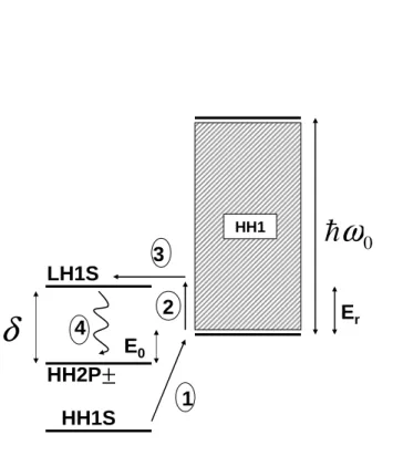
1 2 3 4
δ
E 0 0ω
Er LH1S HH2P±
HH1 HH1SFigure 2.2: Schematic 4-level operation of the THz laser. The operation involves three acceptor states LH1S, HH1S and HH2P± as well as the HH1 continuum (shaded region). The four major processes are also indicated. Process 1 indicates the field ionization of HH1S through the a barrier to reach HH1 minimum. The low-energy holes in HH1 are pumped toward resonant states by electric field in the Process 2. Process 3 represents resonant capture of continuum holes of energy Er to meta-stable LH1S. The radiative decay
by stimulated emission into the lower localized state HH2P± is denoted by Process 4.
hence are expected to give the strongest intensity of radiation among all pos-sible transitions. Besides, the acceptor 1s level attached to the heavy hole band edge is the very lowest state for holes in the system and is labeled by HH1S, which is shown below the HH2P± in Fig. 2.1. With precise control of Germanium compositions x and y in the QW structure, the heavy hole and light hole band edges as well as the localized acceptor levels can be adjusted to have the relative energies required for THz laser.
2.3
Mechanism for population inversion
Now we consider the pumping mechanism of the holes under an external electric field F (strength F ) perpendicular to the z direction, say x direc-tion. The physical picture is shown in Fig. 2.2. HH2P± is below LH1S and
minimum of HH1 by δ and E0 respectively. Note that in our problem δ
must be larger than E0 to have resonance between HH1 and LH1S. At zero
temperature all the holes stay in the low-lying HH1S state without field. When the external electric field is applied, some holes on HH1S are initially field-ionized then more holes are excited to HH1 through impact ionization and acquire more kinetic energy until occurrence of phonon scattering. The processes of field ionization and pumping of holes are denoted by Process 1 and 2 respectively in Fig. 2.2. Another channel for slowing down the holes in HH1 is the resonance capture by LH1S. The transition between heavy hole and light hole states, denoted by Process 3, is facilitated by the off-diagonal matrix element[11] of Luttinger-Kohn Hamiltonian to be discussed below. As the occupation of higher LH1S grows with increasing external field and the lower HH1S and HH2P± are gradually depleted by impact ionization, a population inversion is expected. Emission of THz photon, indicated by Process 4, will take place due to the radiative decay of holes from LH1S to HH2P±.
The resonance of the localized state and the continuum is achieved by raising the strain of the lattice so that the localized state is lifted to immerse within the continuum. In the previous works on QW RSL[12, 13] this ac-ceptor impurity is doped in the same layer as the continuous states, so E0
is simply the binding energy. Apparently in such case the strain splitting δ must exceed the binding energy, corresponding to a lower bound of photon energy. In this work we spatially separate the acceptor impurity and quan-tum well so the relative energy between the localized state and continuum has a much higher flexibility by adjusting the compositions x, y and the well width W . As a result no matter how small δ is we can always adjust the QW structure such that E0 < δ. However the only lower bound for the
emitted photon energy is the energy shift of the resonant state caused by the perturbation of the continuum as discussed previous Section. Hence our proposed structure is able to emit photon of energy less than the binding energy which is usually several tens of meV (12 THz in the case of Si ) and is expected to fulfill the needs of solid-state optical sources of several THz or even sub-THz range. Because the relative energies of the localized and continuous states are crucial to the laser operation, below we calculate the quantitative relations between the relevant levels in the QW structure and QW parameters like width W and Germanium compositions. Even though the acceptor levels are outside the central well, there is no difficulty for the holes in the central well to be resonantly captured by the acceptor as long as there is a overlap between the wavefunctions of the acceptor levels and HH1. In order for the above picture to be valid, it is important to choose an intermediate value for the distance between the dopants and the quantum
well. The distance should be neither so large relative to the acceptor Bohr radius that there is no overlap between the acceptor level and quantum well level nor so small that acceptor level itself becomes heavily influenced by the well.
Chapter 3
Theoretical modeling of
population inversion in a
continuum-trap system
3.1
Hybridization of acceptor impurity state
and valence band continuum
3.1.1
Subband and Impurity Wavefunctions
In this subsection we calculate the wavefunctions and energies of the rel-evant states. We first consider a perfect crystal. The wavefunctions for the heavy hole and light hole bands can be represented by the eigenfunc-tions of the Luttinger-Kohn Hamiltonian[15] HLK in the Bloch function
ba-sis {u3/2, u1/2, u−1/2, u−3/2}, which is the periodic sum of the atomic orbitals
with total angular momentum quantum number j = 3
2. The subscripts stand
for their z component jz of total angular momentum j. The column vector
Ψ formed by the envelope functions {ϕ3/2(r),ϕ1/2(r),ϕ−1/2(r),ϕ−3/2(r)} are
the eigenfunctions of HLK. The true wavefunction ψ(r) of the state is given
by ψ(r) = Στϕτ(r)uτ. The Luttinger-Kohn Hamiltonian can be written as
HLK = ¯h2 2m0 ˆa+ ˆb ˆc 0 ˆb† ˆa − 0 ˆc ˆc† 0 ˆa − −ˆb 0 ˆc† −ˆb† ˆa + jz = 3 2 jz = 12 jz = −12 jz = −3 2 , (3.1)
and the matrix elements are
k
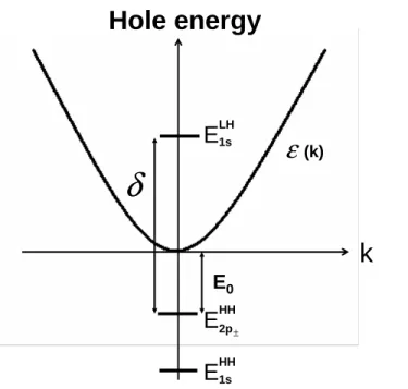
Hole energy
E
1s LHE
HH2p± E0δ
ε
(k)E
1s HHFigure 3.1: Spectrum of the diagonal part H0 of the full Hamiltonian H. The
acceptor states of interest and the continuous HH1 are shown. The binding energy for HH2P± and the emitted photon energy are denoted by E0 and δ respectively. Their values and corresponding variational Bohr radius is
ˆa−= −ˆkz(γ1+ 2γ)ˆkz− (γ1− γ)(ˆk2x+ ˆky2) , (3.3)
ˆb =√3(ˆkx− iˆky)(γˆkz+ ˆkzγ) , (3.4)
ˆc =√3γ(ˆkx− iˆky)2. (3.5) m0 is the free electron mass and ˆki = i∂x∂i, i = x , y, z are operators for the
envelope functions. γ1, γ2 and γ3 are material-dependent Luttinger
param-eters and γ = (2γ2 + 3γ3)/5. For crystals with translational invariance the
envelope functions are all proportional to plane waves eik·r and the above
operators turn into c-numbers. Diagonalization of the matrix gives the spec-trum E±(k) which possesses four-fold degeneracy at the band edge. The sign ± indicates that there are two branches, the heavy hole and light hole bands.
The spectrum E±(k) is given by
E±(k) = ¯h2 m0 " γ1 k2 2 ± q γ2 2k4+ 3(γ32− γ22)(k2xky2+ ky2kz2+ k2zkx2) # . (3.6)
When the perfect crystal is subject to a stress due to external strain or lattice mismatch the crystal symmetry is lowered, and the four-fold degen-eracy at the valence band edge is split into two two-fold degeneracies. If the strain is along the [001] axis, which is parallel to the z direction, this effect is to add a strain term Vst to the Hamiltonian.[16] It can be represented by
the diagonal matrix
Vst = ζ 0 0 0 0 −ζ 0 0 0 0 −ζ 0 0 0 0 ζ . (3.7)
The coincidence of heavy hole band and light hole band at band edge is split by the strain factor ζ which is proportional to external force and dependent on the direction of strain. In QW the strain results from the lattice mismatch between Si and SiGe alloy. In epitaxially grown SiGe QW structure on Si substrate, the lattice constant of the whole structure is fixed by the Si lattice constant. Because the natural lattice constant of SiGe alloy is different from Si, there must be a strain in the alloy to force the lattice constant to match Si. The relation between valence band splitting ζ due to strain and the Germanium composition t in Si1−tGet alloy was studied before.[17] The
expression in eV is ζ(t) = 0.01 + 0.2t − 1 4
√
0.0016 + 0.0074t + 0.24t2. In our
proposed QW structure the Germanium compositions vary in the z direction and the hence the strain factor ζ is a function of z .
For an acceptor in the stressed crystal we shall add the Coulomb potential
VI due to the charged center
VI(r) = vI(r)I =
1 4π²
e
rI , (3.8)
where ² is the dielectric constant. r is the distance from the acceptor. I represents the 4 × 4 identity matrix. In the high strain limit the off-diagonal coupling ˆb and ˆc can be considered as perturbations and HLK becomes
ap-proximately diagonal with two-fold degeneracy for heavy and light holes. The resultant localized states can also be divided into two subgroups like the band states.
After reviewing the bulk crystals we can extend the discussions to the states in QW structures shown in Fig. 2.1. Even without strain the valence band edge depends on the Germanium compositions,[18] described by Vb(z) = vb(z)I. For Si1−tGet alloy grown on Si, the valence band offset in eV can be
written as vb = 0.84t. The total band edge profile in Fig. 2.1 comes from
the sum of Vb(z) and Vst(z). The Luttinger parameters have different values
in different layers, hence they are functions of z. Homogeneity of those parameters is assumed within each Silicon-Germanium layer and their values are determined by linear interpolation between pure Si and pure Ge. The heavy hole and light hole subbands in the structure can be expressed by the total Hamiltonian H
H = HLK + Vb(z) + Vst(z) . (3.9)
Note that z=0 is at the center of well so there is a parity symmetry with respect to z → −z in this problem. Here we separate HLK into diagonal and
off-diagonal parts, labeled by H0
LK and HLK1 respectively. The wavefunctions
for HH1 emerge from eigenfunctions of diagonal parts H0 = H0
LK + Vb(z) + Vst(z) of the full Hamiltonian H. The off-diagonal heavy hole-light hole
mixing H1
LK will be considered later as a perturbation. The unperturbed
Schr¨odinger equation can be written as
H0Ψ = ²Ψ . (3.10)
We solve this to obtain HH1 envelope functions Ψ of the wavefunctions ψk
with eigenvalues ε(k). On the other hand, the localized states φLH
1s and φHH2p±
with respective eigenvalues ELH
1s and E2pHH± are eigenstates of Hamiltonian
H0
LK + VI(r) + [Vb(z) + Vst(z)]z=z±
0 . z
±
0 ≡ ±(W2 + d) denote the positions
of acceptors. The implicit assumption is that the Coulomb potentials VI
has little effect on the subband wavefunctions while the non-uniform strain is irrelevant to the localized state. The above approximations are justified
by the conditions that the distance between the dopant and quantum well boundary d as well as the thickness of outer Si1−xGex layers are both larger
than the acceptor Bohr radius. The equations turn out to be the typical one-dimensional potential well problem for the subband and hydrogen atom problem for the localized states. Energy spectrum for the relevant states are shown in Fig. 3.1. The explicit wavefunctions for HH1 can be expressed as
ψk(ρ, z) = 1 √ Ag(z)e ik·~ρu ±3/2, (3.11)
where the ± sign in the wavefunctions reflects the two-fold degeneracy guar-anteed by time-reversal symmetry in the absence of magnetic field and the envelope function g(z) have the even parity to yield the lowest energy of all subbands. A is the QW area. ~ρ = (x, y) is the in-plane coordinate. The acceptors wavefunction localized at z = z0± and ~ρ = 0 are of the forms
φLH 1s (~ρ, z) = ϕ1s h ~ρ, z − z± 0 i u±1/2, (3.12) φHH 2p±(~ρ, z) = ϕ2p± h ~ρ, z − z± 0 i u±3/2, (3.13)
where ± stands for z > 0 and z < 0 respectively. We use hydrogenic trial functions ϕ1s(~ρ, z) = √1 πa2bexp − s ρ2 a2 + z2 b2 , (3.14) ϕ2p±(~ρ, z) = 1 2πa4bρe iφexp − s ρ2 a2 + z2 b2 . (3.15)
a (in-plane Bohr radius) and b (out-of plane Bohr radius) are variation
pa-rameters for minimizing their energy and φ is the polar angle in the xy plane. ρ is the modulus |~ρ|. Variational calculations are performed to ob-tain the acceptor level splitting δ and the difference E0 between HH2P± and
HH1 minimum. Variational calculations are performed to obtain the accep-tor level binding energy. The resultant binding energies and the variational Bohr radius of the levels of interest are shown in Table I.
Next we consider the corrections to the impurity states resulting from the QW confinement potential as well as the off-diagonal couplings with the HH1 continuum. Such corrections are necessary for having a more precise prediction on the emitted photon energy. Here we focus on the corrections to the binding energy of LH1S, which is resonant with the continuum. Note that the binding energy is relative to the barrier, not the quantum well continuum.
The expressions for the corrections ∆E1s are given below and the details of
derivation are presented in Appendix 4.1.
∆E1s= ∆ + P A (2π)2 Z dk |αk| 2 E1s− εk . (3.16) ∆ is the correction due to the confinement potential while the integral due to the coupling with the continuum. P stands for the Cauchy principle value integration. αk and ∆ are given by
αk = hϕ1s|ˆc|ψki , (3.17)
∆ = hϕ1s| [vC(z) − vC(z0)] |ϕ1si . (3.18)
Note that only the off-diagonal elements involving kx and ky are considered
because the resonance requires a large in-plane momentum. The confinement potential vC is the diagonal element of Vb+ Vst belonging to light hole states.
Correction due to the confinement potential ∆ is negligible in the present case because very little portion of the impurity wavefunction for the impurity falls on the QW region and the confinement potential is small compared to the impurity binding energy. In fact our calculation shows this correction on
E1s is less than 0.1 %. However this effect for the case of smaller binding
energy is important such as the shallow donors located in the barrier near the quantum well.[19] The second term resembles the formula for second order perturbation. Even though still only about 10 % of E1s, it provides significant
corrections in case of the small emitted photon energy. The smallness of the corrections is reasonable since the light hole localized states and the heavy hole continuum have small overlap and they can couple to each other only though the off-diagonal elements of HLK which is treated as perturbation in
the high-strain limit.[11] The QW continuum and the HH2P± are assumed to be unaffected by the perturbation.
3.1.2
Resonant transition
The hybridization of the localized LH1S and the HH1 continuum via the off-diagonal perturbation H1
LK leads to a new set of resonant states {ΨE}
labeled by its complex energy E + iΓE
2 . The imaginary part is given by
ΓE 2 = π A (2π)2 Z dkδ(E − εk)|αk|2. (3.19)
The nonzero imaginary energy ΓE here represents that ΨEis a quasi-stationary
state. More precisely speaking the HH1 holes of momentum k can be cap-tured by LH1S with the transition rate Wres
0 0.5 1 1.5 2 2.5 3 3.5 4 0 0.2 0.4 0.6 0.8 1 1.2 1.4 1.6 1.8 d1 d2 d3 Resonance energy E r (meV) Resonant width Γ (meV) b1 b2 b3 d=6 nm d=9 nm a=5.4 nm a=8.1 nm
Figure 3.2: The energy width Γ of the resonant state is shown as a function of the resonant state energy Er measured from HH1 minimum. Symbol
curves correspond to various in-plane Bohr radius a of LH1S orbital with fixed d = 6 nm. Dash and dot lines correspond to various distance d between the acceptor and boundary of the central well with a = 2.7 nm.
transition rate and the time interval are determined in a self-consistent man-ner, that is Wkres = 2 ¯h|αk| 2 Γ/2 [ε(k) − E1s]2+ Γ2/4 , (3.20) Γ ¯h = X k Wres k . (3.21)
The center of the Lorentzian corresponds to E1s because the resonant state
ΨE1s contains the maximum component of the localized LH1S. For simplicity
we regard the unknown Γ in Eq. (3.20) as close to zero and the Lorentzian is reduced to a delta function. So long as the resultant Γ from Eq. (3.21) is small compared to the resonance energy Er ≡ E1s− ε(k = 0) (see Fig. 2.2,
3.1) of LH1S, this method is self-consistent to obtain Γ.
Next work out Γ in the small Γ limit. In other words the resonant tran-sition rate Wres
k can be given simply by the Fermi-Golden rule, Wres k = 2π ¯h |αk| 2δ [ε(k) − E 1s] . (3.22)
calculate the overlap integral hϕ1s|ψki. Assuming the main contribution to
this integral comes from the region in the barrier, i.e. |z| > W
2 , we arrive at hϕ1s|ψki = 1 √ A 1 √ πa2b Z dz g(z) Z
dxdy ei~k·~ρexp − s ρ2 a2 + z2 b2 (3.23) = ℵ s 16πab2 A 1 η2 ( e−ηd b 1 κb − η " κb − 2η η(κb − η) + d b # + e−κd " (2η − κb) η(κb − η)2 + (2η + κb) η(κb + η)2 #) .
The dimensionless quantity η ≡ √1 + a2k2 is introduced. ℵ is to normalize
the envelope function g(z) as R ℵ2|g(z)|2dz = 1. κ is the decay constant of g(z) in the barriers.
Γ as a function of resonance energy Er is plotted in Fig. 3.2 for various
acceptor in-plane Bohr radius a and separation d. The effect of coupling with the continuum can be investigated through Γ. For distance d much larger than the Bohr radius, the coupling is diminished due to decreasing overlap between the impurity state and the continuum. In such case the formation of resonant state is impossible. However the dependence of the coupling on the Bohr radius is determined by two competing factors. Namely in the z direction the envelope function g(z) of continuum has larger overlap with localized impurity state of larger Bohr radius, while in the xy plane the continuum of higher kinetic energy can only be coupled to the impurity state of smaller Bohr radius because such localized state has larger Fourier momentum components. For larger Bohr radius, it is shown in Fig. 3.2 that Γ is larger at lower Er while it is smaller at higher Er.
3.2
Carrier kinematics in the steady electric
field
So far there is no comprehensive theoretical model for the non-equilibrium behavior of acceptor levels interacting with a subband in QW. In order to make quantitative predictions of the conditions for hole population inversion, below we construct a model which takes into account of all the relevant physical processes for such system.
3.2.1
Hole Statistics at equilibrium
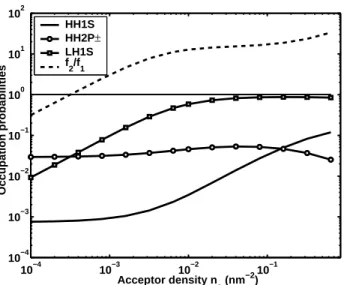
The occupation probabilities of LH1S, HH2P±, HH1S and HH1 states are indicated by f1, f2, fg and fk respectively. In thermal equilibrium the
f2/f1 = exp(−βδ). β is the inverse of the product of Boltzmann constant kB and temperature T . Moreover at equilibrium the hole densities are de-termined by assigning each level with its Boltzmann weighting. Note the all the holes are provided by the lowest localized level and hence we have the following normalization of total holes.
nafg + naf1+ 1 A X k fk+ naf2 = na. (3.24)
When the electric field is turned on holes acquire kinetic energy from the external field and the distribution of holes deviates from Boltzmann distri-bution. In order to give a quantitative account of how the non-equilibrium populations depend on parameters (e.g. field strength F , temperature T , and acceptor density na), we need to study the microscopic kinetics governing the
transitions among the states.
3.2.2
Boltzmann Kinematic Equation
The strategy for obtaining the non-equilibrium populations is as follows. First we neglect the low-lying HH2P± and HH1S temporarily and solve the kinetics of the subsystem containing HH1 and LH1S in order to obtain the relation between f2 and fk, with considerations of phonon scattering within
HH1 and the resonant transition between the continuous HH1 and the local-ized LH1S. This is justified because the resonant scattering is much faster than the decay through spontaneous emission from LH1S to HH2P±.[10] Afterwards the occupation probability f1 of HH2P± is determined by the
its balance with non-equilibrium subband distribution fk through impact
ionization, thermal recombination, and their inverse processes Auger recom-bination and thermal excitation. Detailed calculations are given below.
For a given number of holes in the subsystem containing HH1 and LH1S, the non-equilibrium distribution fk in HH1 and occupation of LH1S f2 are
studied by solving the Boltzmann kinetic equation numerically for various electric fields and acceptor densities. In the subsystem the holes in HH1 acquire kinetic energy from the constant electric field F applied along the x axis. For moderate electric field and low temperature, it is adequate to adopt the concept of streaming motion[22] in which the only significant scattering is due to optical phonon (energy ¯hω0). This is implemented by introducing
a particle drain in momentum space such that once a specific hole drifts with velocity eF/¯h through the energy surface ε = ¯hω0 (denoted by Π) in
the momentum space, the hole will experience a optical phonon scattering and simultaneously reemerge as a hole of energy less than ²0.[10, 11] Hence fk = 0 for ε(k) ≥ ¯hω0. The energy ²0 is determined by the requirement
that in the presence of constant electric field F the probability for a hole being able to drift beyond the constant energy surface ε = ¯hω0+ ²0 without
emitting one optical phonon is negligibly small. The quantity ²0 is equal to
the product of external force eF , carrier velocity √2m∗¯hω
0/¯h and inverse
of the average optical phonon emitting rate νA. m∗ stands for the effective
mass. Note that the energy-independent optical phonon emitting rate is due to the constant density of states in two dimension. Therefore the excess energy can be expressed as
²0 = eF νA s 2¯hω0 m∗ . (3.25)
The reemerging holes can be modeled as a particle source[10, 11]
S(k, t) = e ¯ h[ R Πfk(t)F · dS] [R Θ(²0− ε(k0))d2k0] Θ(²0− ε(k)) , (3.26)
where Θ is the step function. The meaning of the above expression is that the holes reemerging rate is uniform for energy within ²0, and the total
reemer-gence rate must match the collection of the outward carrier flux eF ¯
h fkpassing
through the surface Π in the momentum space.
In order to properly account for the temperature effects, we include the acoustic phonon scattering. The acoustic phonon scattering rate Wacu
k,k0 is of the form[23] Wk,kacu0 = 2πΞ2q2 %ωqW A (nq+ 1 2 ∓ 1 2)δ [ε(k 0) − ε(k) ∓ ¯hω q] , (3.27)
where % is the mass density of solid lattice and Ξ is the lattice deformation potential. The acoustic phonon involved in the transition has wave number q = k0−k and its dispersion is given by ωq = cq where c is the sound velocity
in the solid. Emission and absorption of phonon in the processes correspond to + and − respectively. The product W A represents the QW volume.
We assume homogeneity in the x and y directions so that the distribution are function of variables kx and ky only. The set of kinetic equations can be
written as ∂fk ∂t + eF ¯h · ∂fk ∂k = Sk− Dk+ C1[fk, f2] , (3.28) ∂f2 ∂t = C2[fk, f2] . (3.29)
Ci[fk, f2] , i = 1, 2 represent the collision terms for the acoustic phonon and
resonant scattering. They are functionals of the the distribution functions. The explicit expression for the collision terms are
C1[fk, f2] = naA {Wkres(f2− fk)} + X k0 {Wacu k0kfk0− Wkkacu0fk} , (3.30) C2[fk, f2] = X k Wres k (fk− f2) . (3.31)
The kinetic equations Eq. (3.28) and Eq. (3.29) are solved numerically by starting with the equilibrium distribution and then integrating forward in time until a steady state is reached. Note that the sum of densities naf2+
1 A
P
kfk is a conserved quantity in the time evolution, guaranteed by
cance-lation of collision terms and the boundary conditions at surface Π. In this way not only the steady state but also the transient of the system can be modeled. The occupations of LH1S f2 and the HH1 fk are obtained up to an
arbitrary total number of holes in the subsystem. In particular the relation between f2and fkat steady state can be readily seen by setting the left hand
side of Eq. (3.29) equal to zero
f2 = P kWkresfk P kWkres = Z dεδ [ε(k) − Er] fk. (3.32)
Now we consider the special case with no electric field. The subsystem is in thermal equilibrium. The occupations of HH1 and LH1S obey the Boltz-mann statistics guaranteed by the presence of delta function in the expression for resonant scattering as well as the fact that the scattering between HH1 states k and k0 due to acoustic phonon emission and absorption satisfies the
relations Wacu k0k Wacu kk0 = 1 + nq nq = exp {−β [ε(k0) − ε(k)]} . (3.33)
ε(k0) > ε(k) is assumed without loss of generality and q is the wavevector of
the phonon involved in the process. Therefore in equilibrium f2 is given by
f2 = N/A 1 A P ke−βε(k)+ nae−βEr e−βEr , (3.34)
where N represents the total number of holes in the subsystem.
In order to describe the effect of the electric field on the distribution, we define a dimensionless parameter λ(F, T ) by
λ(F, T ) ≡ 1 A P kfk naf2+ 1 A P kfk = ns n2+ ns . (3.35)
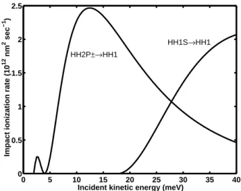
0 5 10 15 20 25 30 35 40 0 0.5 1 1.5 2 2.5
Incident kinetic energy (meV)
Impact ionization rate (10
12 nm 2 sec −1 ) HH2P±→HH1 HH1S→HH1
Figure 3.3: Impact ionization rates wip as functions of kinetic energy ε of
incident subband hole for HH1S to HH1 and HH2P± to HH1 are respectively shown.
λ(F, T ) is the fraction of holes in HH1 for the subsystem. For low
temper-ature at equilibrium virtually all holes stay near the HH1 minimum so λ is close to unity. In the presence of the electric field the population of LH1S increases as a consequence of Eq. (3.32), since holes in HH1 acquire kinetic energy from field so the non-equilibrium distribution fk has larger value at ε(k) = Er. Therefore for given na, λ(F, T ) is expected to decrease as electric
field increases. Increase of acceptor density na also raise f2 because the
dis-tribution in HH1 becomes more concentrated on ε(k) ≤ Er. This is because
the stronger resonance scattering inhibits the holes to acquire energy higher than the resonance energy Er.
3.2.3
Impact Ionization and thermal recombination rates
Next we turn to the interactions between HH1 and low-lying localized states including HH1S and HH2P±. The interactions are dominated by impact ionization and the thermal recombination as well as their inverse processes. In impact ionization process one energetic hole in HH1 with momentum k scatters with one hole in the low-lying localized states φb in the barrier
through the Coulomb interaction such that they both come out as free holes in HH1. The transition rate is given by
wip(k) = 2π ¯h X k1,k2 ¯ ¯ ¯ ¯ ¯ * k1, k2 ¯ ¯ ¯ ¯ ¯ e2 r ¯ ¯ ¯ ¯ ¯k, b +¯¯ ¯ ¯ ¯ 2 δ [ε(k) − Eb− ε(k1) − ε(k2)] , (3.36)
where r is the separation between the incident hole and localized hole. The summation is over all the final two particle Bloch states (k1, k2). The first
task is to evaluate the scattering matrix element hk1, k2|e 2
r|k, bi.
Substitut-ing the explicit expressions for those localized wavefunctions and Coulomb potential into the scattering matrix element, it becomes
Z d3r1d3r2 1 √ Ae −ik1·~ρ1f∗(z 1) 1 √ Ae −ik2·~ρ2f∗(z 2)V (|r1− r2|) 1 √ Ae ik1·~ρ1f (z1)φ b(r2), (3.37) where the dummy coordinates ri = (~ρi, zi), i = 1, 2 are to be integrated out
to obtain a impact ionization rate as a function of the momentum k of the incident hole. The integral is complicated by the entanglement of dummy variables r1 and r2 but it can be eased by replacing the Coulomb interaction
with its representation in Fourier expansions 1 4π² e2 |r1− r2| = e 2 ² Z d3q (2π)3 1 q2e iq·r1e−iq·r2 . (3.38)
Similar to Eq. (3.24) the overlap between the HH1 and LH1S, the major contributions to the matrix element come from |z| > W
2 . After some algebra
the scattering amplitude M arrives at the expression
M (k; k1, k2) = * k1, k2 ¯ ¯ ¯ ¯ ¯ e2 r ¯ ¯ ¯ ¯ ¯k, b + = 1 A3/2 e2 ² Z dq ⊥ 2π 1 q2 k+ q⊥2 Z dz1|f (z1)|2eiq⊥z1 R dz2f∗(z2)I(z2, q0)e−iq⊥z2. (3.39) qk = |k − k1| and the expression for I(z) is given by
I(z, q0) = s 4πa2 b Z ∞ 0 dρh(ρ)exp − Ã ρ2+ (z − z ± 0)2 b2 !1 2 , (3.40)
where the function h(ρ) is ρJ0(aq0ρ) for the case of HH1S as initial state
and is q1
Bessel functions. q0 = |k − k
1 − k2| and χ = q
1 + a2q02. The upper script ± is for z > 0 and z < 0 respectively. Note that I(z, q0) decreases with the
momentum transfer q0 as a consequence of localization of the initial acceptor
state. The scattering amplitude is expected to decrease rapidly when the momentum transfer q0 is larger than the inverse of the Bohr radius a of the
localized orbital. Hence we simplify the expression Eq. (3.36) as
wip(k) = 2π ¯h |M| 2 X k1,k2 Θ(1 a − |k − k1− k2|) × δ [ε(k) − E0− ε(k1) − ε(k2)] (3.41) = 2π ¯h |M| 2σ(k) .
M stands for the maximum scattering amplitude which occurs when k1 = k2,
and the angel between k and k1 is equal to that between k and k2. The
summation in the above expression gives the effective phase space volume
σ(k) available for this scattering process given that the incident momentum
is k. Carrying out k1 and k2 integral one obtains
σ(k) = A2 Z d2k 1 (2π)2 d2k 2 (2π)2Θ( 1 a − |k − k1− k2|) × δ [ε(k) − E0− ε(k1) − ε(k2)] (3.42) = Ã A (2π)2 !2Z d2u 2 d 2vΘ(1 a − u)δ ( ¯h2 2m 1 2 ³ |u + k|2+ v2´− [ε(k) − E 0] ) = A 2 2π m ¯h2 Z d2uΘ(1 a − u)Θ " − ¯h 2 4m|u + k| 2 + (ε(k) − E 0) # ,
where the phase space dummy variables (k1, k2) was transformed into the new coordinates (u, v) = (k1 + k2, k1 − k2) with corresponding Jacobian
equals one half. After integrating out the variable v the evaluation of σ(k) can be obtained through counting the overlapping area of one circle centered at origin with radius 1/a and another circle centered at −k on the x-axis with radius
√
4m[ε(k)−E0] ¯
h . The resultant rate wip is plotted in Fig. 3.3 as
a function of kinetic energy ¯h2k2
2m∗. The reverse process of impact ionization
is Auger recombination, in which two HH1 holes collide and result in one localized hole and one HH1 hole with higher kinetic energy. Auger process must be taken into account as well.
The holes impact-ionized to the HH1 can go back to the low-lying local-ized states by acoustic phonon emission, i.e. the thermal recombination. The thermal recombination rate is given by[24]
wtr(k) = 210πc l0 E4 0m∗c2 [ε(k) + E0]5 a3¯¯¯g(z0±)¯¯¯2(Nq+ 1) , (3.43)
where c is the sound velocity. Nq is the number of phonon involved in the
scattering and q is the wave vector of the phonon satisfying conservation of energy given by q = [ε(k) + E0] /¯hc. l0 is the characteristic length for
acoustic phonon scattering
l0 =
π¯h4%
2m∗3Ξ2 , (3.44)
where % and Ξ are mass density of the lattice and deformation potential as mentioned previously. The reverse process of the thermal recombination is the thermal excitation of holes in the low-lying localized states by acoustic phonon absorption.
Between the two localized levels, HH1S and HH2P±, the thermal cap-ture/generation rates ta/e are given by
ta/e= 210 c l0 mc2 ∆² (Nq+ 1 2∓ 1 2) . (3.45) ∆² denotes the energy difference between the localized levels. The subscripts
a and e indicate that these processes are accompanied by phonon absorption
and phonon emission respectively.
3.2.4
Hole population in subband and lower localized
acceptor states
From Section 3.2.2 we are able to deal with the non-equilibrium occupations
fkand f2 with normalization up to an arbitrary total number of holes. Using
the impact ionization and phonon emission rates we are now able to deal with the occupations in the subsystem consisting of lower localized levels and HH1. To be precise, we adopt the normalization given by Eq. (3.24) where the total hole density of subsystem consisting of LH1S and HH1 is equal to the vacancy density in HH2P± and HH1S. Since the occupation probability f2 is completely determined from fk, it is convenient to write the
density of HH1 holes ns as
ns = ns
ns+ naf2(ns+ naf2) = λ(F, T )na(1 − f1− fg) , (3.46)
and the hole density of LH1S as
100 101 10 20 30 40 50 60 70
Hole energy ε (meV)
Subband hole distribution f(
ε ) k p 2/2 π 2n s E r n a=1.0x10 −4 nm−2 n a=6.4x10 −3 nm−2 n a=1.9x10 −1 nm−2
Figure 3.4: Normalized subband hole distribution ˜f (ε) versus hole energy ε
for electric field strength of F = 1000 V/cm and T = 1 K. The vertical line denotes the resonance energy Er. The distribution concentrates more in the ε < Er region as acceptor density na increases.
The dimensionless parameter λ(F, T ), given by Eq. (3.35), has values between zero and unity.
Once f1 and fg are known, f2 can be determined from Eq. (3.47). f1
and fg can be calculated from the kinetics between HH1 and the low-lying
localized states. Impact ionization and thermal excitation processes cause the upward transitions while Auger recombination and thermal recombination processes cause the downward transitions. The respective downward Auger recombination rates from HH1 to HH2P± and HH1S are rar
2p = A2p(T )n2s(1 − f1) and r1sar = A1s(T )n2s(1 − fg), where the coefficients A’s are
temperature-and acceptor density-dependent for the Auger recombination temperature-and the factors (1-f1,g) account for the constraint that the process is forbidden when the lower
acceptor state is filled with a hole. Note that holes in HH1 are not required to have threshold kinetic energy for the recombination process to take place, so we assume the coefficients A’s have a negligible field dependence. The holes occupied the continuum can drop to the lower localized states, HH1S and HH2P±, by thermal recombination. In our case HH2P± is below the HH1 minimum by 2 meV, which is much smaller than the gap between HH1 and HH1S, 16 meV; here we neglect the latter recombination process since the rate is inversely proportional to the gap. This downward rate from HH1 to HH2P± is proportional to the hole density in HH1 and can be written as rtr
2p= C(F, T )ns. The coefficient C(F, T ), dependent on field and temperature, is
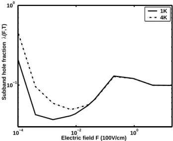
10−4 10−2 100 10−1
100
Electric field F (100V/cm)
Subband hole fraction
λ
(F,T)
1K 4K
Figure 3.5: The subband hole fractions λ(F, T ) as a function of electric field
F for T = 1 K (solid) and T = 4 K (dashed) are shown. The coincidence
for different temperatures at higher electric fields suggests that kBT becomes
irrelevant compared with the scale of Er and optical phonon energy ¯hω0.
taken as the average of Eq. (3.43) with respect to fk
C(F, T ) = P kwtr(ε(k)) fk P kfk . (3.48)
We now consider upward transitions. The impact ionization rates for the re-spective processes, HH1S to HH1 and HH2P± to HH1, are of the expressions,
r1sip = B(F, T )nsfg and r2pip = B(F, T )nsf1. Note that the factors f1 and fg
in the expressions account for the requirement of occupied initial localized acceptor state. The coefficients Bi(F, T ) can be written as the average
Bi(F, T ) = P kwipi (ε(k)) fk P kfk . (3.49)
The subscript of wipi in Eq. (3.49) stands for different rates resulting from dif-ferent initial localized states in the difdif-ferent collision processes in the present case. There exists a threshold of kinetic energy for the hole in HH1 for impact ionization and consequently the coefficient B for low field and low temperature is negligibly small. Besides the upward transition caused by the inelastic collision, holes occupying the lower localized states can also be excited to the continuum through phonon emission. Here we also neglect
the direct excitation of HH1S holes to HH1 because it requires absorption of phonon of much greater energy. Therefore we are left with the thermal exci-tation from HH2P± to HH1, and the rate can be expressed as rte = D(T )n
1.
The phonon absorption coefficient D(T ) is determined by detailed balance with rtr at thermal equilibrium.
Since we have to consider two lower localized states in the kinetic problem, we are left with the transition between HH1S and HH2P±. For simplicity we only consider the thermal excitation and recombination. The upward and downward transition among the two levels are given by tang and ten1.
With all the necessary transitions at hand it is ready to write down the kinetic equations for the populations n1 and ng of the two localized states.
Substitute all the formula into the relation we have
dn1 dt − tang+ ten1 = r ar 2p− r2pip + rtr− rte (3.50) = A2pn2s(1 − f1) − B2pnsf1+ Cns− Dn1. dng dt + tang− ten1 = r ar 1s − r1sip = A1sn2s(1 − fg) − B1snsfg.
Now we are left with the determination of the coefficients A1s, A2p and D which are assumed to be independent of the electric field. Since the
oc-cupations obtained from the rate equation must be restored to the thermal equilibrium when the electric field is set to zero, the requirement of detailed balance at zero field give A1s, A2p and D using B1s, B2p and C
A2p(T ) ³ n0 s ´2 (1 − f0 1) = B2p(F = 0, T )n0sf10, A1s(T )³n0s´2(1 − fg0) = B1s(F = 0, T )n0sfg0, D(T )n01 = C(F = 0, T )n0s. (3.51) Note that the zeros as upper scripts in fg, f1, n1 and ns stand for the
equi-librium values.
3.3
Population inversion in quantum well
res-onant state laser
For given F and T , Eq. (3.50) can be solved to give fg and f1. Then they
population inversion. Putting everything together we are now able to ob-tain the non-equilibrium distribution of holes in all the levels under electric field pumping. For the subsystem containing LH1S and HH1, the normal-ized subband distribution ˜f (ε) ≡ f (ε) k2p
(2π)2ns versus hole kinetic energy for
different acceptor densities is shown in Fig. 3.4 with applied electric field 1 KV/cm. kp stands for the hole momentum corresponding to kinetic energy
of one optical phonon energy ¯hω0=40 meV and the integration R
|k|<kpf (ε)dε˜
gives unity. For lower acceptor densities na holes in HH1 are more likely to
be pumped to acquire energy exceeding resonance energy Er. This results
in lower occupation below Er. Higher acceptor densities na lead to higher
occupation probability at Er, i.e. larger ˜f (Er). This phenomena results from
strong resonant scattering for higher acceptor densities. From Eq. (3.32) the occupation f2 of LH1S is consequently enhanced with increasing acceptor
density. In other words for same hole density in HH1, higher acceptor den-sities na lead to higher LH1S occupation probabilities f2. Therefore higher na is advantageous for building population inversion. The effect of electric
field is shown in Fig. 3.5 by plotting the subband hole fraction λ. At low field, the occupation of LH1S compared to that of HH1 is suppressed by the Boltzmann factor and λ is near unity. As the field is turned on (between 10−2 and 10−1 V/cm), holes acquire kinetic energy by field pumping. Hence
more holes accumulate in LH1S through resonant capture of holes in HH1 with kinetic energy ε(k) = Er. As the field further increases, the fraction λ starts to increase because the field pumping overwhelms resonant capture
and acoustic phonon scattering. In that case large fraction of holes in HH1 acquire kinetic energy larger than Er. The temperature effect diminishes
in this regime as shown by the coincidence of the two curves in Fig. 3.5. Eventually the growth of λ in the high field regime saturates when optical phonon scattering sets in.
Next we consider the subsystem consisting of HH1 and the lower localized states. At low temperature and equilibrium, most of the holes are bound by the acceptors and occupy the lowest HH1S. There are very few holes on HH1 and even fewer holes with enough kinetic energy to inelastically collide with the localized holes. Therefore the process of impact ionization is negligible, and the so is the Auger recombination because in such dilute case the average distance between the free holes is so large that the probability of collision is extremely small. Hence the populations of these levels are dominated by the thermal processes and the statistics obey the Boltzmann distribution. When the electric field is turned on, holes can acquire more kinetic energy and the impact ionization of the low-lying localized state is possible through the inelastic collisions with energetic holes. The subsequent distribution of
0 0.5 1 1.5 2 10−10
10−5 100
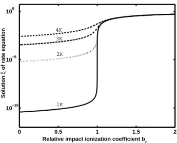
Relative impact ionization coefficient b c Solution ξ of rate equation 1K 2K 3K 4K
Figure 3.6: The solution ξ of equation Eq. (3.52) at low field and low tem-perature is shown as a function of the relative impact ionization coefficient
bc. The abrupt jump around bc = 1 is due to the depletion of the lower
localized levels by impact ionization.
holes are balanced by those upward and downward transitions, as illustrated in Eq. (3.50). In order to have a quantitative understanding of how electric field change the steady-state distribution of holes as the impact ionization rates increase, it is easier to consider the subsystem as HH1 and one single localized state, which is below HH1 minimum by eg. The rate equation can
be written in a similar manner, that is
˜
Anaλ2ξ3+ ˜Bλξ2+ ( ˜C − ˜B +
˜
D
λ)λξ − D = 0 . (3.52)
The variable ξ = 1 − ˜f and ˜f stands for the population in the localized
state. The capital letters with tildes represent the effective coefficients for the corresponding processes. Now we first focus on the limit of low temperature and low field. In such case the occupation of lower localized levels is close to unity (ξ ¿ 1) and the impact ionization coefficient ˜B is nearly zero. So it is
a good approximation to neglect the term of highest power in ξ in the rate equation Eq. (3.52). The solution is given by
ξ = ( ˜B − ˜C)λ + q
( ˜B − ˜C)2λ2+ 4λ ˜B ˜D
2λ ˜B , (3.53)
![Figure 1.2: The valence band potential for a quantum cascade laser in Si/SiGe superlattice[1]](https://thumb-ap.123doks.com/thumbv2/9libinfo/8526394.186880/10.918.279.618.308.662/figure-valence-potential-quantum-cascade-laser-sige-superlattice.webp)
![Figure 1.3: A schematic of the operation for emission of THz radiation based on the resonant state in strained p-Ge[11]](https://thumb-ap.123doks.com/thumbv2/9libinfo/8526394.186880/12.918.266.615.395.712/figure-schematic-operation-emission-radiation-based-resonant-strained.webp)