References
1 WATERHOUSE. R.B.: 'Small microstrip patch antenna', Electron. Lett., 1995, 31, pp. 604605
2 R O W L E Y . J.T., and WATERHOUSE. R.B.: 'Performance of shorted microstrip patch antennas for mobile communications handsets at 1800MHz', IEEE Trans. Antennas Propug., (to appear)
3 WATERHOUSE, R.B., R O W L E Y , J.T., and JOYNER. K.H.: 'Stacked shorted patch', Electron. Lett.. 1998, 34, pp. 612-614
4 TARGONSKI. s.D., WATERHOUSE, R B., and POZAR, D.M.: 'Design of
wideband aperturestacked patch microstrip antennas', IEEE Trans. Antennas Propug., 1998, AP-46, pp. 1245-1251
5 Ensemble 5.1, Ansoft, 1998
Microstrip leaky-wave antenna fed by
short-
end CPW-to-slot transition
Tai-Lee Chen and Yu-De Lin
Single and dual-beam microstrip leaky-wave antennas fed by a short-end coplanar waveguide (CPW)-to-slot transition are presented. The radiation bands of the antennas are deduced from the leaky-wave propagation characteristics of the microstrip line first higher order leaky mode. The measured reflection coeflicients of the radiation band confirm the predicted leaky band and the measured radiation paffems exhibit the frequency-scanning feature of the leaky-wave antenna. The short-end CPW-to-slot transition feeding method simplifies the circuit layout and is more suitable for different band design than the CPW-fed microstrip first higher order leaky-wave antennas presented in the literature.
Introduction: The microstrip line leaky-wave theory and applica-
tions have attracted wide interests and discussions since the exper- iment proposed by Menzel [l]. The leaky-wave antenna based on the higher order modes of planar transmission lines possesses the advantages of wider bandwidth, frequency scanning, relaxed requrement of tolerance, etc. [2]. Besides being fed by an unsym- metrical microstrip line in [l], several methods to excite the micro- strip line first higher order leaky mode have been developed recently [3 ~ 71. The efficiency of feeding structures using a slot, coupled slots, and coplanar strips were investigated in [3]. The aperture-coupled method that exhibits the broadband characteris- tic of the leaky-wave antenna with lower-dielectric constant sub- strate is shown in [4, 51. For coplanar waveguide (CPW)-based feeding structures, a CPW-to-slot transition with a quarter-wave-
length CPW open stub [6] and a direct open-end CPW [7] were used to excite the leaky-wave antenna. The CPW quarter-wave- length open stub takes up some area of the circuit layout and may lead to unwanted resonance, while the direct open-end CPPJ may be difficult to adjust to the desired frequency band. Here, we present a slot-fed microstrip first higher order leaky-wave antenna with short-end CPW transition, which has none of the above- mentioned shortcomings.
Y
grou
plane a
Antennu design: The configuration of the short-end CPW-to-slot
transiticn fed leaky-wave antennas are shown in Fig. I . Fig. la shows the single squint beam design and Fig. l h shows the dual- beam design. Short-end CPW-to-slot transition is arranged on the ground plane of the microstrip. The width of the leaky-wave microstrip antenna is determined by the desired frequency band in which the space-leaky wave occurred. The leaky region, as shown in Fig. 2, is determined by the normalised phase (p/k,,) and attenu-
ation
(dk,,)
constants of the microstrip first higher order leaky mode, which can be obtained by the spectral domain integral equation method as in [8], where k,, is the free space propagationconstant. The space-wave leaky region is about 9.7 to 10.5GHz with i v = 4.1" and substrate thickness h = 0.635" for sub- strate dielectric constant E, = 10.2.
m (I,
-
7 7 9 0 9.5 10.0 10.5 11.0 frequency,GHzFig. 2 Nornialised phase constant p/k,, and attenuation constant Wk,, of
first higher order leaky mode of inicrostrip line and rwasured return
1or.r of mntennas in Fig I
m
SBA DBA - - - - - -E, = 10 2, 1v = 4.1. / I = 0.635 L 90" 270" - C € w - Fig. 3 Wearurrd H-plane radiation pattern, E , on Y-2 plane at 9 9 anti 10 2GEIz for SBA~ 99GHz 10 2GHz - - -
'
7
7
1
I 1 I L I A b @ Fig. 1 Microstrip leaky-wave antennas f e d by short-end CP W-to-slot transitiona Single-beam antenna
L = 80mm, = 4.1". k. = 6.4mm3 It = 1 . h " 1s = 4.61" strip of CPW = 1.32". gap of CPW = 0.4 mm, slot width = 0.2mm, E, =
10.2, h = 0.635mm
b Dual-beam antenna
le = 6.9
Using higher-dielectric constant substrate leads to a narrower leaky band when the centre frequency of the design is futed (result- ing in a narrower strip width). The spatial scanning property, with the elevation angle
e
cos I p/ku, will not be affected significantly.This can be seen by estimating the cutoff frequency of the waveguide model with different dielectric constant substrates and verified by our case compared with the leaky band in [4]. The
consideration of a narrower leaky bandwidth antenna is because some of the connected active elements, such as the voltage-con- trolled oscillator (VCO), do not usually span a wide frequency range. The choice of a thinner substrate for the same frequency design (with wider strip width resulted to compensate the fringing effect) will result in a narrower beamwidth because its cdk,, is
smaller and therefore the far field obtained by the Fourier trans- form has a narrower beamwidth. Here, we use c2cd to roughly
estimate that the survival power will be less than 5% at I0.2GHz
at the end of the leaky-wave antenna.
The overlap (coupling length IC in Fig. 1) of the slot and the leaky-wave microstrip is chosen to be shorter than &I4 for the desired frequency band to prevent the conflict of fields on the slot and the leaky microstrip line, where h, is the guided wavelength of
the microstrip line first higher order leaky mode. A short-end CPW to slot line transition was used to match the input 50Q CPW so as to connect easily with other circuits based on the CPW. The other slot outside the microstrip of the single-beam antenna (SBA) in Fig. l a serves as a part of the matching circuit.
2
90"
,loo\
/,,,
270'
om4
Fig. 4 Measured H-plane radiation patterns E, on .Y-: plune ut 9.9 and IO.2GHz for DBA
_ _ - _ I0.2GHz
___ 9.9GHz
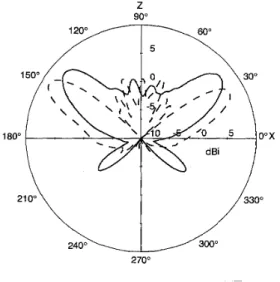
Experimental results: The measured return losses of both antennas depicted in Fig. 1 are also shown in Fig. 2. Duroid 6010 laminate is used and the CPW is soldered with an SMA connector. The band for lS,,l < -1OdB is in the predicted leaky radiation band mentioned above. The frequency-scanning feature of the antenna is shown in Figs. 3 and 4. As the frequency is changed from 9.9 to
10.2GHz, the direction of the mainbeam varied from an elevation
angle of 45" to 30" for both the SBA and the dual-beam antennas (DBAs). The 3dB beamwidth is about 30" for the SBA, and 21"
and 17" for the DBA at 9.9 and 10.2GHz, respectively. The meas- ured antenna peak power gains are about 9.4 and 9dBi for the SBA at 9.9 and I0.2GHz, respectively, and 8.8 and 8.1 dBi for the DBA. The slightly lower power gain and the narrower beamwidth for DBA is due to the cancellation from the back radiation caused by the reflected waves from the strip ends. The larger backside lobe (about 6dB less than the mainbeam) for SBA at higher fre- quency is caused by its smaller attenuation constant. Bottom side radiation for the SBA at 9.9GHz is about 7dB less than the main- beam, which is due to the resonance of the slots on the ground plane.
0 IEE 1999
Electronics Letters Online No: 19990113
Tai-Lee Chen and Yu-De Lin (Institute of Communiculions Engineeripig, National Chiuo Tung University, Hsinchu, Tuiwan, Republic of China)
25 Novcmber I998
ELECTRONICS LETTERS 21st January 1999 Vol. 35
References
MENZEL. W : 'A new traveling-wave antenna in microstrip', Arch. Electron. Ubertrugxtech., 1979, 33, pp. 137-140
OLINER. A.A., and LEE. K.S.: 'Microstrip leaky wave strip antennas'.
IEEE Int. Antennas Propagat. Symp. Dig., Philadelphia, PA, June 1986, pp. 443446
L I N , Y.-D., SHEEN, JLW, and TZLJANG, c.-K.c.: 'Analysis and design of
feeding structures for microstrip leaky wave antenna', IEEE Truns., 1996, MTT-44, pp. 1540-1547
CHEN, T.-L., and L I N . Y.-D.: 'Aperture-coupled microstrip line leaky
wave antenna with broadside main beam', Electron. Lett., 1998, 34, (14), pp. 1366-1367
C H E N . T.-L., and L I N . Y.-D.: 'A K-band aperture-coupled microstrip leaky-wave antenna'. 1998 Asia-Pacific Microwave Conf Proc.,
1998 (to be printed)
CHOlJ. G -J., and TZUANG, c.-K. c.: 'Oscillator-type active-integrated antenna: the leaky-mode approach', IEEE Truns., 1996, MTT-44,
pp. 2265-2272
L U X E Y . c., and LAHELJTRE. J . - M . : 'Simple design of dual-beam leaky-
wave antennas in microstrips', IEE Proc. Micro. Antennas Propug.,
1997, 144, (6), pp. 397402
L I N . Y -ti., and S H E E N , J.-w.: 'Mode distinction and radiation- efficiency analysis of planar leaky-wave line source', ZEEE Truns.,
1997, MTT-45, pp. 1672-1680
Multiple resonances and polarisation of
U-slot patch antenna
M.
Clenet and L. S h a f a iMultiple resonances and polarisation of a single layer probe fed wideband microstrip U-slot patch antenna are discussed. Results show that the radiation characteristics. such as polarisation and gain, are modified within the bandwidth owing to the excitation of resonant modes orthogonal to each other.
Introduction: The common approach to widening the bandwidth of probe fed microstrip antennas is to add a second resonator, as a parasitic patch, in the same layer as the original patch, or slightly above it. However, this technique increases the antenna volume. Recently, it has been shown that the impedance bandwidth can also be broaded by loading the patch by a slot resonator. Band- widths in excess of 40% are achieved using a single layer probe fed patch antenna loaded by a U-slot [ I , 21. No information is pro- vided on the radiation characteristics such as gain and polarisa- tion, but they are important in any antenna application. In this Letter, we report numerical investigation of this antenna which gives information on the current distribution, resonance of differ- ent modes and polarisation of the far field.
I
1.06"
4 b
8.65
Fig. 1 Geoinetry und dimensions of (/-slot antenna
Antennu geometry: The geometry of the antenna is given in Fig. 1. It consists of a rectangular patch loaded in the centre with a U- shape slot and separated from the ground plane by an air sub- strate of 1.06in thickness. The dimensions of the patch and slot are the same as those in 111, and are shown in Fig. 1. Note that the width of the patch is much greater than its length.