Novel host material for highly efficient blue phosphorescent OLEDs
Ping-I Shih,
aChen-Han Chien,
aChu-Ying Chuang,
aChing-Fong Shu,*
aCheng-Han Yang,
bJian-Hong Chen
band Yun Chi*
bReceived 3rd November 2006, Accepted 19th January 2007
First published as an Advance Article on the web 2nd February 2007 DOI: 10.1039/b616043c
We report the synthesis and characterization of a novel silane–fluorene hybrid, triphenyl-(4-(9-phenyl-9H-fluoren-9-yl)phenyl)silane (TPSi-F), used as the host material for blue phosphorescent devices. TPSi-F is constructed by linking p-substituted tetraphenylsilane to the fluorene framework through a non-conjugated, sp3-hybridized carbon atom (C-9) to enhance thermal and morphological stabilities, while maintaining the much needed higher singlet and triplet energy gap. Highly efficient sky-blue phosphorescent OLEDs were obtained when employing TPSi-F as the host and iridium(III) bis[(4,6-difluorophenyl)pyridinato-N,C29] (FIrpic) as the guest. The
maximum external quantum efficiency (max. E.Q.E.) of this device reached as high as 15% (30.6 cd A21). Furthermore, upon switching the guest from FIrpic to a new blue phosphor FIrfpy,
better blue-emitting OLEDs were produced with a max. E.Q.E. of 9.4% (15.1 cd A21). These TPSi-F based blue phosphorescent devices show a 2-fold enhancement in device efficiency compared with reference devices based on the conventional host material 1,3-bis(9-carbazolyl)benzene (mCP).
Introduction
The destination of organic light emitting diodes (OLEDs) is obviously linked to the future commercialization of full-color flat-panel displays.1 In this sense, finding electrochemically stable and highly efficient emitting materials that can generate all blue–green–red colors is an important and challenging goal. For improving the OLED efficiency, there is a continuous trend of shifting research directions from fluorescent2 to
phosphorescent materials.3 This shift is based on the con-sideration that phosphorescent emitters can harvest both singlet and triplet excitons, and thus, their internal quantum efficiency can reach a theoretical level as high as 100%.4–6 During the past five years, many highly efficient green- and red-emitting phosphorescent OLEDs have been fabricated with electroluminescence (EL) efficiencies reported in the literature as high as 19% (or 73 cd A21) for green and 15% (or 21 cd A21) for red light-emitting devices.7–11 However,
authentic blue-emitting phosphorescent OLED devices remain rare, which is attributed to the failure in designing suitable true-blue phosphorescent dyes and accompanying host mate-rials. In general, a good host material should possess two intrinsic criteria: (i) its triplet energy must be higher than that of the guest molecule to prevent backward energy transfer during operation;12–14(ii) it must possess good morphological
and chemical stabilities to extend the operational lifetime of the device.
Although 4,49-bis(9-carbazolyl)-2,29-biphenyl (CBP) has been commonly used as a host material in green and red phosphorescent devices, the triplet energy of CBP (2.56 eV) is
lower than those of the general blue triplet emitters (.2.62 eV), resulting in an inefficient energy transfer from host to guest.14
To surmount this constraint, many host materials for blue-emitting phosphorescent devices have been developed, but the chromaticity and performance of these devices still lag behind those of the green- or red-emitting counterparts.12–23Among
them, 1,3-bis(9-carbazolyl)benzene (mCP) has been typically utilized for fabricating blue-emitting OLEDs, while iridium(III) bis[(4,6-difluorophenyl)pyridinato-N,C29] (FIrpic) is the most popular choice to serve as a dopant.14Nevertheless, these
blue-emitting phosphorescent devices are still unable to achieve the desired efficiency and saturated blue color. In order to realize efficient and saturated blue-emitting devices, some tetraphenyl-silane functionalized ultrahigh energy gap hosts (UGHs) were successfully used to replace mCP in fabricating deep blue phosphorescent OLEDs.15–17However, tetraphenylsilane and related UGHs were reported to have an undesired low glass transition temperature (Tg) in the range of 26–53uC. Moreover,
the OLED devices constructed with these hosts exhibit peak efficiencies at a relatively low current density of less than 0.1 mA cm22, which may pose severe limitations during the fabrication of high performance phosphorescent OLEDs.
In this paper, we report the synthesis and characterization of an effective host material, triphenyl-(4-(9-phenyl-9H-fluoren-9-yl)phenyl)silane (TPSi-F), for FIrpic as well as for a new triplet blue emitter FIrfpy as components of phosphorescent blue-light emitters in OLEDs. The design concept of TPSi-F is based on the fact that both tetraphenylsilane and fluorene possess large triplet energy gaps of 3.5 and 2.95 eV, respec-tively.17,24,25Given that the tetraphenylsilane is connected to
the sp3carbon at the C-9 position of fluorene which serves as a spacer to block extended p-conjugation,26 the conjugation length and triplet energy of each individual building block in the resulting composite should remain unperturbed. Moreover, a
Department of Applied Chemistry, National Chiao Tung University, 300 Hsinchu, Taiwan
b
Department of Chemistry, National Tsing Hua University, 300, Hsinchu, Taiwan
the 3-D cardo structure{ of substituted fluorene would improve rigidity and hinder unwanted aromatic p-stacking interactions among all phenyl substituents, resulting in materials with an enhanced morphological stability.
Experimental
MaterialsThe CF3 substituted pyridyl pyrrole ligand (fpyH) was
prepared from the reaction of hexafluoroacetylacetone and 2-(aminomethyl)pyridine in the presence of a catalytic amount of sulfuric acid.27The iridium complex [(dfppy)2Ir(m-Cl)]2was
synthesized using IrCl3?nH2O and 4,6-difluorophenyl pyridine
in 2-ethoxyethanol according to the literature method. The solvents were dried using standard procedures. All other reagents were used as received from commercial sources, unless otherwise stated.
Characterization
1
H and13C NMR spectra were recorded on Varian UNITY INOVA 500 MHz, Varian Unity 300 MHz and Bruker-DRX 300 MHz spectrometers. Mass spectra were obtained by using a JEOL JMS-HX 110 mass spectrometer. Differential scanning calorimetry (DSC) was performed by using a SEIKO EXSTAR 6000DSC unit at a heating rate of 20 uC min21
and a cooling rate of 50uC min21
. Samples were scanned from 30 to 280uC, cooled to 0 uC, and then scanned again from 30 to 280 uC. The glass transition temperatures (Tg) were
determined from the second heating scan. UV-vis spectra were measured using an HP 8453 diode-array spectrophotometer. PL spectra were obtained using a Hitachi F-4500 luminescence spectrometer. Cyclic voltammetry (CV) spectra were measured using a BAS 100 B/W electrochemical analyzer operated at a scan rate of 50 mV s21 in anhydrous CH2Cl2 solution with
0.1 M of supporting electrolyte tetrabutylammonium hexa-fluorophosphate (TBAPF6). The potentials were measured
against an Ag/Ag+(0.01 M AgNO3) reference electrode using
ferrocene as an internal standard. The HOMO energies of organic thin films were measured using the Riken-Keili AC-2 atmospheric low-energy photoelectron spectrometer. The LUMO energies of materials were estimated by subtracting the optical energy gap from the measured HOMO. The low-temperature phosphorescence spectrum of TPSi-F was obtained using a composite spectrometer containing a mono-chromator (Jobin Yvon, Triax 190) coupled with a liquid nitrogen-cooled charge-coupled device (CCD) detector (Jobin Yvon, CCD-10246256-open-1LS).
Preparation of FIrfpy
A mixture of [(dfpz)2IrCl]2(101 mg, 82 mmol), fpyH (50 mg,
0.17 mmol) and Na2CO3 (87 mg, 0.82 mmol) in
2-ethoxy-ethanol (20 mL) was heated to reflux for 4 hours. After cooling to room temperature, excess water was added to induce
precipitation. The precipitate was collected by filtration and washed with diethyl ether (10 mL). Yellow crystals of [(dfppy)2Ir(fpy)] (FIrfpy) were obtained by cooling the
mixed solution of CH2Cl2and methanol at room temperature
(125 mg, 146 mmol, 89%). 1H NMR (400 MHz, CD2Cl2): d 8.28 (d, J = 8.4 Hz, 1H), 8.23 (d, J = 8.8 Hz, 1H), 8.10 (d, J = 8.4 Hz, 1H), 7.78–7.73 (m, 4H), 7.66 (d, J = 5.6 Hz, 1H), 7.50 (d, J = 4.8 Hz, 1H), 7.03 (td, J = 7.0, 1.6 Hz, 1H), 6.96–6.92 (m, 2H), 6.88 (s, 1H), 6.51 (ddd, J = 12.4, 9.4, 2.4 Hz, 1H), 6.41 (ddd, J = 12.4, 9.4, 2.0 Hz, 1H), 5.68 (dd, J = 8.4, 1.2 Hz, 1H), 5.62 (dd, J = 8.4, 1.2 Hz, 1H). 19F{1H} NMR (470 MHz, CD2Cl2): d 2112.1 (s, 1F), 2110.1 (s, 1F), 2109.8 (s, 1F), 2107.4 (s, 1F), 259.2 (s, 3F), 255.1 (s, 3F). MS (FAB,192Ir):
observed m/z [assignment]: 851 [M+], 572 [M+2 fpy]. Anal. Calcd. for C33H17F10IrN4: N, 6.58; C, 46.54; H, 2.01. Found:
N, 6.62; C, 46.72; H, 1.95%.
Selected X-ray crystal data of FIrfpy: the asymmetric unit contains half of a CH2Cl2molecule which is disordered about
an inversion centre, formula: C33.5H18ClF10IrN4, M = 894.17,
triclinic, space group P1¯, a = 10.0361(1), b = 11.1106(1), c = 14.0054(1) A˚ , a = 96.0383(7), b = 90.7590(6), c = 107.0188(5)u, V = 1483.43(2) A˚3, Z = 2, rcalcd= 2.002 g cm
21
, F(000) = 862, crystal size 0.18 6 0.18 6 0.10 mm, l(Mo-Ka) = 0.7107 A˚ , T = 150 K, m = 4.687 mm21, 28743 reflections collected, 6797 with R(int) = 0.0438, final wR2(all data) = 0.0696.
R1[I . 2s(I)] = 0.0275. CCDC reference number 626385. For
crystallographic data in CIF or other electronic format see DOI: 10.1039/b616043c
Preparation of 9-(4-bromophenyl)-9-phenyl-9H-fluorene A mixture of 9-(4-bromophenyl)-9H-fluoren-9-ol (2.00 g, 5.95 mmol),28 benzene (8.49 g, 109 mmol), and CF3SO3H
(0.89 g, 5.93 mmol) was stirred and heated at reflux for 4 h under N2. After cooling, the mixture was treated with a
saturated NaHCO3solution and extracted with ethyl acetate.
The organic extract was dried over MgSO4and the solvent was
evaporated in vacuo. The crude product was purified by column chromatography (hexane–CH2Cl2) to give
9-(4-bro-mophenyl)-9-phenyl-9H-fluorene (0.67 g, 28%). 1H NMR (300 MHz, CDCl3): d 7.78–7.75 (m, 2 H), 7.39–7.35 (m, 4 H),
7.33 (dt, J = 8.7, 2.1 Hz, 2 H), 7.30–7.27 (m, 2H), 7.25–7.16 (m, 5 H), 7.06 (dt, J = 8.7, 2.1 Hz, 2 H). 13C NMR (75 MHz, CDCl3): d 150.6, 145.3, 145.2, 140.1, 131.3, 129.9, 128.3, 128.0,
127.8, 127.7, 126.8, 126.0, 120.7, 120.3, 65.0. Anal. Calcd. for C25H17Br: C, 75.58; H, 4.31. Found: C, 75.52; H, 4.64%.
Preparation of TPSi-F
n-Butyllithium in hexane (2.5 M, 0.60 mL) was added slowly under N2to a stirred solution of
9-(4-bromophenyl)-9-phenyl-9H-fluorene (600 mg, 1.51 mmol) in anhydrous ether (50 mL) at 278 uC. The mixture was warmed to 0 uC. A solution of chlorotriphenylsilane (445 mg, 1.56 mmol) in ether (50 mL) was added, and the resulting mixture was heated at reflux for 4 hours. After stopping the reaction, the precipitate was collected by filtration, washed with water followed by ether and dried under vacuum. Finally, the product was purified by high vacuum sublimation to yield TPSi-F (970 mg, 74%).1H NMR (300 MHz, CDCl3): d 7.77 (dd, J = 6.9, 0.6 Hz, 2 H),
{The term ‘cardio structure’ is defined as a structure containing at least one element of the constitutive unit, which carries a lateral ring connected to the main framework of a molecule by a quaternary carbon atom.
7.54 (td, J = 6.1, 1.8 Hz, 6 H), 7.43 (d, J = 8.4 Hz, 6 H), 7.39– 7.32 (m, 10 H), 7.27 (dt, J = 7.4, 1.2 Hz, 2 H), 7.23–7.20 (m, 6 H).13C NMR (75 MHz, CDCl3): d 150.9, 147.3, 145.7, 140.1,
136.4, 136.3, 134.2, 132.0, 129.5, 128.2, 128.1, 127.8, 127.7, 127.6, 127.5, 126.6, 126.3, 120.1, 65.5. HREI-MS (m/z): [M+]
calcd. for C43H32Si, 576.2273; found 576.2269. Anal. Calcd.
for C43H32Si: C, 89.54; H, 5.59. Found: C, 89.67; H, 5.78%.
Fabrication of light-emitting devices
The EL devices were fabricated by vacuum deposition of the materials at 1026 Torr onto a clean glass that was
pre-coated with a layer of indium tin oxide with a sheet resistance of 25 V square21. All of the organic layers were deposited at a rate of 1–2 A˚ s21. A layer of Mg/Ag alloy (10 : 1, 100 nm) was deposited as the cathode by the co-evaporation of magnesium and silver metals, with deposition rates of 4 and 0.4 A˚ s21, respectively. The cathode was then capped with silver metal (100 nm) by thermal evaporation at a rate of 3 A˚ s21. The active area of the emitting diode was 9.00 mm2. The current– voltage–luminance relationships of the devices were measured using a Keithley 2400 Source meter and a Newport 1835C Optical meter equipped with an 818ST silicon photodiode. The EL spectrum was obtained using a Hitachi F4500 spectro-fluorimeter. The external quantum efficiency (E.Q.E.) was estimated based on luminance, EL spectra, current densities, and the eye-sensitivity curve.29
Result and discussion
Synthesis and characterizationScheme 1 illustrates the synthetic procedures used to prepare the fluorene-based silane hybrid, triphenyl-(4-(9-phenyl-9H-fluoren-9-yl)phenyl)silane (TPSi-F). The Grignard reaction of fluorenone with p-bromophenylmagnesium bromide gave the corresponding alcohol, 9-(4-bromophenyl)-9H-fluoren-9-ol,28
which on acid promoted Friedel–Crafts-type substitution reaction with benzene yielded 9-(4-bromophenyl)-9-phenyl-9H-fluorene. Treatment of the bromo compound with n-BuLi and subsequent quenching of the lithiated intermediate with chlorotriphenylsilane gave the desired TPSi-F. We also synthe-sized a new blue-emitting, iridium-based phosphor FIrfpy, which can be obtained in high yield from a reaction of [(dfpz)2IrCl]2 with a pyridyl pyrrole ligand (fpyH) in the
presence of Na2CO3. The molecular structure of FIrfpy is
shown in Scheme 1 along with the structural drawing of its parent FIrpic, while the ORTEP diagram of FIrfpy is depicted in Fig. 1.
FIrfpy exhibits a distorted octahedral geometry around the Ir atom with two cyclometalated dfppy ligands and one anionic 2-pyridyl pyrrolide (fpyro) ligand. The dfppy ligands adopt a mutually eclipsed configuration with the nitrogen atoms N(1) and N(2) residing at the trans locations with distances Ir–N(1) = 2.046(3) and Ir–N(2) = 2.053(3) A˚ . The substituted phenyl groups are arranged cis to each other with the shorter distances Ir–C(1) = 2.006(3) and Ir–C(12) = 2.004(4) A˚ . The third, anionic fpyro ligand displays notably elongated Ir–N distances (Ir–N(3) = 2.144(3) and Ir–N(4) = 2.155(3) A˚ ) compared with those of the trans-orientated Ir–N
distances of the dfppy ligands. This lengthening of the Ir–N distances is attributed to the stronger Ir–C bonding interaction of the dfppy ligands, which consequently weakens the Ir–N bonds at their trans-disposition.30
To date, 2-(2,4-difluorophenyl)pyridine has been one of the most potent ligands in synthesizing heteroleptic iridium com-plexes with blue emission. As a result, the blue-shifting power of the ancillary ligand becomes the decisive factor in improving the blue color of FIrpic.22,31,32We chose the trifluoromethyl-substituted pyrrolate as the ancillary ligand for our new blue phosphor FIrfpy, because it has a blue-shifting power better
Scheme 1 Reagents: (i) p-dibromobenzene, Mg–Et2O; (ii) CF3SO3H–
benzene; (iii) n-BuLi, Ph3SiCl–Et2O.
Fig. 1 ORTEP diagram of FIrfpy with thermal ellipsoids shown at 50% probability level; bond distances: Ir–N(1) = 2.046(3), Ir–N(2) = 2.053(3), Ir–N(3) = 2.144(3), Ir–N(4) = 2.155(3), Ir–C(1) = 2.006(3), Ir–C(12) = 2.004(4) A˚ .
than the known picolate ligand of FIrpic. In addition, it appears that the electron deficient CF3 substituents on the
pyrrolide ancillary ligand would stabilize the complex and prevent the unwanted intermolecular interaction that quenches emission. As anticipated, in CH2Cl2solution FIrfpy showed a
noticeably bluer photoluminescent emission with the first peak maximum located at 461 nm, about 9 nm blue-shifted from the 470 nm emission of FIrpic. FIrfpy also displayed much reduced intensities for the accompanying vibronic bands in the longer wavelength region (Fig. 2).
The thermal properties of TPSi-F were investigated through differential scanning calorimetry (DSC). In the DSC measure-ments, a distinct glass transition temperature (Tg) was
observed at 100uC, showing a much higher value than those of previously discussed host materials such as mCP (65uC) or other silane based UGHs (26–53uC).17,33
Consequently, TPSi-F forms a more stable amorphous glassy state and, therefore, is more promising in terms of its thermal properties for applica-tion in OLEDs. We attribute the enhanced morphological stability of TPSi-F to its rigid 3D cardo structures hindering the crystallization process.
To confirm the photophysical properties, the absorption and photoluminescent spectra (PL) of TPSi-F, 9,9-diphenyl-fluorene and tetraphenylsilane were measured in CHCl3
solution (Fig. 3). Tetraphenylsilane exhibits absorption and PL signals at the highest energy region of all three samples, while the absorption and emission signals of TPSi-F coincide with those of its parent fluorene, confirming the rationale mentioned earlier. Fig. 3(c) displays the phosphorescence of TPSi-F measured in a frozen 2-methyltetrahydrofuran matrix at 77 K. The highest-energy 0–0 phosphorescent emission located at 2.89 eV is taken for calculating the triplet energy gap of TPSi-F, giving a value higher than that reported for the common triplet blue-emitter FIrpic (2.62 eV) as well as our new blue emitting complex, FIrfpy (2.68 eV). Higher triplet energy of host materials is a provision for effective confinement of the triplet excitons on the guest and for the consequential prevention of back energy transfer from the dopant to the host material.12–14In this case, the triplet energy of TPSi-F is high
enough to serve as a decent host for short wavelength dopants such as FIrpic and FIrfpy.
Electroluminescence properties of OLEDs
Blue phosphorescent devices (I and II) were fabricated using either FIrfpy or FIrpic emitters co-evaporated with the host material TPSi-F. The typical multi-layer architecture consists of indium-tin-oxide (ITO)/4,49-bis[N-(1-naphthyl)-N-phenyl-amino]biphenyl (NPB) (30 nm)/mCP (10 nm)/TPSi-F : 7 wt% of dopant (40 nm)/2,9-dimethyl-4,7-diphenyl-1,10-phenanthro-line (BCP) (10 nm)/1,3,5-tris(N-phenylbenzimidazol-2-yl)ben-zene (TPBI) (30 nm)/Mg : Ag (100 nm)/Ag (100 nm), for which the dopants are FIrfpy for device I, or FIrpic for device II. As shown in Fig. 4, NPB and TPBI were employed as the hole-transporting layer (HTL) and the electron-hole-transporting layer
Fig. 2 Photoluminescent spectra of FIrpic and FIrfpy in CH2Cl2
solutions.
Fig. 3 (a) Absorption spectra of TPSi-F, 9,9-diphenylfluorene, and tetraphenylsilane in CHCl3solution at room-temperature, (b)
fluores-cence spectra of TPSi-F, 9,9-diphenylfluorene, and tetraphenylsilane in CHCl3 solution at room temperature, and (c) phosphorescence
spectrum of TPSi-F in 2-methyltetrahydrofuran at 77 K.
Fig. 4 Energy level diagram for the OLED devices.
(ETL), respectively. Moreover, a thin layer (ca. 10 nm) of mCP was inserted between NPB and the emitting layer (EML) to reduce the excessive energy barrier between NPB and the TPSi-F host material, thereby facilitating resonant hole injection.16,17 On the other hand, a layer of BCP with the highest occupied molecular orbital (HOMO) energy level of 6.5 eV was inserted between EML and TPBI to bolster the hole-blocking capability of TPBI (6.2 eV) and to confine the excitons within the emissive layer. For comparison, conven-tional mCP-based devices (III and IV) were also fabricated, consisting of the configuration ITO/NPB (30 nm)/mCP : 7 wt% of dopant (40 nm)/TPBI (40 nm)/Mg : Ag (100 nm)/Ag (100 nm), with the dopants FIrfpy and FIrpic for devices III and IV, respectively. We also prepared two controlled devices by inserting a BCP layer between the EML and TPBI layer in devices III and IV in order to investigate the effect of the additional BCP layer on the performance of the mCP-based devices. It was found that the efficiencies of the controlled devices were inferior even to those of the original mCP-based devices. This result suggests that TPBI may perform adequately as a hole-blocking and confinement layer in the mCP-based devices. Therefore, the additional BCP layer would not further improve the device perfor-mance and thus is unnecessary for fabrication of mCP-based devices.
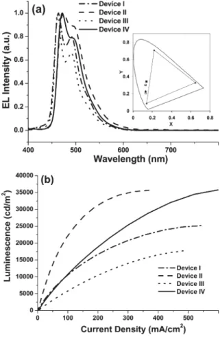
According to the EL spectra shown in Fig. 5(a), the FIrfpy-based devices (I and III) exhibit blue-shifted emissions compared with the FIrpic-based devices (II and IV), while the insert depicts the corresponding CIE coordinates. The extent of blue-shifting in the EL spectra of FIrfpy doped devices I and III (ca. 10 nm each) is similar to that observed in the PL spectra recorded in room temperature solutions. Fig. 5(b) displays the current density–luminescence (I–L) characteristics of each device; device I exhibits a maximum luminance as high as 25200 cd m22 at 16 V (500 mA cm22)
with CIE coordinates at (0.13, 0.23), which represents, so far, the brightest and best true-blue phosphorescent device to our knowledge.16,17,34 According to the plots of external quantum efficiency and luminance efficiency vs. current density shown in Fig. 6(a and b), the maximum external quantum efficiency (max. gext) of devices I and II are
calculated to be 9.4% (15.1 cd A21, 12.2 mA cm22) and 15.0% (30.6 cd A21, 18.9 mA cm22) respectively. Both have quantum efficiencies 2.2 times higher than those of the reference devices III and IV (mCP-based), which show max. gext of 4.3% (6.3 cd A21, 25.4 mA cm22) and 6.70%
(12.4 cd A21, 23.7 mA cm22), respectively. It is worth mentioning that the max. efficiencies in our devices appeared to occur in the more useful current density range of 10–20 mA cm22, in contrast to those reported for other UGH-based devices (,0.1 mA cm22). Key characteristics of
Fig. 5 (a) EL spectra of devices I–IV. Inset: the respective CIE coordinates. (b) Electroluminescence intensity vs. current density for devices I- IV.
Fig. 6 (a) External quantum efficiency vs. current density for devices I–IV, (b) luminance efficiency vs. current density for devices I–IV.
these blue phosphorescent devices are listed in Table 1. In addition, our TPSi-F based devices exhibit a much reduced degree of efficiency roll-off at high current densities; the external quantum efficiencies of devices I and II at 100 mA cm22were 6.6% and 10.9%, respectively. The high-current decline in efficiency is typical in phosphorescent OLEDs due to triplet–triplet annihilation. Apparently, the rigid cardo structure of TPSi-F provides an ideal packing environment for dispersing and isolating the phosphorescent emitters, yielding an improved efficiency via reduction of triplet–triplet annihilation of the blue dopant.
Moreover, the utilization of TPSi-F in devices I and II significantly improved their efficiencies compared with those of the mCP-based OLED devices III and IV. We attribute this to a notable enhancement in charge trapping and recombination, which is a result of the lowered HOMO energy gap for TPSi-F. It is noted that, for the typical phosphorescent OLED, it is desirable to have HOMO and LUMO energy levels of the host lying below and above those of the dopant, respectively, to ensure efficient carrier collection and recombi-nation.17Nevertheless, the HOMO level of mCP (5.9 eV) is too close to that of the sky-blue phosphor FIrpic (5.9 eV), and is unavoidably higher than that of the blue-emitting phosphor FIrfpy (6.2 eV). Notably, the cyclic voltammetry (CV) of TPSi-F reveals an estimated HOMO energy level at 6.3 eV, which is 0.4 eV lower than that of the mCP host. Conse-quently, this lower HOMO energy of TPSi-F facilitates the hole trapping at the phosphor sites, followed by recombination of opposite charges (electrons) to form excitons. Finally, it has been reported that the substituted tetraphenylsilane moiety of TPSi-F may bring a more balanced hole and electron combination process and lead to effective exciton generation in the emissive layer.34
Conclusions
In summary, we have demonstrated the successful fabrication of highly efficient true-blue phosphorescent OLEDs, employ-ing both the novel silane-based host TPSi-F and the new blue-emitting phosphorescent dopant FIrfpy. The host material TPSi-F is constructed by linking a p-substituted tetraphenyl-silane to the fluorene molecule through a non-conjugated sp3-hybridized carbon atom at the C-9 position, which enhances its thermal and morphological stabilities. Although the triplet energy of this fluorene derivative TPSi-F (2.89 eV) is slightly lower than that of carbazole and its derivatives
(y3.0 eV),14,34,35
it is still high enough to prevent the backward energy transfer from dopant to host and is suitable to serve as a host material for phosphorescent dopants such as FIrpic and FIrfpy in fabrication of blue-emitting OLEDs. The OLED device fabricated using our fluorene-based host and the more traditional dopant emitter FIrpic showed an E.Q.E. of 14.9% at 20 mA cm22, while switching the dopant from FIrpic to FIrfpy gave a blue-shifted emission with a CIE value of 0.13 and 0.23 and an E.Q.E. of 9.0% at 20 mA cm22. These TPSi-F based blue phosphorescent devices exhibited a 2-fold enhancement in the device efficiency compared with reference devices based on the mCP host material. Finally, in addition to the higher operation efficiencies, our TPSi-F based devices exhibit a less pronounced efficiency roll-off at high current densities, which is in sharp contrast to that of the UGH-based and 3,6-bis(triphenylsilyl)carbazole-based blue-emitting phos-phorescent devices.14–17,35
Acknowledgements
We thank the National Science Council of Taiwan for funding. We also thank Professor C.-H. Cheng for his generosity and permission in letting us use his OLED fabrication and measurement systems.
References
1 T. Fuhrmann and J. Salbeck, MRS Bull., 2003, 28, 354.
2 M.-T. Lee, C.-H. Liao, C.-H. Tsai and C.-H. Chen, Adv. Mater., 2005, 17, 2493.
3 E. Holder, B. M. W. Langeveld and U. S. Schubert, Adv. Mater., 2005, 17, 1109.
4 N. J. Turro, Modern Molecular Photochemistry, University Science Books, Sausalito, CA, 1991, Benjamin/Cummings, Menlo Park, NJ, 1978.
5 C. Adachi, M. A. Baldo, M. E. Thompson and S. R. Forrest, J. Appl. Phys., 2001, 90, 5048.
6 Y. Kawamura, K. Goushi, J. Brooks, J. J. Brown, H. Sasabe and C. Adachi, Appl. Phys. Lett., 2005, 86, 071104.
7 S. Lamansky, P. Djurovich, D. Murphy, F. Abdel-Razzaq, H. E. Lee, C. Adachi, P. E. Burrows, S. R. Forrest and M. E. Thompson, J. Am. Chem. Soc., 2001, 123, 4304.
8 M. Ikai, S. Tokito, Y. Sakamoto, T. Suzuki and Y. Taga, Appl. Phys. Lett., 2001, 79, 156.
9 Y.-L. Tung, S.-W. Lee, Y. Chi, Y.-T. Tao, C.-H. Chien, Y.-M. Cheng, P.-T. Chou, S.-M. Peng and C.-S. Liu, J. Mater. Chem., 2005, 15, 460.
10 F.-I. Wu, H.-J. Su, C.-F. Shu, L. Luo, W.-G. Diau, C.-H. Cheng, J.-P. Duan and G.-H. Lee, J. Mater. Chem., 2005, 15, 1035. 11 A. Tsuboyama, H. Iwawaki, M. Furugori, T. Mukaide,
J. Kamatani, S. Igawa, T. Moriyama, S. Miura, T. Takiguchi, Table 1 Performance of devices I–IV
I II III IV Voltage/Va 9.9 9.1 9.2 9.3 Brightness/cd m22 a,b 2900 (10600) 6100 (22200) 1300 (5800) 2500 (10800) E.Q.E. (%)a,b 9.0 (6.6) 14.9 (10.9) 4.2 (4.0) 6.7 (5.8) L.E./cd A21a,b 14.6 (10.6) 30.4 (22.2) 6.3 (5.8) 12.4 (10.8) Max. brightness 25200 (@ 16 V) 35700 (@ 15 V) 17800 (@ 16 V) 35900 (@ 16 V) Max. E.Q.E. (%) 9.4 15.0 4.3 6.7 Max. L.E./cd A21 15.1 30.6 6.3 12.4 EL lmax/nmc 464 474 462 472
CIE, x and yc 0.13 and 0.23 0.14 and 0.34 0.13 and 0.21 0.13 and 0.30
a
At 20 mA cm22.bThe data in the parentheses were taken at 100 mA cm22.cAt 9 V.
S. Okada, M. Hoshino and K. Ueno, J. Am. Chem. Soc., 2003, 125, 12971.
12 S. Tokito, T. Iijima, Y. Suzuri, H. Kita, T. Tsuzuki and F. Sato, Appl. Phys. Lett., 2003, 83, 569.
13 I. Tanaka, Y. Tabata and S. Tokito, Chem. Phys. Lett., 2004, 400, 86.
14 R. J. Holmes, S. R. Forrest, Y.-J. Tung, R. C. Kwong, J. J. Brown, S. Garon and M. E. Thompson, Appl. Phys. Lett., 2003, 82, 2422. 15 R. J. Holmes, S. R. Forrest, T. Sajoto, A. Tamayo, P. I. Djurovich, M. E. Thompson, J. Brooks, Y.-J. Tung, B. W. D’Andrade, M. S. Weaver, R. C. Kwong and J. J. Brown, Appl. Phys. Lett., 2005, 87, 243507.
16 R. J. Holmes, B. W. D’Andrade, S. R. Forrest, X. Ren, J. Li and M. E. Thompson, Appl. Phys. Lett., 2003, 83, 3818.
17 X. Ren, J. Li, R. J. Holmes, P. I. Djurovich, S. R. Forrest and M. E. Thompson, Chem. Mater., 2004, 16, 4743.
18 X. Zhang, C. Jiang, Y. Mo, Y. Xu, H. Shi and Y. Cao, Appl. Phys. Lett., 2006, 88, 051116.
19 Y. You, S. H. Kim, H. K. Jung and S. Y. Park, Macromolecules, 2006, 39, 349.
20 R. Ragni, E. A. Plummer, K. Brunner, J. W. Hofstraat, F. Babudri, G. M. Farinola, F. Naso and L. De Cola, J. Mater. Chem., 2006, 16, 1161.
21 A. B. Tamayo, S. Garon, T. Sajoto, P. I. Djurovich, I. M. Tsyba, R. Bau and M. E. Thompson, Inorg. Chem., 2005, 44, 8723. 22 C. S. K. Mak, A. Hayer, S. I. Pascu, S. E. Watkins, A. B. Holmes,
A. Koehler and R. H. Friend, Chem. Commun., 2005, 4708.
23 C.-L. Lee, R. R. Das and J.-J. Kim, Chem. Mater., 2004, 16, 4642.
24 K. Brunner, A. van Dijken, H. Borner, J. J. A. M. Bastiaansen, N. M. M. Kiggen and B. M. W. Langeveld, J. Am. Chem. Soc., 2004, 126, 6035.
25 T. F. Palmer and S. S. Parmar, J. Photochem., 1985, 31, 273. 26 C.-L. Chiang and C.-F. Shu, Chem. Mater., 2002, 14, 682. 27 J. J. Klappa, A. E. Rich and K. McNeill, Org. Lett., 2002, 4, 435. 28 R. Bolton, N. B. Chapman and J. Shorter, J. Chem. Soc., 1964,
1895.
29 S. R. Forrest, D. D. C. Bradley and M. E. Thompson, Adv. Mater., 2003, 15, 1043.
30 C.-H. Yang, S.-W. Li, Y. Chi, Y.-M. Cheng, Y.-S. Yeh, P.-T. Chou, G.-H. Lee, C.-H. Wang and C.-F. Shu, Inorg. Chem., 2005, 44, 7770.
31 Y.-Y. Lyu, Y. Byun, O. Kwon, E. Han, W. S. Jeon, R. R. Das and K. Char, J. Phys. Chem. B, 2006, 110, 10303.
32 J. Li, P. I. Djurovich, B. D. Alleyne, I. Tsyba, N. N. Ho, R. Bau and M. E. Thompson, Polyhedron, 2004, 23, 419.
33 V. Adamovich, J. Brooks, A. Tamayo, A. M. Alexander, P. I. Djurovich, B. W. D’Andrade, C. Adachi, S. R. Forrest and M. E. Thompson, New J. Chem., 2002, 26, 1171.
34 S.-J. Yeh, M.-F. Wu, C.-T. Chen, Y.-H. Song, Y. Chi, M.-H. Ho, S.-F. Hsu and C. H. Chen, Adv. Mater., 2005, 17, 285.
35 M.-H. Tsai, H.-W. Lin, H.-C. Su, T.-H. Ke, C.-C. Wu, F.-C. Fang, Y.-L. Liao, K.-T. Wong and C.-I. Wu, Adv. Mater., 2006, 18, 1216.