Vol. 1, No. 8/August 1984/J. Opt. Soc. Am. A 801
Three-dimensional intensity distribution near the focus in
systems of different Fresnel numbers
Yajun Li
Institute of Electro-Optical Engineering, National Chiao Tung University, 1001 Ta Hsueh Road, Hsinchu, Taiwan 300, China
Emil Wolf*
Department of Physics and Astronomy, University of Rochester, Rochester, New York 14627 It was recently shown that, when a converging spherical wave is focused in a diffraction-limited system of suffi-ciently low Fresnel numbers, the point of maximum intensity does not coincide with the geometrical focus but is located closer to the exit pupil. In the present paper both qualitative and quantitative arguments are presented that elucidate the modifications that the whole three-dimensional structure of the diffracted field undergoes as the Fresnel number is gradually decreased. Contours of equal intensity in the focal region are presented for systems of selected Fresnel numbers, which focus uniform waves.
1. INTRODUCTION
In a number of publications that appeared in recent years'-5 it was demonstrated that the classic theory regarding the structure of the focal region does not predict correct results under all circumstances. More specifically, it was found that, when a uniform, converging, monochromatic spherical wave is diffracted at a circular aperture, the classic theory is ade-quate for calculating the intensity distribution along the axis near the geometrical focus only if the Fresnel number of the
focusing geometry [defined by Eq. (2.2) below] is large com-pared to unity.6 Since before the invention of the laser the Fresnel number of a focusing system was generally much larger than unity, no discrepancies with predictions of the classic theory were then found. However, in recent years systems have been developed, especially for use with laser beams, whose Fresnel numbers are of the order of unity or even smaller. Hence it is desirable to extend the classic theory of focusing to systems of this kind.
In the present paper we present isophotes (contours of equal intensity) in the focal region in systems of different Fresnel numbers. We begin with some general qualitative observa-tions, which indicate why one must expect changes in the structure of the focal region as the Fresnel number N of the system changes gradually from large values (N >> 1) to very small values (N << 1). The qualitative arguments also indi-cate that the classic theory of focusing reaches its limit of validity for systems whose Fresnel numbers are of the order of unity and that it breaks down completely when the Fresnel number is much smaller than unity. The qualitative con-siderations, which also indicate the general trend of the changes in the structure of the focal region as the Fresnel number decreases, are confirmed by results of detailed com-putations, presented in Section 4.
Only focusing of uniform waves is considered in this paper. However, the results may be expected to be similar for focused laser beams in systems in which the size of the diffracting
aperture is comparable with or smaller than the effective cross section of the laser beam that is incident upon it.
2. SOME QUALITATIVE CONSIDERATIONS
Let us consider a uniform, monochromatic, spherical wave converging to a focus F and diffracted at a circular aperture,
of radius a, in an opaque screen. We denote by 0 the center of the aperture and by f the distance OF (Figs. 1 and 2). We assume that
(2.1)
a >> X, ()2 << 1,
where X2 is the wavelength. Let
N = a 2/Xf (2.2)
be the Fresnel number of the focusing geometry.
It follows from elementary calculations that the maximum, attained at the edge of the aperture, of the distance A between the spherical wave front through 0 and the plane of the ap-erture is, to a good approximation, given by
Amax.= a2/2f. It is seen from Eqs. (2.2) and (2.3) that
N = Amax/(X/2),
(2.3)
(2.4) i.e., the Fresnel number is equal to the value of Aax expressed in units of half wavelength. Expressed differently, N repre-sents the number of Fresnel zones (Ref. 7, Sec. 8.2) that fill the aperture when the aperture is viewed from the geometrical focus F. To obtain some indication about the order of mag-nitude of the Fresnel number in some typical cases, let us consider two simple examples. For a conventional focusing lens we might have a = 1 cm, f = 5 cm, X = 0.5 Aim, and, ac-cording to Eq. (2.2), we then have N = 4000. On the other hand, for a long-focal-length infrared laser system we may 0740-3232/84/080801-08$02.00 (© 1984 Optical Society of America
802 J. Opt. Soc. Am. A/Vol. 1, No. 8/August 1984
N >> I (Amx>>X)
A aI
0 f F
Far field: geometrical optics limit, 0 a
N<<l (Amax)<<) A aIf 0 f
j
Far field aF O $ I p * Z Fr Z azFar field: Fraunhofer diffraction limit, Xa
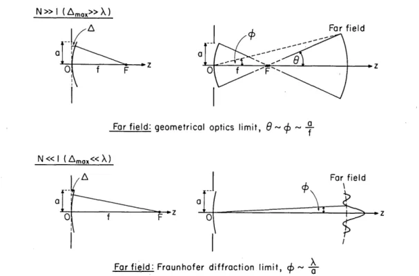
Fig. 1. Illustrating some qualitative differences in the structure of the far field generated by the diffraction of a uniform, converging mono-chromatic spherical wave at an aperture in an opaque screen in systems of large Fresnel numbers (upper figures) and low Fresnel numbers (lower figures).
have a = 1 cm, f = 3 m, X = 10 gAm, and, according to Eq. (2.2),
N = 3.3 in this case.
It is well known that for conventional focusing systems (systems with N >> 1) the maximum intensity in the diffracted field is at the geometrical focus F. Moreover, except close to the axis and in the vicinity of the edge of the geometrical shadow, the far field has the appearance of a cutoff portion of a uniform spherical wave, diverging from the geometrical focus8 9F. This "spherical cap" subtends, in each cross sec-tion through the axis OF, the angle 20 = 2a/f at F; and, be-cause it is located in the far zone, it subtends (within the ac-curacy of the asymptotic approximation of large distances from F) the angle 20 - 20 at the center 0 of the aperture:
0 - 0 = af (2.5)
(see the top right-hand diagram in Fig. 1). This structure of the far field is, of course, in agreement with predictions of geometrical optics. Y x 0 f 5
GEOMETRICAL2
FocusFig. 2. Illustrating the notation used in determining the structure of the focal region. The point Q is located on a spherical wave front
W of radius f, centered on F and passing through the center 0 of the
aperture.
Let us now consider the other extreme case, N << 1. For simplicity we will assume that the radius a of the aperture and the wavelength X have the same values as before and that the small value of N is achieved by making the distance f between the plane of the aperture and the geometrical focus be suffi-ciently large. According to Eq. (2.4) we now have Amax << X/2, and hence we are essentially dealing with the diffraction of a plane wave at the circular aperture. In such a case the far field has quite a different structure from that in systems that we just discussed (for which N >> 1). It can no longer be de-scribed by geometrical optics but rather must be dede-scribed by the theory of Fraunhofer diffraction. According to a well-known formula pertaining to Fraunhofer diffraction at a cir-cular aperture, namely, the Airy diffraction formula (Ref. 7, Sec. 8.5.2), the far field will now have a sharp maximum in the forward (axial) direction and will rapidly decrease to zero in an oscillatory manner on each side of it. The effective angular spread of the radiation is given by the order-of-magnitude relation
X
- /a. (2.6)
Since, when N << 1, we are effectively dealing with the dif-fraction of a plane wave at a circular aperture, it seems intu-itively clear that the intensity maximum will now be located in the vicinity of the center of the aperture'0 and that the diffracted field, at distances sufficiently far away from the aperture, will behave as if it had been generated by a radiating source located in the region of the aperture.
Comparison of the two extreme cases that we have just briefly discussed indicates that, as we proceed from focusing systems of large Fresnel numbers N to focusing systems of small Fresnel numbers, the intensity maximum moves from its location at the geometrical focus F to some point in the vicinity of the center 0 of the aperture. It is clear that this Y. Li and E. Wolf
Vol. 1, No. 8/August 1984/J. Opt. Soc. Am. A 803 transition is accomplished in a continuous manner. If we
assume, as seems reasonable, that the shift of the intensity maximum from its location at the geometrical focus is a mo-notonic functional of N (with a and X being kept fixed), we may conclude that with decreasing values of the Fresnel number the point of maximum intensity will move toward the center of the aperture.'2 This is indeed what was found from explicit calculations3 and was readily confirmed by experi-ment.13
In Fig. 1 the two extreme situations of systems with large and small Fresnel numbers N are illustrated by the upper and lower diagrams, respectively. They may be regarded as rep-resenting, in a sense, two modes of behavior of the diffracted field. One of the modes dominates when N >> 1, the other when N << 1. We may expect, roughly speaking, that in general there will be a mixture of these two modes of behavior and that both will significantly influence the structure of the field when the angles X, given by Eqs. (2.5) and (2.6), are of the same order of magnitude, i.e., when
a/f /a. (2.7)
If we recall the definition (2.2) of the Fresnel number N we see that Eq. (2.7) is equivalent to the condition
N 1. (2.8)
Hence our rough qualitative arguments indicate that, as the Fresnel number N of a focusing system is gradually decreased from large values (N >> 1) to small values (N << 1), we may
expect to find discrepancies with predictions of the classic theory of focusing when N attains values of the order of unity and that the classic theory will not be applicable when N has
values much smaller than unity.
We will see shortly that these rough qualitative predictions are in agreement with results of detailed calculations.
3. EXPRESSIONS FOR THE FIELD IN THE FOCAL REGION
We again consider diffraction of a uniform, monochromatic, converging spherical wave at a circular aperture of radius a in an opaque screen (Fig. 2). Let
eikf
V(M(Q, t) = A -e-it
f
(3.1)be the field distribution of the incident wave at a typical point Q on the wave front through the center 0 of the aperture. In Eq. (3.1) A is a constant and t denotes the time. With the assumptions expressed by Eqs. (2.1), the diffracted field at a point P is, according to the Huygens-Fresnel principle, given by [with the time-periodic factor exp(-iwt) omitted]
i Aeikf eiks
UN(P) = X A f Jfw ii dS, 5
(3.2) where s denotes the distance QP and the integration extends over the wave front W filling the aperture. We attached the suffix N to the symbol U(P) for the diffracted field to stress its dependence on the Fresnel number N, defined by Eq. (2.2).
Let (z, r,
4')
be the cylindrical coordinates of the field point P, referred to axes with origin at the geometrical focus F and with thez direction along OF (see Fig. 2). It is convenient to introduce the dimensionless variables'4 UN and N, which, together with4',
specify the position of the field point P:UN = 2 7rN z/f 1 + zif VN =2N rna 1 + Zif (3.3a) (3.3b) Because the field is rotationally symmetric with respect to the z axis, the diffracted field will not depend on the azimuthal angle 4'.
It was recently shown",2"15that, throughout a neighborhood of the geometrical focus, the diffracted field UN(P) may be expressed in the form
UN(P) = BN(uN)exp[ic'IN(UN, VN)I
X | J0(VNP)exp(-iUNP2/2)pdp, (3.4) where Jo is the Bessel function of the first kind and zero order,
BN(UN) = _2ri la) 1 _ UN A
X
f
ir
and 4 'N(UN, VN) = 1 u /27rN)
+ 41rNVN2
(3.5a) (3.5b) The range of validity of expression (3.4) is discussed in Ref. 15.Before proceeding further we note that the expression on the right-hand side of Eq. (3.4) is of the same mathematical form as the expression obtained by Lommel in his classic paper on the structure of the focal region,16viz.,
U(P) = B exp[i4(u)]
S
Jo(vp)exp(-iup2/2)pdp, where U=27r a\2ZX
fdz V = -X(a
r, B =- 27ri a 2A @(u) = (C)2u. (3.6) (3.7a) (3.7b) (3.8a) (3.8b) Now the following relations between the quantities UN, VN,BN, and N of the present theory and the quantities u, v, B, and <D of Lommel's theory can readily be deduced:
u 1 + u/2-rN v vN 1 + u/2-rN BN(UN) = 1- UN B, 4 ) N(UN, VN) = I 4 )(UN) + vN 1- UN/211rN IL r (3.9a) (3.9b) (3.10a) (3.10b) It follows at once from Eqs. (3.9) and (3.10) that, as N - -, with u and v being kept fixed,17
Y. Li and E. Wolf
804 J. Opt. Soc. Am. A/Vol. 1, No. 8/August 1984
UN U, VN V, (3.11) 4. THE STRUCTURE OF THE FOCAL REGION BN(UN) - B, 4 )N(UN, VN) - 4(U), (3.12)
and the expression on the right-hand side of Eq. (3.4) then reduces to Lommel's expression (3.6), i.e., as N - a,
UN(P) U(P), (3.13)
where the symbol indicates limit in the asymptotic sense. Thus we conclude that Lommel's solution represents the as-ymptotic limit of our solution for focusing systems of large Fresnel numbers.
Since the mathematical structure of the integral in ex-pression (3.4) and in Lommel's exex-pression (3.6) is the same, we may develop the integral on the right-hand side of Eq. (3.4) in the same type of series as that first employed by Lommel in analyzing consequences of his solution.'6 We then obtain for the field UN(P) in the focal region the following expres-sion:
UN(P) = (12)BN(UN)fexp[i4 )N(UN, VN)]
X [C(UN, VN) - iS(UN, VN)], (3.14) where
CN(UN, VN)= (/2) U1(UN, VN)
(UN/2)
+ (U/2) U2(UN,vN), (3.15a) (uN/2)
SN(UN, VN) = (/2) U1(UN, VN) (UN/2)
COS(UN/2) U2(UN, VN), (3.15b)
(UN/2)
and U, and U2 are two of the Lommel functions:
Uf(UN, VN)=
~
(-1). (ŽflSJn+ 2s(VN),(3.16)
S=O VN
Jm (VN) being a Bessel function of the first kind and of order m.
Although the formulas are valid in the neighborhood of the geometrical focus F, they are convenient for computations only when I uN/vNI < 1, i.e., when I z /r < f/a; this is the region
of the geometrical shadow. When I UN/VNI > 1, i.e., when I zI Ir
> f/a, the field point P is in the geometrically illuminated region, and it is then more convenient to use the following alternative expressions for the functions C(UN,VN) and
S(UN,VN) that appear in Eq. (3.14):
2 vN2 sin(UN/2) VOWNVN) UN 2UN (UN/2)
cos(uN/2) V1(N vN),
(UN/2) (3.17a)
The close formal similarity of expression (3.4) of the present theory and expression (3.6) of Lommel's theory makes it possible to draw at once some interesting conclusions.
We note that the variables u and v of Lommel's theory de-pend linearly on the two cylindrical coordinates (z, r) of the field point [Eqs. (3.7)]. On the other hand, the variables UN
and VN of the present theory are nonlinear functions of z and r [Eqs. (3.3)]. In the linear regime, the effect of changing any of the parameters X, a, or f is equivalent to scaling; i.e., if one of the parameters is changed, the field distribution U(P) is modified only in the simple manner of becoming spatially magnified (with magnification 1) in the longitudinal (z) direction or the transverse (r) direction or both. This is, however, not so with the field distribution UN(P). The nonlinear relationship (3.3) between the cylindrical coordi-nates (z, r) and the dimensionless variables (UN, VN) implies a more drastic change. This is illustrated in Fig. 3. In the top left-hand diagram of Fig. 3 a rectangular mesh formed by the z- and r-coordinate lines has been superimposed upon the well-known isophote diagram (diagram formed by contours of equal intensity I =
I
U 2) in the region of focus, calculated from Lommel's theory. Because of the linearity, the mesh also represents lines of constant values of u (vertical lines) and of constant values of v (horizontal lines). The other three diagrams in Fig. 3 show the corresponding lines UN = constant, VN = constant in focusing systems of Fresnel numbers N = 100, N = 10, and N = 1, respectively, plotted in the z, rplane.
In Fig. 4 the isophotes IN = I UNI 2 = constant, normalized to unity at the geometrical focus, are shown for focusing sys-tems of selected Fresnel numbers. We see that with de-creasing N, the point of maximum intensity moves from its coincidence with the geometrical focus toward the center of the aperture and that the isophote diagrams approach more and more those of a complicated radiation field generated by a source in the vicinity of the center of the aperture. These quantitative results are in agreement with the conclusions that we reached by rough qualitative arguments in Section 2.
Finally we note that, when the point P(z, r, 4') is located in the geometrical focal plane z = 0, one has, according to Eqs.
(3.3), (3.7), and (2.2),
UN = U = 0, VN = V, (4.1)
BN(0) = B, 4 )N(0, VN) = 4)(0) + N v 2.
471N (4.2)
On substituting from Eqs. (4.1) and (4.2) into Eq. (3.4) and on comparing the resulting expression with Eq. (3.6) we see that
2 i v 2 UN(P)IZO0 = U(P)Iz=0o exp i _
47-NI (4.3)
S(uN vN) =
-2
cosVN2 COS(UN/2) Vo(u VN) UN 2UN (UN/2)sin(UN/2) V1(UN, VN), (3.17b)
(UN/2)
where Vo and V1are two of the Lommel functions1 8:
VfSuNvN
~O
= Nln+2sJn+2s(VN). (3.18)This formula implies that, irrespective of the value of the Fresnel number N, the amplitude of the field at any point in the geometrical focal plane has the same value as given by Lommel's theory and that the corresponding phase factor differs from the phase factor of Lommel's theory by the amount v2/4rN. It is an immediate consequence of the first of these two results that, irrespective of the Fresnel number N of the system, the intensity distribution in the focal plane Y. Li and E. Wolf
Y. Li and E. Wolf Vol. 1, No. 8/August 1984/J. Opt. Soc. Am. A 805 N 1 . a I0 - .6 4 4~~~~~~~~~~~~II 4-1i
It
tf4
-la I I 6 0 I, - - 4----4
-- 4
I
- .N -1 W ' m m m m 40 I-.4 i. -10I
w~f
0 . 10 0 in~~
z
4 L--j~~~~~-i (E0c U I-'4 N 1~~~~~0 b .3 0~~~~~~ .a)~
' 44 0 A -p.. 4~~~~~~~C N U)~~~~~~~~~~~~Io~~~~~~~~~~~~~~C
CY ~ ~ ~ ~ 000 In. bB 08Ci .m Im- A I coe
m m04 NI 40HC Ie
M oml- I Uco I MI I-Ij
-!o
IT
0 0 Z -Z 'CC S .-a 0 4 4t - - l - -- -- -- -- -- - -v . i V I , I , -, I . , e nCII
-Ml i ,E , CQ co co - 10 - V I I I I ,806 J. Opt. Soc. Am. A/Vol. 1, No. 8/August 1984 Y. Li and E. Wolf
±C)
,- T 0 0
808 J. Opt. Soc. Am. A/Vol. 1, No. 8/August 1984
is given by the Airy-pattern formula [Ref. 7, p. 441, Eqs. (25)
and (22)]
IN(p)JZ-O-IUN
_0=JUN=
(P~l2=o =2J,(V)]2vpJ 10 (4.4)where
Io t= a 2 2
(4.5) is the intensity at the geometrical focus.
ACKNOWLEDGMENTS
The main part of this research was carried out while E. Wolf was on leave of absence at Schlumberger-Doll Research in Ridgefield, Connecticut. Preliminary results were presented on October 22, 1982, at the Annual Meeting of the Optical Society of America in Tucson, Arizona [J. Opt. Soc. Am. 72, 1818 (A) (1982)].
* E. Wolf is also with the Institute of Optics, University of Rochester.
REFERENCES
1. J. H. Erkkila and M. E. Rogers, "Diffracted fields in the focal volume of a converging wave," J. Opt. Soc. Am. 71, 904-905 (1981).
2. J. J. Stamnes and B. Spjelkavik, "Focusing at small angular ap-ertures in the Debye and Kirchhoff approximations," Opt. Commun. 40, 81-85 (1981).
3. Y. Li and E. Wolf, "Focal shifts in diffracted converging spherical waves," Opt. Commun. 39, 211-215 (1981).
4. Y. Li, "Dependence of the focal shift on Fresnel number and f number," J. Opt. Soc. Am. 72, 770-774 (1982).
5. M. P. Givens, "Focal shifts in diffracted converging spherical waves," Opt. Commun. 41, 145-148 (1982).
6. Similar results were also found in connection with focused Gaussian beams. For a discussion of this subject and for perti-nent references, see Y. Li and E. Wolf, "Focal shift in focused truncated Gaussian beams," Opt. Commun. 42, 151-156
(1982).
7. M. Born and E. Wolf, Principles of Optics, 6th ed. (Pergamon, Oxford, 1980).
8. E. Wolf and Y. Li, "Conditions for the validity of the Debye in-tegral representation of focused fields," Opt. Commun. 39, 205-210 (1981).
9. G. C. Sherman and W. C. Chew, "Aperture and far-field distri-butions expressed by the Debye integral representation of focused fields," J. Opt. Soc. Am. 72, 1076-1083 (1982).
10. In this connection it seems worthwhile to mention that none of the currently available theories of diffraction at an aperture in an opaque screen appears to be adequate to predict the structure of the diffracted field in the near zone of the aperture; nor are any
experimental results available to elucidate this question. 11. For the same reason as indicated in Ref. 10, this assumption may
not be valid when the maximum reaches the immediate vicinity of the aperture.
12. A somewhat paradoxical aspect of this situation should be noted. As the Fresnel number N becomes smaller, with a and A being
kept fixed, the distance f increases, i.e., the geometrical focus F moves farther away from the aperture; however, the point of maximum intensity moves in the opposite direction, i.e., closer to the aperture.
13. Y. Li and H. Platzer, "An experimental investigation of diffraction patterns in low-Fresnel-number focusing systems," Opt. Acta 30,
1621-1643 (1983).
14. The choice of these variables is suggested by detailed calculations given, for example, in Ref. 15. As will be seen shortly, they reduce to the usual dimensionless variables of the classic theory of Lommel in the limit of large Fresnel numbers.
15. Y. Li, "Encircled energy for systems of different Fresnel num-bers," Optik 64, 207-218 (1983).
16. E. Lommel, "Die Beugungserscheinungen einer kreisrunden Oeffnung und eines kreisrunden Schirmchens," Abh. Bayer. Akad. Math. Naturwiss. Kl. 15, 233-328, (1885). The main part of Lommel's analysis is presented (in English) in Sec. 8.8 of Ref. 7.
17. This limiting procedure is equivalent to keeping the field point
P(z, r, O) as well as the wavelength X and the angular semiap-erture a/f fixed and letting f - a). That the resulting expression
is to be interpreted as an asymptotic rather than an ordinary approximation is strongly suggested by recent discussions of the Debye representation of focused fields,8'9which is known to be equivalent to Lommel's representation under the usual circum-stances.
18. When the suffix n is a negative integer, Lommel's original defi-nition of the function V,, differs from that given by Eq. (3.18) by a factor (-1) n.
19. E. H. Linfoot and E. Wolf, "Phase distribution near focus in an aberration-free diffraction image," Proc. Phys. Soc. London Sect. B 69, 823-832 (1956).