Design and Implementation of a Zigbee-based Communication Substrate for Wireless Sensor Networks
13
0
0
全文
(2) performance result shows that the throughput of. describe the design issues and implementation. the network layer can reach 88 Kbps, which is. details of the Zigbee network layer, which plays. sufficient for most WSNs.. the roles of network formation, joining, leaving, and packet routing, and it can act as a. Keywords: Wireless Sensor Network, Zigbee,. communication substrate of a WSN. In a Zigbee-based WSN, multiple devices. IEEE 802.15.4.. may send beacons periodically, and hence a. 1. Introduction. beacon scheduling algorithm is needed to avoid. Wireless Sensor Network (WSN) [1, 3, 13]. beacon collision. In this paper, we propose a. has received much attention in recent years. A. beacon scheduling algorithm, which has been. WSN consists of a large number of sensor nodes. embedded into our Zigbee network layer. that can communicate and cooperate with each. implementation.. other to accomplish a specific task. One of the. In addition to the Zigbee network layer,. most important requirements of a WSN is that. we also developed an object-tracking application. sensor nodes should be low power, both in. based on this layer. The application can be. computation and communication, so that long. integrated into a health-caring system for. battery life is allowed.. watching aged people in a community or a. Zigbee [15] is a wireless communication. student-tracking system that tracks students. technology for wireless personal area network. when they are in the path between their homes. (WPAN). It is especially suitable for low-power. and the school. In order to support fast object. sensing and control applications. The Zigbee. tracking, we propose a technique that take. protocol stack, which consists of the network. advantage of the functionality provided by. and application layers, sits on top of the MAC. Zigbee/IEEE. and PHY layers defined by the IEEE 802.15.4. implemented the technique and demonstrate its. [11] standard. Due to the low power and low. feasibility and performance.. 802.15.4. network.. We. also. cost features of a node, Zigbee is becoming an. We have implemented the Zigbee network. emerging standard for the communication. layer as a Linux kernel module on the SCAN. technology of WSNs. For example, the MICA. sensor board, which is developed by Industrial. sensor series contains a product MICAz [5] that. Technology Research Institute (ITRI). According. is. IEEE. to the performance results, the proposed object. 802.15.4-compliant RF transceiver. For another. tracking approach is efficient and the data. example, there are also efforts [12] that. throughput of the network layer (i.e., 88 Kbps) is. implement Zigbee stack on TinyOS[14], the. sufficient for most WSNs.. equipped. with. a. 2.4. GHz. most popular operating system for WSNs.. The sensor board together with the Zigbee. Although Zigbee has become a promising. protocol stack can serve as a research platform. candidate for the communication technology of. for WSN. Different from the TinyOS platform, a. WSNs, the implementation details are still not. sensor node application on our platform is a. mentioned in the literature. In this paper, we. typical. Linux. application. program.. Thus,.
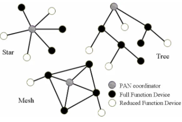
(3) researchers can implement their techniques with. 802.15.4 defines the MAC and PHY layers for a. less effort.. low data rate WPAN. It uses carrier sense. The remainder of the paper is organized as. multiple. access. with. collision. avoidance. follows. Section 2 describes the related efforts.. (CSMA-CA) as the medium access mechanism,. Section 3 presents the design issues and. and it can achieve 250kbps on the 2.4 GHz ISM. implementation details. The performance results. band (16 channels).. are given in Section 4, and we conclude in. Due to the low power feature and standardization,. Section 5.. some. companies. such. as. Crossbow[4] and Freescale[9] have developed. 2. Related Work. IEEE 802.15.4-compliant sensor boards.. 2.1 Wireless Sensor Network. 2.3 Zigbee. Wireless Sensor Network (WSN) [1, 3, 13]. Zigbee [15] is a low data rate wireless. has received a great attention in recent years,. communication technology for wireless personal. both from academy and industry. Typically, a. area network (WPAN). It is defined by the. sensor node consist of a sensor unit (e.g., a. Zigbee Alliance, and is especially suitable for. temperature sensing module), a less-powerful. low-power sensing and control applications. As. computation unit (e.g., ARM, 8051), a small. mentioned above, the Zigbee Alliance defines. storage unit (e.g., Flash memory), and a. the network and application layer protocols, and. low-power communication unit. Due to the large. it chooses IEEE 802.15.4 as the bottom layers.. number and tight resource and power constraints. A Zigbee node can be a full function. of sensor nodes, WSN put challenge on solving. device (FFD) or a reduced function device. the. deployment,. (RFD). The former is equipped with more. energy-efficient routing, reprogramming, and. resources. It can send beacons, form an IEEE. etc.. 802.15.4 network, and route packets. The latter. problems. such. as. Traditionally, sensor nodes communicate. has fewer resources and usually can not perform. with each other via proprietary RF links. To. the above tasks. The nodes in a Zigbee network. enable communication among nodes from. can be classified into three roles: coordinator,. different vendors, a standard communication. router, and end device. A FFD can play any one. link is necessary. Zigbee has features such as. of the roles, while a RFD can only play the end. low cost and low power consumption so that it. device role. In Zigbee, the network topology can. has been considered as the promising candidate. be star, mesh, or cluster tree. Figure 1 shows. for the communication technology of WSN.. some possible topologies of a Zigbee network.. 2.2 IEEE 802.15.4 As mentioned above, Zigbee chooses IEEE 802.15.4. as the bottom layers of the protocol stack. The specification of IEEE.
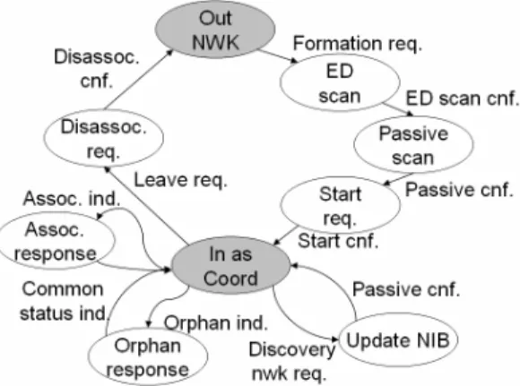
(4) Zigbee network or not, and the role of that node. For example, the Out NWK state is the initial state and indicates that the node is not in a network. The In as Coordinator state indicates that the node is currently in a Zigbee network and acts as the network coordinator. From Figure 2 we can see that, a coordinator transfer from the initial state (i.e., Figure 1. Possible Topologies of a Zigbee. the Out NWK state) to the In as Coordinator. Network. state via four steps. First, it receives the network formation request from the application layer,. Although companies such as Ember [7]. enters into the energy detection (ED) scan state,. and Figure 8 Wireless [8] have implemented a. and performs the ED scan procedure. When. full Zigbee stack, little implementation details. receiving a network formation request, the node. were mentioned. In this paper, we describe the. tries to start a WPAN. Therefore, it performs ED. design issues and implementation details of the. scan first to find out the channel with the least. Zigbee network protocol, which serves as the. signal energy among all the available channels.. communication substrate of a WSN.. The node will try to form a WPAN on that channel. Second, when an ED scan confirmation. 3. Design and Implementation. is received from the MAC layer (i.e., indicates. The Zigbee network layer is implemented. that the ED scan procedure is done), the node. as a state machine, which is described in Section. enters the passive scan state and performs the. 3.1. Section 3.2 shows the interface provided by. passive scan procedure. Through the procedure,. the network layer to the other layers. Section 3.3. the node can learn the PAN identifiers (PAN IDs). mentions some important data structures used in. that are currently used by the other WPANs on. the network layer. The beacon scheduling. the target channel, and then the node can select. algorithm and the fast object-tracking technique. an available PAN ID. Third, when the passive. are described in Section 3.4 and 3.5, respectively.. scan confirmation is received from the MAC, the. Finally, we mention the implementation of the. node enters the start request state, and sends a. applications.. start request to the MAC so that periodic beacons will be scheduled for transmission by. 3.1 State Machine As we mentioned above, a Zigbee node plays one of the three roles: coordinator, router, or end device, and we implemented a state machine for each role. Figure 2 shows the state machine of a Zigbee coordinator. The states colored in gray indicate whether the node is in a. the MAC. Fourth, when the start request confirmation is received, the node enters into the In as Coordinator state..
(5) mentioned in Figure 2, the passive scan procedure of a router scans all the available channels and returns the PAN information (such as PAN ID, channel number) on these channels. According to the information, the application layer chooses a PAN that it wishes to join into and issues a join request (that specifies the join as router option) to the network layer. When receiving the join request, the network layer Figure 2. State Transition in a Coordinator. selects a node with the strongest signal strength in the target PAN and associates with it by. It is worth mentioning that the state. issuing an association request to the MAC layer.. transition happens according to the management. Then, the start router request is issued and the. flow, not the data flow. In other words, data. router enters into the In as Router state. Note. packet transmission/reception does not lead to. that the router may send periodic beacons or not,. state transition. Data transmission/reception can. according to the parameters specified in the start. happen at anytime as long as the node is in the. router request.. network (i.e., the node is in one of the In as. In addition to the normal join operation,. Coordinator, Association Response, Update NIB,. Zigbee also contains a re-join operation, which. and Orphan Response states in Figure 2).. can. be. used. to. re-associate. with. a. coordinator/router that the node had already associated with but the link was once broken. The re-join operation triggers the orphan scan procedure of the MAC, which is typically much faster than the normal association procedure. We use this feature to enable fast object tracking, which is described more clearly in Section 3.5. When a coordinator/router enters into a network, it can allow others to join with it. When receiving an association indication from the Figure 3. State Transition in a Router. MAC, the coordinator/router checks whether or not to allow the remote device to join into the. Figure 3 shows the state transition of a. network. If the device is allowed, the network. Zigbee router. During the initialization of a. layer will assign a network address for the. router, the application layer issues a network. device. When an orphan notification is received,. discovery request to the network layer, which. the network layer checks whether or not the. triggers a passive scan procedure. Slightly. remote device had already associated with the. different from the passive scan procedure. local node. If it had, the network layer assigns.
(6) the same network address for the remote device. As mentioned above, Zigbee network layer. so that the remote device can enter the network. sits between the application layer and the MAC. again.. layer. The inter-layer communication is via messages. Figure 5 shows the inter-layer interface, which is defined by [10]. The interface is divided into data and management parts, and the network layer provides four APIs to the other layers:. APL_NLDE/APL_NLME. application. layer,. for. the and. MCPS_NWK/MLME_NWK for the MAC layer. These APIs are used by the application and Figure 4. State Transition in an End Device. MAC layers to transfer messages to the network layer. When a message is received, the network. Figure 4 shows the state transition of a. layer inserts the message into the corresponding. Zigbee end device. The states are a subset of. queue to allow the state machine to process the. those. message.. shown. in. Figure. 3.. During. the. initialization of an end device, the application. The network layer checks the message. layer also issues a network discovery request to. queues periodically to see if there are any. the network layer, which triggers a passive scan. pending messages. If there are, it removes the. procedure and therefore the node can associate. first message from the queue and uses the. with a coordinator/router it chooses.. message as the input of the state machine. The. Whatever the role a node plays, an. state machine will process the message, and. in-network node can leave the network when it. perform state transition when necessary. Then,. receives a leave request form the application. the memory used by the message will be freed. layer. The request triggers the disassociation. and the network layer will check the next. procedure of the MAC to leave the network.. pending message. Figure 6 shows the structure of the. 3.2 Inter-Layer Communication. message transferred from the application layer to the Network Layer Management Entity (NLME). Basically, each message contains message type and message data. Other kinds of messages are similar to that shown in Figure 6 so we do not describe them in the paper.. Figure 5. The Inter-Layer Interface.
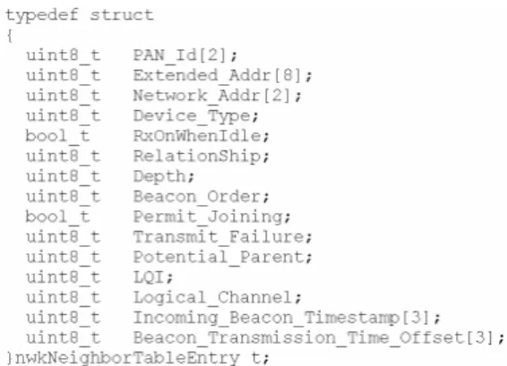
(7) Figure 6. Application-to-NLME Message Figure 8. Neighbor Table Entry. 3.3 Important Data Structures In addition to the message structure, the. 3.4 Beacon Scheduling. most important data structure is the network. As mentioned before, multiple routers (and. layer information base (NIB), which stores the. the coordinator) may send periodic beacons. A. status of the network, the routing table, and the. beacon scheduling algorithm can be used to. state of the neighbor nodes.. select the starting time of the beacons so that. Figure 7 shows the data structure of NIB.. beacon collision can be avoided.. It consists of the information such as the. The most important parameters of a. maximum depth of the network, the maximum. beacon scheduling algorithms are beacon order. number of the router, a neighbor table, and the. and superframe order. The former represents the. capability of the node.. time interval between two successive beacons, while the latter stands for the actual time period managed by the router (i.e., the router sends a beacon at the start of this period, and routers and end devices under this router can send/receive packets to/from the router in this period). Note that, in IEEE 802.15.4, the beacon order time is 2’s power times to the supreframe order time. For example, if the value of beacon. Figure 7. The NIB. order is 5 and the value of supreframe order is 2, there can be 25-2 (i.e., 8) superframes in the. The structure of a neighbor table entry is. beacon order time. Thus, we can regard the. shown in Figure 8. It consists of PAN ID,. superframe order time as a time segment, and. address information, device type (coordinator,. therefore the goal of a beacon scheduling. router, or end device), relationship between the. algorithm is to allocate an unused segment (from. local and the remote nodes, the signal strength,. all the available segments in the beacon order. and etc.. time) to the current router. When a segment is allocated to a router, the router can send a beacon at the starting time of the segment..
(8) To find an unused segment, the router must first collect all of the beacons it can receive, Gray node. and find out the segments that are used by these beacons. However, only considering the beacons. Black node. White node. the router can receive may suffer from the hidden node problem. As shown in Figure 9, if Figure 9. The Hidden Node Problem. the white node is a router that wants to join with the gray node, it may receive beacons from the gray node and select a segment which is different from that used by the gray node. However, the segment may be overlaps with that. c: current interval b: beacon order interval B: an array of segments in the beacon. of the black node, which is a hidden node of the. interval. white node, so that collisions may happen when both the black node and the white node wants to send beacon/data frames to the gray node. To avoid this problem, the Zigbee network layer embeds TxOffset values in the payload of a. collect the beacon information (including the TxOffset information) mark all used beacon segments in B let c = b / 2. /* half of the beacon. beacon, which indicate the timing differences between the beacon and the neighboring beacons. By considering the TxOffset values, a beacon scheduling algorithm can avoid the problem of hidden nodes. Take Figure 9 as an example, the. interval*/ while(c >= 1) { check all segments with segment number i*c in B ( where 0 <= i <= b/c -1 ). beacon of the gray node embeds a TxOffset. if an unused segment is found. value, which indicates the timing difference. return the segment number. between the beacon of the gray node and the. else. beacon of the black node. When receiving the beacon (from the gray node), the white node can learn the time segments of both the gray and the black nodes according to the receive time of the. c = c/2 } /* all segments are used */ return “no available segment”. beacon and the TxOffset value. Therefore, the white node can choose a time segment that is. Figure 10. Beacon Scheduling Algorithm. different from those of the black and gray nodes. Figure 10 shows the proposed beacon scheduling algorithm. We take an example to make the readers understand the algorithm more easily. Assuming that the there are 8 (i.e., 23) segments in a beacon order time. This algorithm first check segment 0 and 4 (i.e., multiple of 22),.
(9) then segment 2 and 6 (multiple of 21), and finally segment 1, 3, 5, 7 (multiple of 20). The algorithm returns the unused segment number that it finds first.. 3.5 Fast Object Tracking Some WSN applications require tracking Figure11. Orphan Join. the location of specific moveable sensor nodes. In this section, we describe the approach that we used to track a Zigbee-based sensor node (i.e., object).. 3.6 Application Implementation In. the. initial. implementation,. the. When a Zigbee-based object moves from. application is linked together with the Zigbee. the radio range of a node to that of another node,. network layer as a Linux kernel module.. the object usually has to perform association. Therefore, the communication between the. with the new node. However, association. application and the Zigbee network layer is. requires a long time, so we use orphan join. through function calls.. operation instead. As shown in Figure 11, the. To make application development easier, we. object will broadcast orphan request command,. currently allow the applications to be executed. which will be received by router R1, R3, and R4. in user mode. We have wrapped the Zigbee. since they are in the radio range of the object.. network layer as a character device so that an. The object will join into one of the routers (i.e.,. application can perform communication via. become the child of the router), and all the above. Zigbee by simply accessing the character device. routers can send packets to the coordinator to. file. Specifically, an application can send. specify that the object is in the radio ranges of. commands/data to the Zigbee network layer by. the routers. Each router can also record the. performing ioctl() calls. On the other hand, the. signal strength of the received packet and pass. Zigbee network layer notifies the application by. the information to the coordinator so that more. using Linux signals. We reserve two signal. precise positioning is possible.. numbers for Zigbee applications. SIGUSR1 is. We will demonstrate that the orphan join operation outperforms the association operation. used by the management flow, and SIGUSR2 is used by the data flow.. in time in Section 4.3.. 4. Evaluation 4.1 Experimental Environment We use the SCAN ZB V1.0B sensor boards. developed. by. Computer. and. Communication Research Laboratory (CCL) at Industrial Technology Research Institute (ITRI) as our sensor devices. Each sensor board is.
(10) equipped with a Hynix HMS30C7202 CPU (70MHz), 16-MByte Flash, 16-MByte DRAM, and a Chipcon CC2420 RF Transceiver. The operating system is Linux, version 2.4.21. The MAC layer, which we use in the following. experiments,. Computer. Systems. is. developed. Laboratory. at. by. Figure 12. Object Tracking (Initial Condition). CSIE. Department of Chang Gung University. In addition to this MAC, our Zigbee network implementation was also ported to the D18 MAC,. the. IEE. 802.15.4-compliant. MAC. developed by Freescale Semiconductor Inc. Besides the sensor nodes, we also use a packet sniffer CC2420EB [2] developed by. Figure 13. Object Tracking (Final Condition). Chipcon Inc. in some of the following experiments.. 4.3 Performance of Orphan Join In. 4.2 Object Tracking To demonstrate the feasibility of the object. this. section,. we. measure. the. performance of orphan join, and compare it with the performance of association.. tracking, we build up a backbone network that consists of three nodes: one coordinator and two. 4.3.1 Orphan Join v.s. Association. routers. As shown in Figure 12, device 0000 is. To measure the performance, we have an. the coordinator, while devices 0001 and 0002 are. end device associate (or orphan join) with the. the routers. This figure is presented by the. coordinator and measure the time of the whole. packet sniffer with the Network Sensor Analyzer. procedure on the end device. Figure 14 shows. software [6] developed by Daintree Netwrok. the results. From the figure we can see that the. Inc., which is used to visualize the network. association time is about 9 times more than the. topology. In addition to the backbone, there are. orphan join time. This proves that the orphan. three moveable objects that need to be tracked.. join. Originally, the three objects join with the. performance.. coordinator. During the experiment, we move the objects from the original position to the radio range of router 0001, and then to the radio range of router 0002. Figure 13 shows the result. From the figure we can see that, the objects finally join with router 0002.. outperforms. association. in.
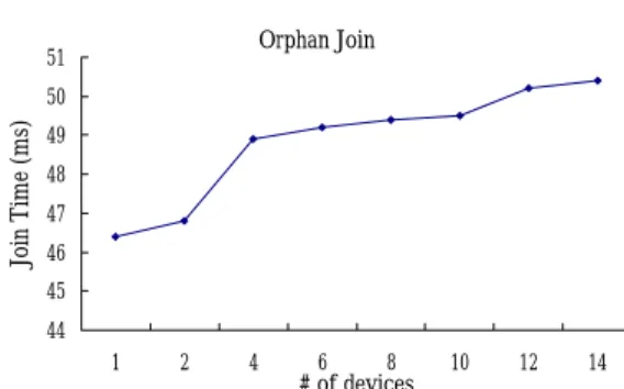
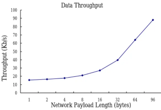
(11) unavailability of more device hardware. In the. Join Comparison. more devices.. 400 350 300 250. Associate. 200 150. Orphan. Orphan Join. 51 50. 100 50. 46.44. Join Time (ms). Processing Time (ms). future, we will perform this experiment again for 428.54. 450. 0. Enddevice. 49 48 47 46 45. Figure 14. Performance Comparison between. 44 1. Orphan Join and Association. 2. 4. 6. 8. # of devices. 10. 12. 14. Figure 15. Performance of Orphan Join with Multiple Nodes. Note that most of the time an end device spends in an orphan join procedure is to wait for the response of the coordinator. In current. 4.3.3 Timing Breakdown. implementation, we use a fixed waiting time of 5 jiffies (on Linux) which equals to 45ms in. Table 1. Orphan Join Timing Breakdown Primitive NWK_TX MAC_TX Wait Time MAC_RX NWK_RX System. average. In the future, we will let an end device terminate the procedure once it has received a response from any coordinator or routers. This reduces the time of the procedure further.. Time(us) 60 341 45937 10 53 53. 4.3.2 Orphan Join with Multiple Nodes In. this. section,. we. measure. the. performance of orphan join when multiple nodes join into the same coordinator at the same time. Figure 15 shows the results. The x-axis indicates the number of nodes, while the y-axis represents the average time of the procedure measured on the end devices. From the figure we can see that about 46ms is required when there is a single end device join with the coordinator, and only. In this section, we provide a timing breakdown of the orphan join procedure, which includes sending a request to and receiving a response from the coordinator. Table 1 shows the result. As mentioned above, most of the time is spent on waiting for the response. The real processing time (including the network layer, the MAC layer and the operating system) is quite small.. about 50 ms is required when there are 14 devices. This demonstrates that the performance does not degrade much when there is a moderate number of end devices join with the same coordinator/router. We did not measure the performance for more devices due to the. 4.4 Data Throughput In this section, we measure the data throughput with the presence of the network layer. Figure 16 shows the results. As shown in the figure, the data throughput increases as the size of the payload grows, and the maximum.
(12) 5. Conclusions. through reaches 88 kbps.. In this paper, we have described the design and implementation of the Zigbee network layer,. Data Throughput. 100. which. 90. Throughput (Kb/s). 80. is. responsible. for. network. formation/joining/leaving and packet routing. In. 70 60. addition, we also proposed a beacon scheduling. 50 40. algorithm for avoiding the beacon collision. 30. problem. Finally, we proposed using the orphan. 20 10. join operation to achieve fast object tracking in a. 0 1. 2. 4. 8. 16. 32. Network Payload Length (bytes). 64. 96. Zigbee WSN. We have implemented the Zigbee network. Figure 16. Data Through under Different. layer as a Linux kernel module. According to the. Payload Sizes. performance. results,. the. proposed. object. In the last experiment, we measure the. tracking approach is efficient and the data. throughput degradation due to the adding of the. throughput of the network layer (i.e., 88 Kbps) is. Zigbee network layer implementation. The right. sufficient for most WSNs.. bar of Figure 17 indicates the maximum. The sensor board together with the Zigbee. performance of the MAC, while the left bar. implementation can serve as a research platform. represents the maximum performance under the. for WSN. Different from the TinyOS platform, a. situation. sensor node application on our platform is a. that. the. Zigbee. network. layer. implementation is added on top of the MAC. As. typical. Linux. application. program.. Thus,. shown in the figure, the throughput degradation. researchers can implement their techniques with. is about 9 kbps, which comes mainly from. less effort.. queuing delay and network layer header processing.. References [1]. Throughput (Kb/s). F.. Akyildiz,. W.. Su,. Y.. Sankarasubramaniam and E. Cayirci, “A. 120 100. L.. 97. Survey on Sensor Networks”, IEEE. 88.1. 80. Communication Magazine, Vol. 40, No. 8,. NWK 60. MAC. pp. 102-114, August 2002.. 40. [2]. Chipcon. Inc.,. “CC2420. Zigbee. DK. available. at. 20 0. Development Layer. Figure 17. Performance Impact of Adding the Zigbee Network Layer. Kit”,. http://www.chipcon.com/index.cfm?kat_id= 2&subkat_id=12&dok_id=176, 2005. [3] C. Y. Chong and S. P. Kumar, “Sensor Networks: Evolution, Opportunities, and Challenges”, Proceedings of the IEEE, Vol. 91, No. 8, pp. 1247-1256, August 2003..
(13) available. [4] Crossbow Technology Inc., the Company. at. http://www.. Web Site of Crossbow Technology Inc.,. luxoftlabs.com/tiki-index.php?page=ZigBee. available at http://www.xbow.com/, 2005.. %20Stack, 2005.. [5] Crossbow Technology Inc., MICAz datasheet,. [13] V. Rajaravivarma, Y. Yang and T. Yang, "An. at. overview of Wireless Sensor Network and. http://www.xbow.com/Products/Product_pdf. applications", IEEE Proceedings of the 35th. _files/Wireless_pdf/MICAz_Datasheet.pdf,. Southeastern Symposium on System Theory,. 2005.. pp.432-436, 2003.. available. [6] Daintree Networks, Inc., “Daintree Network Analyzer. Software”,. http://www.daintree.. available. net/products/sna.htm,. TinyOS. Web. Site,. available. [15]. Zigbee. Alliance,. available. http://www.zigbee.org/, 2005.. [7] Ember Corporation, "EmberZNet? 2.0 - Fact Sheet. ",. available. at. http://www.ember.com/products/software/zi gbee2.html, August 2005. [8] Figure 8 Wireless, Inc., "ZigBee Software Development. Suite",. available. at. http://www.figure8 wireless.com/DataSheet.pdf, 2005. [9] Freescale Semiconductor Inc., the Company Web Site of Freescale Semiconductor Inc., http://www. freescale.com, 2005. [10] Freescale Semiconductor Inc., “802.15.4 MAC/PHY Software Reference Manual”, available. at. http://www.freescale.com/files/rf_if/doc/ref _manual/802154MPSRM.pdf, May 2005. [11] IEEE, IEEE standard for information technology. -. telecommunications. and. information exchange between systems and. metropolitan. area. networks. specific requirements part 15.4: wireless medium access control (MAC) and physical layer (PHY) specifications for low-rate wireless. personal. area. networks. (LR-WPANs), 2003. [12] Luxoft Labs., The Zigbee Stack Page,. at. http://www.tinyos.net/, 2005.. at. 2005.. local. [14]. at.
(14)
數據

+5
相關文件
We have presented a numerical model for multiphase com- pressible flows involving the liquid and vapor phases of one species and one or more inert gaseous phases, extending the
If a DSS school charges a school fee exceeding 2/3 and up to 2 & 1/3 of the DSS unit subsidy rate, then for every additional dollar charged over and above 2/3 of the DSS
This paper presents (i) a review of item selection algorithms from Robbins–Monro to Fred Lord; (ii) the establishment of a large sample foundation for Fred Lord’s maximum
In this paper, we build a new class of neural networks based on the smoothing method for NCP introduced by Haddou and Maheux [18] using some family F of smoothing functions.
Performance metrics, such as memory access time and communication latency, provide the basis for modeling the machine and thence for quantitative analysis of application performance..
• A sequence of numbers between 1 and d results in a walk on the graph if given the starting node.. – E.g., (1, 3, 2, 2, 1, 3) from
Type case as pattern matching on values Type safe dynamic value (existential types).. How can we
For a directed graphical model, we need to specify the conditional probability distribution (CPD) at each node.. • If the variables are discrete, it can be represented as a
