The Improvement of Tri-Plate Line Performance By
Using Corrugated Transitions
Ruey Bing Hwang, Member, IEEE
Abstract—A novel structure is investigated for the improvement
of tri-plate line (TPL) performance. Based on experience in the design of horn antennas, we introduce corrugations of the tran-sition section of the TPL in order to achieve better field uniformity and to reduce the return loss. A corrugated transition waveguide may be viewed as the cascade of bifurcated metal waveguides. We employed the building-block approach, which breaks the overall structure into cascaded subcells, each of which may be analyzed rigorously by the mode-matching method. Thus, the input–output relation of each subcell is obtained as well as that of the overall structure. This enables us to carry out a parametric study on the field distribution inside the TPL test fixture, so that we can opti-mize its design for any required specifications.
Index Terms—Bifurcation, corrugated transitions, method of
mode matching, tri-plate line (TPL).
I. INTRODUCTION
A
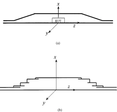
CCORDING to the recommended practice SAE J1113-25 “electromagnetic compatibility measurement procedure for vehicle components-immunity to radiated electromagnetic fields 10-kHz to 200-MHz tri-plate line (TPL) method,” [1], [2] a TPL is employed to facilitate the testing of automotive electronic components such as transmission control modules, sensors, and the other subsystems associated with wire har-nesses. A TPL looks like a Crawford cell without side walls [10], as shown in Fig. 1(a). It is designed to generate a uniform electric field in the transverse plane for electromagnetic sus-ceptibility (EMS) testing [3], [6], [7]. The fields are transferred through a taper transition from a small parallel-plate waveguide to a large one in which the equipment under test (EUT) is placed [4]. However, the shape of taper transition should be well designed to maintain the field uniformity inside the uniform region as well as to reduce the return loss [5].In this paper, the taper transition of a TPL is viewed as a horn antenna and the technique of a corrugated horn antenna is em-ployed for the design of a TPL with fins. We observe that a TPL with fins may be considered as the cascade of different subcells, each of which contains a finite length of uniform metal wave-guide and a bifurcated metal wavewave-guide. To simplify the for-mulation of this problem, we adapt the building-block approach such that the input–output relation of each subcell is obtained Manuscript received September 3, 1999; revised May 23, 2000. This work was supported by the National Science Council under Contract NSC 89-2213-E009-074 and by the Ministry of Education and the National Science Council, R.O.C., under Contract 89-E-FA06-2-4.
The author is with the Microelectronics and Information Systems Research Center, National Chiao-Tung University, Hsinchu, Taiwan 300, R.O.C. (e-mail: rbhwang@eic.nctu.edu.tw).
Publisher Item Identifier S 0018-9375(00)10200-5.
(a)
(b)
Fig. 1. Structural configurations. (a) Conventionally used TPL. (b) TPL with corrugated transitions.
first by the rigorous mode-matching method. Then the results are combined to yield the input–output relation of the overall structure.
This paper is organized as follows. A detailed description of the problem is given in Section II, including the structure pa-rameters. In Section III, the input–output relations of a typical subcell, which consists of a bifurcated waveguide and a uniform waveguide, is obtained by the rigorous mode-matching method. The building-block approach is then employed to deal with the field analysis of the cascaded subcells. Numerical examples are given in Section IV. Finally, some concluding remarks are given in Section V.
II. STATEMENT OF THEPROBLEM
As described in the preceding section, the taper transition is used to reduce the return loss and to maintain the field unifor-mity. However, in this paper, stress is placed on the characteris-tics of wave propagation in the transition region. The structure of nonuniform parallel-plate waveguide (PPWG) with fins is considered as a prototype to study the physical mechanism in order to develop criteria of design for the TPL with fins. As shown in Fig. 1(b), the structure is constructed as the cascade of subcells, each of which consists of a bifurcated waveguide and a uniform waveguide of finite length. To demonstrate the 0018–9375/00$10.00 © 2000 IEEE
HWANG: TRI-PLATE LINE PERFORMANCE USING CORRUGATED TRANSITIONS 315
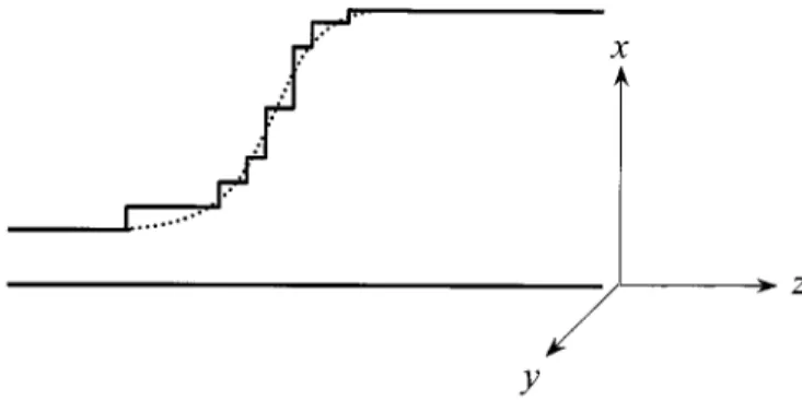
Fig. 2. Staircase approach for the taper transition.
low return-loss and field uniformity of the new structure, we compare the results of taper transitions with and without fins. The conventionally used structure without fins is approximated by the staircase approximation as shown in Fig. 2. It is noted that such a structure may be considered as the degenerate case of the bifurcated discontinuity shown in Fig. 1(b) with dimin-ishing fins.
III. METHOD OFANALYSIS
Returning to Fig. 1, we employ the building-block approach to simplify the analysis of the boundary value problem. First, the input–output relation of the bifurcated PPWG, which is shown in Fig. 3, will be constructed by using a rigorous mode-matching method. Second, the well-known input–output relation of the simple PPWG of finite length is listed for reference. Finally, the field analysis of the cascaded subcells will be conducted.
A. Input–Output Relations of a Bifurcated PPWG
For convenience of discussion, the waveguide treated is a nonuniform two-plate line with infinite extension of the plate in direction. We assume that there is no variation of the structure and the fields along the direction. Therefore, the dependence of the fields is eliminated throughout the deriva-tion. Assuming infinite extension of the plates of a TPL in direction there is obviously no coupling between the upper and lower half and one part can be neglected. In a real TPL, there is a variation of the structure in direction and a coupling between the parts. Furthermore, the variation in direction causes the excitation of higher order TE modes in addition to the set of TM modes.
Referring to Fig. 3, we observe that the transverse fields at the discontinuity consist of the and components, which will be considered explicitly here. The general field solution in each constituent region will be expressed in terms of the superpo-sition of the complete set of PPWG modes. For the transverse components of TM mode in a PPWG region we have
(1a)
(1b)
Fig. 3. The structure of bifurcated PPWG.
where denotes the regions 1, 2, and 3, respectively. Further-more, the longitudinal component in a PPWG region can be given as
(1c)
where is the th TM mode function in a PPWG can be written as
with for
for
(2) and can be interpreted as the voltage and current satisfying the transmission-line equations
(3) (4) where is the propagation wavenumber and
is the characteristic impedance in the direction. At the junction discontinuity , the tangential fields components must be continuous, e.g.,
for
for
(5)
where and are the heights of the semi-infinite PPWG 1 and 3, respectively. Scalar multiplying these equations with and making use of the orthogonality relations, we have
(7)
where is an integer ranging from zero to infinity. Concisely, the last two systems of equations may be written in matrix form
(8) (9) in which the elements of matrices and are the overlap in-tegrals between the two sets of PPWG mode functions and can be written as
(10) (11) It is noted that the superscript over a matrix signifies the “transpose” of the matrix. and are the voltage and current vectors in each region, with and as their th element, respectively. The matrices and are responsible for the coupling among modes in regions 1 and 3 and region 2 and 3, respectively, and will be referred to as the coupling matrices.
Scalar multiplying (5) with and making use of the orthogonality relations and expressing them in the matrix form as described above, we have
(12) similarly, scalar multiplying (5) with and making use of the orthogonality relations and expressing them in the matrix form as described above, we have
(13) Substituting (12) and (13) into (8), we have the unitary condition (14) where is the identity matrix. It is noted that all the matrices and vectors are infinite in order. In practice, the matrices have to be truncated to a finite order for an approximate analysis. The order of truncation is equal to the number of modes retained in the approximate analysis. In general, (14) may be considered as an indicator to see whether the number of modes retained is sufficient.
Returning to Fig. 3, a set of PPWG modes is incident from region 1 while regions 2 and 3 are terminated. In general, the voltage and current vectors for the TM modes in regions 2 and 3 at satisfy the following equations:
(15) (16)
where is the input admittance matrix of the th region. Substituting (15) and (16) into (8) and (9) and making use of the unitary condition (14), we obtain, after some matrix operations, the following equations:
(17) (18) (19) with (20) (21) (22) where is the input admittance matrix of the overall struc-ture. Up to now, the input–output relation of a bifurcated PPWG have been well developed, once the incident PPWG modes are given, the mode amplitudes, which contains TEM and higher order modes in each constituent region can be obtained by (20) and (21).
B. Input–Output Relation of a Uniform PPWG
Consider a PPWG of finite length extending from to . Let the termination condition of this PPWG at be given by
(23) where and are voltage and current vectors for TM modes in the PPWG, with and at their th posi-tions, respectively. is the output admittance matrix looking to the right at . After some manipulations on the solutions of transmission line equations, we obtain
(24)
(25) (26) where is the input admittance matrix looking to the right at , while is the diagonal characteristic admittance matrix. is the transfer matrix which transform the voltage vector from to . Finally, is the reflection matrix at .
C. Input–Output of a Subcell
As described in Section II, the structure of a nonuniform PPWG with fins could be considered as the cascade of basic subcells, each of which consists of a bifurcated PPWG and PPWG of finite length. Since the structure is assumed to be symmetric, we could bisect the original structure into two half-structures; one is terminated by a perfect electric conductor (PEC) and the other is terminated by a perfect magnetic con-ductor (PMC).
HWANG: TRI-PLATE LINE PERFORMANCE USING CORRUGATED TRANSITIONS 317
(a) (b)
(c)
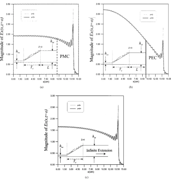
Fig. 4. Continuity of TE fields atz = 0 plane for the case of open circuit; h = 1 cm, h = 15 cm, T = L = 20 cm, frequency is 0.775 GHz, with ten incident PPWG modes. The linear transition is approximated by staircase with 12 steps. (a) Open circuit case. (b) Short circuit case. (c) The case of infinite extension.
It is necessary to determine the reflection of PPWG modes by the overall structure looking to the right at . Moreover, once the reflected mode amplitudes are determined, it is straightfor-ward to determine the electric and magnetic fields in the overall structure. For the reflection of PPWG modes incident from the left in Fig. 1, it is sufficient to have available an input admittance characterization at , to take into account the effects of the cascaded subcells with the termination of a uniform PPWG. The input admittance matrix could be easily evaluated by making use of (20 22) and (24 26) and this constitutes the building-block approach. The input–output relations of the subcells are evalu-ated successively from the output end of the uniform PPWG to the input end of the bifurcated PPWG. Thus, we have available the input admittance matrix denoted by .
TABLE I
CONVERGENCETEST OF THEREFLECTEDPOWERVERSUS ANUMBER OF
(a)
(b)
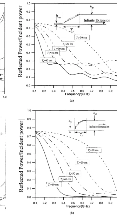
Fig. 5. Variation of reflected power versus frequency for various steps;h = 1 cm, h = 15 cm, T = 20 cm, ten incident PPWG modes. (a) Linear transition. (b) Hypertangent transition.
Returning to the input PPWG at , the voltage and cur-rent vectors are given by
(27) (28)
where is the characteristic admittance matrix in PPWG 1, and are incident- and reflected-voltage vectors, respectively. Since the voltage and current of the input PPWG 1 are related
(a)
(b)
Fig. 6. Effect of reflected power versus frequency with different transition lengths;h = 1 cm, h = 15 cm, ten incident PPWG modes. (a) Linear transition. (b) Hypertangent transition.
by , we have the relationship between incident and re-flected mode amplitudes
(29) (30)
where is the reflection matrix at in the PPWG 1. The infinite summation and matrix dimension derived in the previous sections must be truncated to finite ones. The number of modes in each PPWG regions must be chosen correctly. The
HWANG: TRI-PLATE LINE PERFORMANCE USING CORRUGATED TRANSITIONS 319
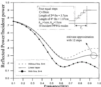
Fig. 7. Comparison of the reflected power versus frequency between linear taper transition and the proposed novel transition with four steps; optimization variables are the fin lengths.
reason is that the height of PPWG determines the propagation constant (and cutoff frequency) of the mode and therefore its amplitude. The amplitude determines whether the mode is nec-essary for the computation at a certain frequency or not. This is known as the problems of relative convergence in the literature. In this paper, we choose the number of modes in each PPWG region in proportion to relative height of the waveguide. How-ever, we have carefully examined the convergence; not only the reflected power, but also the continuity of TE fields across the bifurcated discontinuity to confirm the accuracy of the numer-ical computation.
IV. NUMERICALRESULTS ANDDISCUSSION
Qualitative and quantitative analyses of PPWG modes scat-tered by the conventionally used and the proposed TPL struc-tures can be performed based on the exact formulation described in Section III. Numerical analysis requires not only truncating the infinite system of equations for the Fourier amplitudes to a finite order, but also carefully examining the numerical ac-curacy. After the numerical accuracy is verified, extensive nu-merical data are systematically obtained to identify all possible physical processes associated with the structure under investiga-tion. This investigation describes proposed corrugated transition structure to examine the input impedance and field uniformity in the uniform waveguide of a TPL. In addition, the reflected power of TPL is confirmed with the linear and hypertangent transitions. The proposed transition structures offer a lower re-turn loss and maintain a more uniform electric field behind the transition region than the conventionally used transition struc-ture.
For the field uniformity in a uniform region, the height of a uniform PPWG is limited so that only the TEM mode is sup-ported while all the higher order modes are below cutoff. Thus, during numerical analysis, the heights of uniform PPWGs at two ends of the transition waveguide and , are set to be 1 cm and 15 cm, respectively, while the highest frequency of operation is set to be 1 GHz. On the other hand, according
Fig. 8. Comparison of the reflected power versus frequency between linear taper transition and the proposed novel transition with five steps; optimization variables are the fin lengths.
Fig. 9. Comparison of the reflected power versus frequency between hypertangent taper transition and the proposed novel transition with four steps; optimization variables are the fin lengths and step heights.
to the standard of SAE J1113-23 SEP95, the height of the uniform PPWG where the EUT is placed is set to be 15 cm. Therefore, we use such a parameter to carry out the numerical analysis throughout this investigation. In this work, the stair-case approximation is used to simulate the conventionally used structure. The step discontinuity herein may be viewed as the
(a)
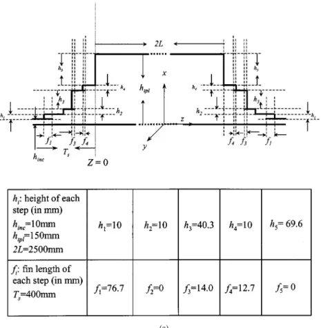
Fig. 10. (a) Structural configuration and geometric parameters for a proposed novel TPL with five steps; optimization variables are the fin lengths and step heights.
degenerate case where the length of PPWG 2 (Fig. 3) dimin-ishes to zero.
The numerical experiment commences with the structures of taper transitions, such as the linear and hypertangent transitions. The convergence of staircase approximation, continuity of TE and reflected power is also carefully examined. In doing so, the reflected power over a range of frequency should be achieved and provides as a valuable reference for comparing with the de-signs proposed herein. Next, the novel transition structure with corrugation is synthesized by applying the optimization algo-rithm to minimize the reflected power over a range of frequency of interest. Our results demonstrate that the low return loss of the proposed designs performs markedly better than that of con-ventionally used structures. Also considered herein is the en-tire TPL structure, including two identical corrugated transitions and a uniform PPWG. Moreover, the same optimization algo-rithm is employed to achieve a design that has a low return loss and high uniformity of electric field in the uniform region. The following sections provide the numerical results and physical explanations.
A. Taper Transition Structures
1) Continuity of TE Field: Accuracy of the numerical
analysis in this work is verified by confirming the field conti-nuity across the interface between the transition and uniform regions. Fig. 4 illustrates the distribution of TE fields at the bifurcated discontinuity for a linear transition approximated by 12 equal steps along the axis. The transition length is 20
cm and the frequency of operation is 0.775 GHz. Three cases with different termination conditions are examined; they are terminated by PMC wall, PEC wall, and infinite extension, as shown in Fig. 4(a)–(c), respectively. According to these figures, the numerical results correlate well with the tangential electric fields across the discontinuity.
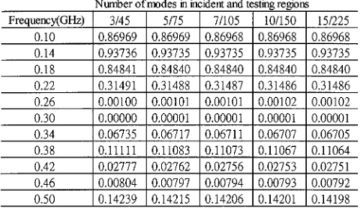
2) Convergence of Reflected Power: After the continuity of
TE fields at the bifurcated discontinuity is verified, the con-vergence of reflected power for various incident PPWG modes is confirmed, indicating the same transition structure as in the previous example. Table I lists the reflected power versus fre-quencies for various incident PPWG modes. The changes in reflected power values generally occur only in the fourth place after the decimal point. According to this table, the conver-gence of reflected power is excellent even for five retained modes. Although we examined the continuity of tangential fields across the bifurcated discontinuities for various incident PPWG modes, those results are not presented herein for brevity. Notably, in this example, the continuity of transverse field can be ensured by taking at least ten modes.
3) Convergence Test for the Staircase Approxima-tion: Herein, the performance of conventionally used structures is compared with that of the proposed one. Notably, the convergence for the number of steps should be carefully examined since the staircase approximation is used to simulate the transition with continuous taper transitions. To achieve the convergence of the staircase approximation, this work examined the reflected power versus frequency for different
HWANG: TRI-PLATE LINE PERFORMANCE USING CORRUGATED TRANSITIONS 321
(b)
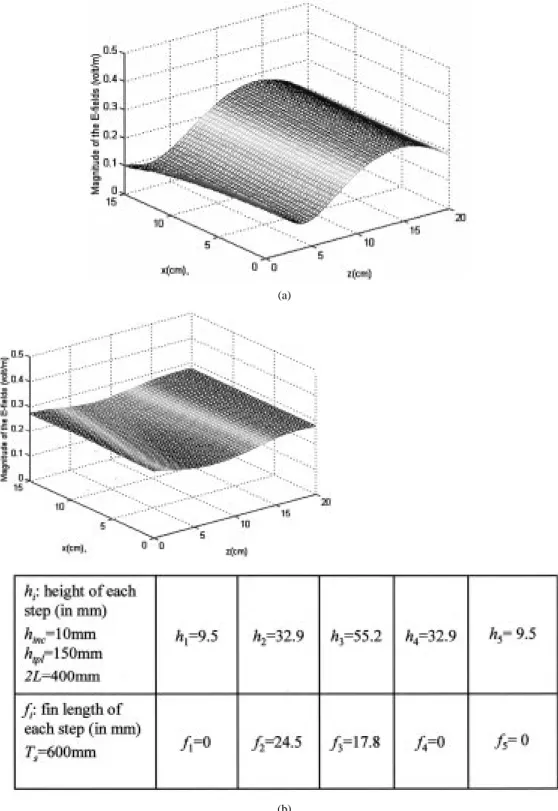
Fig. 10. (Continued.) (b) Continuity of TE fields atz = 0 plane, the structural parameters are the same one as shown in (a).
steps. Fig. 5(a) illustrates the reflected power versus frequency for various equal steps for the case of linear transition. Where the transition length is 20 cm and the number of incident PPWG modes is ten. According to this figure, the results converge to within 99% of each other as long as the number of steps is greater than 12. On the other hand, Fig. 5(b) shows the reflected power versus frequency for various equal steps along axis for the case of hypertangent transition. The transition length and the number of incident PPWG modes are the same as in the case of linear transition. Fig. 5(b) indicates that the results converge to within 97% of each other as long as the number of steps is greater than ten.
4) Effect of Transition Length on the Reflected Power: Fig. 6
displays the variation of the reflected power over a range of the frequency with different transition lengths. Fig. 6(a) summa-rizes the results of the linear transition, while Fig. 6(b) displays those of hypertangent transition. The numbers of steps for the staircase approximation and incident PPWG modes are 12 and 10, respectively. For the long transition length, these figures
re-veal that the slow variation of the height of the PPWG reduces the reflected power. Notably, in the low-frequency range, the re-flection power does not significantly decrease with an increase of the transition length for both types of taper transitions. We can infer that for the low-frequency (long wavelength) range, the re-flection depends mainly on the difference between the heights of and . Therefore, the function of taper transition con-tributes only slightly to the low frequency range.
5) The Proposed Novel Transition Structures: Fig. 7
illus-trates a transition structure of four equal steps shown as an inset. In this numerical example, we take the fin length as a variable and using an optimization algorithm to minimize the reflected power over the range of frequency, in which only the TEM mode is propagating. We have setup a computer program to carry out the simulation. Furthermore, the sum of the error between the computed reflected power and the desired reflected response, over a number of sampling frequencies, is designated as an objective function to be minimized. The algorithm based on Powell’s method [16] is used to find a minimum point of
(c) (d)
Fig. 10. (Continued.) (c) Comparison of the reflected power versus frequency between a conventionally used TPL. The structural parameters are the same one as shown in (a). (d) Distribution of transverse and longitudinal electric field for the novel TPL. The structural parameters are the same one as shown in (a).
the objective function. The optimization process allows us to obtain the fin length of each step, as shown in the inset of Fig. 7. According to this figure, the reflected power is smaller than that of the linear transition case, which is approximated by 12 equal steps and that of the case with four equal steps, but without fins.
In Fig. 8, five equal steps with fins are assumed to be a tran-sition structure. The same optimization process is performed in this example. The fin length of each step is obtained and shown in the inset of Fig. 8. Comparing the reflected power with that of four equal steps in Fig. 7 reveals that the reflected power is low in the high-frequency range.
In the following example, both the heights of steps and the length of fins are taken as variables to minimize the reflected power. The optimization process allows us to obtain the geo-metric parameters to construct a novel structure, which has a lower reflected power than that of a hypertangent transition, as shown in Fig. 9. The transition function after the optimization process reveals the slow variation in the first and last steps of the transition and strong variations with the two steps in the central region. However, the structure appears to closely resemble a hy-pertangent function.
B. TPL with Corrugated Transitions
Until now, this work has synthesized transitions with a lower return loss than conventionally used linear or hyper-tangent ones. Next, a TPL including two identical transitions and a uniform PPWG is considered to investigate the scattering characteristics of guided PPWG modes. The same minimiza-tion algorithm is used to synthesize novel TPL’s having a low return loss from the source and high uniformity of the field distribution in the uniform region. In this numerical experiment, the structural parameters are taken based on [1], i.e., the lengths of transition and uniform PPWG are 40 cm and 250 cm, respectively. The height of the TPL in a uniform
TABLE II
CONVERGENCETEST OF THEREFLECTEDPOWERVERSUS ANUMBER OF
FREQUENCIES FORVARIOUSPPWG MODES ININCIDENT ANDUNIFORM
REGIONS. THESTRUCTURALPARAMETERS ARE THESAMEONE ASSHOWN INFig. 10(a)
region is set to be 15 cm. There are five equal steps along the direction in the transition region. Both the heights of steps and lengths of fins are taken as variables to minimize the reflected power over a frequency ranging from 10 KHz to 500 MHz. The optimization process allows us to obtain a set of variables as shown in Fig. 10(a) to construct a novel TPL.
Verifying the accuracy of the numerical results initially in-volves confirming the continuity of TE fields across the bifur-cated discontinuities. Fig. 10(b) displays the variation of TE fields, over a number of frequencies for various numbers of cident PPWG modes. Evidently, increasing the number of in-cident PPWG modes further improves the continuous of trans-verse fields.
Table II summarizes the reflected power versus frequency for various numbers of PPWG modes in the incident and the uni-form regions, indicating that the convergence is excellent even for the case of three incident PPWG modes. However, achieving
HWANG: TRI-PLATE LINE PERFORMANCE USING CORRUGATED TRANSITIONS 323
(a)
(b)
Fig. 11. (a) Structural configuration and geometric parameters for a proposed novel TPL with four steps; optimization variables are the fin lengths and step heights. (b) Comparison of the reflected power versus frequency between conventionally used TPL and the proposed novel one with four steps; optimization variables are the fin lengths and step heights; ten incident PPWG modes were used for these two cases. The structural parameters are the same one as shown in (a).
a good continuity of TE fields requires taking at least ten inci-dent PPWG modes.
To thoroughly understand the reflection characteristics of the novel structure, a TPL with a conventionally used linear tran-sition is adopted as a reference. Following the convergence test for the number of steps for the staircase approximation, 12 equal steps are used to approximate the linear transitions. Fig. 10(c) reveals that the reflected power of the novel TPL is generally lower than that of conventionally used one, particularly for the frequency is beyond 260 MHz. In the low-frequency range, the
(a)
(b)
Fig. 12. (a) The electric field distribution in the uniform region for the case of conventionally used TPL with linear transition which is approximated by 12 equal steps; the number of incident PPWG modes is ten and the frequency is 0.775 GHz. (b) The electric field distribution in the uniform region for the case of proposed novel TPL. The number of incident PPWG modes is ten and the frequency is 0.775 GHz. The geometric parameters are the same one as shown in Fig. 11(a).
improvement is not obvious as also shown in the examples of transitions structures in Section IV-A.
Fig. 10(d) shows the variation of transverse and longitudinal components of electric fields in the uniform PPWG region. As mentioned earlier in (1c), the higher modes of current waves contribute to the longitudinal electric field component. Since the uniform region supports only one propagating TEM mode, the higher modes decay rapidly from the bifurcated disconti-nuity. The magnitude of obviously decays in the exponential fashion, as shown in Fig. 10(d). Therefore, away from the tran-sition region, the longitudinal component is not obvious. Impor-tantly, reducing the induction of the longitudinal component of an electric field involves placing the EUT away from the transi-tion region. In additransi-tion, the convergence of the results for var-ious incident PPWG modes must also be confirmed. The
con-(a)
(b)
Fig. 13. (a) The electric field distribution in the uniform region for the case of conventionally used TPL with linear transition which is approximated by 12 equal steps; the number of incident PPWG modes is ten and the frequency is 0.703 GHz. (b) The electric field distribution in the uniform region for the case of proposed novel TPL. The geometric parameters are shown in the caption, and the number of incident PPWG modes is ten and the frequency is 0.703 GHz.
vergence is excellent since the curves are converged to the same ones for both components of electric fields.
Fig. 11 displays a linear transition structure of TPL. To realize the reflection characteristics of the novel structure, the heights of steps and the fin lengths are taken as variables and the opti-mization algorithm is used to minimize the reflected power over a frequency ranging from 0.1 to 1.0 GHz. Notably, only the TEM mode is propagating and all the higher modes are below cutoff
in the uniform PPWG. The optimization process allows us to obtain a set of geometric parameters as shown in Fig. 11(a) and a reflected power that is smaller than that of the linear transi-tion case, particularly in the high-frequency range. The periodic variation is caused by the TPL becoming a half-wavelength res-onant.
To understand the field uniformity of the novel structure Figs. 12(a) and 13(a) plot the transverse component of the
HWANG: TRI-PLATE LINE PERFORMANCE USING CORRUGATED TRANSITIONS 325
electric field distribution over the uniform PPWG region for the linear transition structure, while Figs. 12(b) and 13(b) plot that of the proposed structure. The structure proposed herein obviously has a markedly better uniformity than that of conventionally used structures.
V. CONCLUSION
We have presented a novel structure, TPL with fins, for the improvement of the performance of conventionally used one. Through the optimal selection of the structural parameters, it can achieve the low return-loss and maintain a uniform electric field on the transverse plane in the uniform region. Indeed, this offers a new technique for the design of practical TPL.
ACKNOWLEDGMENT
The author would like to thank Prof. S. T. Peng, Chiao-Tung University, Hsinchu, Taiwan, for his encouragement, critical reading of the manuscript, and many suggestions for improve-ment.
REFERENCES
[1] Soc. Automotive Eng. Surface Veh. Recommended Practice, “Electro-magnetic compatibility measurement procedure for vehicle components immunity to radiated electromagnetic fields 10-kHz to 200-MHz Tri-Plate-Line method,”, J113-23, Sept. 1995.
[2] Soc. Automotive Eng. Surface Vehicle Recommended Practice, , “Elec-tromagnetic compatibility measurement procedure for vehicle compo-nents immunity to radiated electromagnetic fields 10-kHz to 500-MHz Tri-Plate-Line method,”, J113-25, Sept. 1996.
[3] J. J. Polonis, W. E. Cory, I. Martinez, D. A. Smith, and H. H. Walker, “Tri-plate test fixture,” in IEEE Int. Symp. Electromagn. Compat., vol. 1, Denver, CO, Aug. 1998, pp. 153–158.
[4] J. D. Robb, et al., “The parallel-plate line for lightning electromagnetic effects testing of electronic systems,” in IEEE Int. Symp. Electromagn.
Compat., Atlanta, GA, June 1978.
[5] S. B. Cohn, “Problems in strip transmission lines,” IRE Trans.
Mi-crowave Theory Tech., vol. 3, no. 2, pp. 119–126, Mar. 1955.
[6] G. Meyer, “A broadband measuring line for the generation of homoge-neous EM-fields,” in Proc. 3rd Symp. Electromagn. Compat., Wrocla, Poland, Sept. 1976, pp. 285–294.
[7] , “Application of a broadband measuring line in field immunity testing,” in Proc. 2nd Symp. Tech. Exhibition .Electromagn. Compat., Montreux, France, 1977.
[8] S. B. Cohn, “Characteristic impedance of shielded-strip transmission line,” Trans. Microwave Theory Tech., vol. 2, pp. 52–57, July 1954. [9] K. G. Blake and T. J. Higgins, “Rigorous determination of the parameters
of strip transmission lines,” IEEE Trans. Microwave Theory Tech., vol. 3, pp. 93–113, Mar. 1995.
[10] M. L. Crawford, “Generation of standard EM fields using TEM transmission cells,” IEEE Trans. Electromagn. Compat., vol. 16, pp. 189–195, Nov. 1974.
[11] J. R. Cummings, “Translational electromagnetic environmental chamber, a new method for measuring radiated susceptibility and emissions,” in IEEE Nat. Symp. Electromagn. Compat., San Antonio, TX, Aug. 1975, pp. 235–238.
[12] R. F. Harrington and J. R. Mautz, “A generalized network formulation for aperture problems,” IEEE Trans. Antennas Propagat., vol. AP-24, pp. 870–873, Nov. 1976.
[13] R. F. Harrington, Time-Harmonic Electromagnetic Fields. New York: McGraw-Hill, 1961, ch. 7.3.
[14] M. Leroy, “On the convergence of numerical results in modal analysis,”
IEEE Trans. Antennas Propagat., vol. AP-31, pp. 655–659, July 1983.
[15] N. Marcuvitz, Waveguide Handbook, ser. MIT Radiation Lab. Ser.. New York: McGraw-Hill, 1951, pp. 179–216.
[16] H. P. Kuenzi, H. G. Tzschach, and C. A. Zehnder, Numerical Methods
of Mathematical Optimization. New York: Academic, 1971.
Ruey Bing Hwang (M’96) was born in Nan-Tou,
Taiwan, on January 20, 1967. He received the B.S. degree in communication engineering from National Chiao-Tung University, Hsinchu, Taiwan, R.O.C., in 1990, the M.S. degree in National Taiwan University in Institute of Electrical Engineering, Taipei, Taiwan, R.O.C., in 1992, and the Ph.D. degree from the Institute of Electronics, National Chiao-Tung University, Hsinchu, Taiwan, R.O.C., in 1996.
From 1996 to 1999, he was with the National Center for High-Performance Computing, in Hsinchu, Taiwan, R.O.C, where he worked on the Computational Electromag-netic. In the summer of 1999, he jointed the Microelectronics and Information Systems Research Center, National Chiao-Tung University, Hsinchu, Taiwan, R.O.C., as an Associated Researcher. In the autumn of 2000, he served as a Research Associated Professor in National Chiao-Tung University, Hsinchu, Taiwan, R.O.C., under the contract of excellent project by the Ministry of Edu-cation. His professional interests include guiding and scattering characteristics of periodic structures, antenna design, and electromagnetic compatibility.