國 立 交 通 大 學
電信工程研究所
碩 士 論 文
人體區域網路之超寬頻天線設計
A Novel UWB Antenna for Wireless Body Area Networks
研 究 生:康鉦浤
指導教授:唐震寰 教授
人體區域網路之超寬頻天線設計
A Novel UWB Antenna for Wireless Body Area Networks
研 究 生:康鉦浤 Student:Cheng-Hung Kang
指導教授:唐震寰 博士 Advisor:Dr. Jenn-Hwan Tarng
國 立 交 通 大 學
電 信 工 程 研 究 所
碩 士 論 文
A Thesis
Submitted to Institute of Communication Engineering College of Electrical Engineering and Computer Engineering
National Chiao-Tung University in Partial Fulfillment of the Requirements
for the Degree of Master
in
Communication Engineering
July 2010
Hsinchu, Taiwan, Republic of China
i Abstract
人體區域網路之超寬頻天線設計
研究生:康鉦浤 指導教授:唐震寰 教授
國立交通大學
電信工程學研究所 碩士班
摘要
人體區域網路,由布置於人體上之無線感知節點所組成的區域網路,感知節點整合 感測電路及無線通訊系統,利用超寬頻無線通訊系統將感測訊號(心跳、血壓、等)傳 達至個人資訊中心,來達成遠端監測的目的。由於無線感測裝置是配戴在人體上,因此 其對天線的需求有 1.天線小且高度低,不干擾人體的日常活動;2.當感知節點放在人體 上時,天線必須避免頻率偏移及輻射場型等特性改變;3.天線場型要減少背向輻射(朝 人體方向),以增加輻射效率及降低人體吸收率(Specific Absorption Rate, SAR)。 本篇論文設計一支可應用在人體區域網路的新型超寬頻天線,其高度為一公分。天線操 作頻寬涵蓋 3.1 GHz ~12 GHz 並且符合上述所有需求。在天線設計中,我們利用斜角 的饋入結構使輸入阻抗緩慢變化來達到寬頻效果。為減低背向輻射,我們設計了一個類 似 patch 天線的輻射體,使天線場型具有指向性且其增益約在 3 dBi~5 dBi。輻射體包 含一個巧妙設計的彎折結構,使操作頻寬符合 10dB 反射損失的需求。本論文也實際量 測天線放在人體上之後的特性,其反射損失幾乎不會受到人體影響。此外我們將肌肉模 型放入模擬軟體中計算人體吸收率(SAR),並與其他平面超寬頻單極天線做比較。 為了避免干擾現存頻譜無線網路(5~6 GHz)系統,我們將彎曲槽線設計在饋入結 構上,使天線反射損失產生帶拒效果,並維持天線原有之特性。我們可以藉由調整槽線 的長度與距離來控制帶拒頻率及頻寬,因此我們將帶拒頻率設計在 5GHz~6GHz 之間, 達到阻絕無線網路干擾的問題。ii
Abstract
A Novel UWB Antenna for Wireless Body Area Networks
Student:Cheng-Hung Kang Advisor:Dr. Jenn-Hwan Tarng
Department of Communication Engineering
National Chiao Tung University
Abstract
Wireless Body Area Network (WBAN) is wireless sensor network which is applicable on the human body. The sensors, which are applied on the human body, transmit the
wanted/desired signal to the center devices for remote monitoring. The sensor devices are placed on the human body so there are three requirements for the antenna (which is integrated with the sensor device): 1. Compact form and low height: The antenna should be unobtrusive when it is placed on the human body in order to avoid interfering in the human‟s daily
activities. 2. Low mutual effect between the antennas and the human body: The antenna should keep the characteristics such as operating bandwidth when applying to the body. 3. Low backward (direction to the human body) radiation: In order to decrease the Specific Absorption Rate and increase the radiation efficiency. Owing to these three restrictions on antenna characteristic, designing an UWB antenna for WBAN is a challenge. In this thesis, we propose a novel patch-like UWB antenna used in WBAN application. The proposed antenna consists of a bevel edge fed structure and a truncated radiator. The bevel edge of the fed structure is designed for slow impedance variation and achieves very wide bandwidth. The patch-like radiator is designed for reducing the backward radiation and results in the directional radiation patterns. Moreover, the folded strip of the radiator is a key factor in
iii
Abstract
antenna design, it affect the impedance match of the desired bandwidth. By suitable designing the folded strip, the return loss is over 10dB condition within the operating bandwidth. In this thesis, we also compare the measured return losses of the proposed antenna in free space and on the human body. In order to obtain the SAR values, the muscle models are employed in simulation.
In order to avoid interfering the existent wireless application such as WLAN, a meander slit, a band-stop resonator, is designed at the fed structure of the proposed UWB antenna. The additional slit creates the band-rejected property while keeping the other characteristics almost the same. We can control the notch property including frequency and bandwidth by adjusting the length and distance of the slit. In final design, the band-rejected property is designed in 5GHz ~ 6GHz to prevent the interference from the WLAN.
iv Acknowledgement
Acknowledgement
在碩士兩年的研究生涯中,我最要感謝的就是指導教授 唐震寰教授並在此致上最 真誠的謝意。感謝老師在我的研究生涯中,給于我在電信與電波專業領域的指導,讓我 在碩士生涯中獲益良多,也感謝老師提供實驗室豐富的資源與良好的環境,讓我們能夠 在完備的環境中研究與實驗,並順利完成本篇碩士論文。同時感謝口試委員:彭松村教 授、楊成發教授、林丁丙教授給予我論文上的建議與指導,讓我知道其中的不足與改進 之處,讓此篇論文更加完整。 再來,要感謝實驗是學長們:松融學長、文崇學長、雅仲學長、俊諺學長、明宗學 長、廣琪學長、振民學長、兆凱學長,感謝他們給於我專業領域上的指導與建議,解決 我研究的疑惑與徬徨。另外感謝實驗室所有成員:耿賢、冠豪、國政、昌喆、佳迪、舜 哥,無論一起討論作業、一起打球、一起歡樂聚餐,讓實驗室不單只有嚴肅的研究,更 添加了歡樂與多彩,豐富了我兩年的研究所生活。同時,也要感謝助理梁小姐,感謝他 對於我們儀器及設備採購的協助,及大小瑣事的幫忙。 最後要感謝的是我的心愛的家人,感謝弟弟,陪我打屁聊天,紓解我研究的緊繃心 情。最要感謝爸爸媽媽提供我舒適無缺的生活環境,給我最真誠的關懷與鼓勵,讓我有 最幸福的人生,可以毫無後顧之憂的專心研究與念書。僅以此篇論文獻給我最至愛的爸 媽及家人。 康鉦浤 致予 九十九年七月 交大工四 902v Contents
Contents
Abstract(Chinese) ... i
Abstract(English) ... ii
Acknowledgement ... iv
Contents ... v
List of figure ... vii
List of Table ... ix
Chapter 1 - Introduction ... 1
1-1 Background ... 1
1-2 Related Works and Motivations ... 3
1-3 Thesis Organization ... 5
Chapter 2 – Introduction of Broadband Antennas ... 6
2-1 Biconical Antenna ... 6
2-2 Traveling-wave Antenna ... 11
2-3 UWB Antenna Review... 13
2-3-1 A Disc Monopole Antenna ... 13
vi
Contents
Chapter 3 – The Proposed Directional UWB Antenna... 16
3-1 Design Concept ... 16
3-2 The proposed UWB antenna ... 17
3-3 Radiation Patterns ... 24
3-4 Proximity Effect of Human Body and SAR Values ... 24
Chapter 4 – The Proposed UWB BAN Antenna with Band-Rejected
Property ... 29
4-1 Motivation and Design Concept ... 29
4-2 The proposed band-rejected UWB antenna ... 32
4-3 Radiation Patterns and on body transmission ... 37
Chapter 5 – Conclusion ... 40
vii
Contents
List of figure
Fig. 1.1 The schematic of Body Area Network ... 2
Fig. 2.1 Biconical antenna geometry. ... 7
Fig. 2.2 (a) Electric and magnetic fields for a biconical antenna. (b) Associated voltages and currents for a biconical antenna. ... 7
Fig. 2.3 Measured input impedance of a conical monopole with flare angle versus monopole height Lh. ... 10
Fig. 2.4 Traveling wave long wire antenna. ... 11
Fig. 2.5 Pattern of a traveling wave long wire antenna. (L=6λ) ... 12
Fig. 2.6 The geometry of the circle disc monopole antenna... 13
Fig. 2.7 The measured return loss of the circle disc monopole antenna. ... 14
Fig. 2.8 The geometry of the planar UWB monopole antenna and its S11. ... 15
Fig. 3.1 The structure of the proposed antenna. ... 17
Fig. 3.2 The simulated and measured return loss of the proposed antenna. ... 18
Fig. 3.3 The simulated input impedance of the proposed antenna. ... 18
Fig. 3.4 The simulated return losses of the proposed antenna with various length of H1. ... 19
Fig. 3.5 The simulated return losses of the proposed antenna with and without the folded strip. ... 20
Fig. 3.6 The simulated return losses of the proposed antenna with various length of L3. ... 21
Fig. 3.7 The simulated return losses of the proposed antenna with various length of L4. ... 23
viii
Contents
Fig. 3.9 The radiation patterns of the proposed antenna (a) at 4GHz (b) at 7GHz (c) at 10GHz ... 25 Fig. 3.10 The measured return losses of the proposed antenna in free space and on the body.28 Fig. 3.11 The simulated return losses of the general planar disc monopole antenna. ... 28 Fig. 4.1 The simulated and measured S-parameter of a micro-strip with U-shaped slit on the
ground. ... 30 Fig. 4.2 The simulated and measured S-parameter of a micro-strip with U-shaped slit on the line. ... 31 Fig. 4.3 The structure of the proposed band-rejected UWB antenna. ... 32 Fig. 4.4 The photograph of a real fabricated band-rejected UWB antenna. (a) Unbent in to a plate (b) The antenna mounted on the ground plane. ... 33 Fig. 4.5 The simulated return losses of the proposed band-rejected UWB antenna... 33 Fig. 4.6 The simulated input impedance of the proposed band-rejected UWB antenna. ... 34 Fig. 4.7 The current distribution of the proposed antenna (a) at 4GHz (b) at 5.6GHz (c) at 7 GHz (d) at 10GHz. ... 35 Fig. 4.8 The simulated return losses of the proposed band-rejected antenna with various length of W5 ... 36
Fig. 4.9 The simulated return losses of the proposed band-rejected antenna with various length of W4 ... 37
Fig. 4.10 The simulated radiation patterns of the proposed band-rejected UWB antenna (a) at 4 GHz (b) at 7 GHz (c) at 10GHz ... 38 Fig. 4.11 The environment settings of measuring the on body transmission. ... 39 Fig. 4.12 The measured S21 of the proposed band-rejected antenna placing on the body. ... 39
ix
Contents
List of Table
TABLE 1.1 Summarize the related UWB antennas used in BAN ... 4 TABLE 3.1 Peak SAR values and radiation efficiency (Rad. Eff.) of the proposed UWB
antenna and planar disc monopole antenna with three layers muscle model .... 27 TABLE 3.2 Peak SAR values and radiation efficiency (Rad. Eff.) of the proposed UWB
1
Chapter 1 Introduction
Chapter 1 -
Introduction
1-1 Background
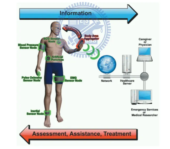
Wireless Body Area Network (WBAN) is wireless communication systems which transmit information and data near the human bodies. In WBAN, some proper devices and sensors are applied to human body and everyday clothing for short range communication and monitoring the human health. In other words, the WBAN sensors can supervise the vital signs of patients, police, or fire personnel, and then send the data to a center device for remote monitoring [1] as shown in figure 1.1. Moreover, the police, fire personnel and military can also employ the WBAN system for short range communication within the group. Since the Body Area Network communication system can be applicable in various environments and purpose, the topic becomes an active and worth research.
With increasing attention toward WBAN, the ultra-wideband (UWB) technology is an attractive solution for WBAN applications because of its low transmiting power and high data
2
Chapter 1 Introduction
rates. The IEEE 802.15.4a task group [2], who has developed an ultra-wideband (UWB) standard regarding Physical and Media Access Control layer, involves the body area network as a relevant scenario. In 2002, the Federal Communication Commission (FCC) had also allocated the spectrum from 3.1 GHz to 10.6 GHz for UWB unlicensed applications.
For Body Area Network, the antenna is placed on the human body for transmission so the application confines to the antenna design. The antenna should be unobtrusive and conformal in order to avoid interfering in the human‟s daily activities. Furthermore, the antenna performance such as bandwidth and radiation patterns could be interfered after placing on the human body. The Specific Absorption Rate can be also an issue which should
3
Chapter 1 Introduction
be considered in antenna design. Owing to these restrictions on antenna characteristics, designing the UWB antennas used in BAN is a challenge and a worth topic.
1-2 Related Works and Motivations
In past few years, there have been various works [3, 4] which discuss the channel model of UWB system near the human body and compare the measured results of different antennas. In [3], the UWB channels were measured from 3 GHz to 6 GHz for Body Area Network in anechoic chamber and an office room. The measured delay spread and mean excess delay are shown that the multi-path components are obvious in office environments compare to in anechoic chamber. Moreover, the path loss was calculated from transfer functions, the results reveal that the path loss is highly relative to the position of antennas on body. In [4], it
compares the on body measurements of two different antennas. One is the 3-D planar inverted cone monopole antenna (PICA) where the antenna is perpendicular to the human body, and the other is a printed horn shaped self-complementary antenna (HSCA). The measured results shows that the 3-D PICA represents lower path loss compare to the ones of HSCA. However, the PICA radiator is perpendicular to the human body so that the antenna is impractical when applied to the human body.
Several studies provide various antenna designs used in WBAN [4-10]. Planar monopole antennas with compact form and low height are widely developed in UWB community.
However, the operating bandwidth and radiation characteristics are easily affected by the body when the planar antennas are placed on the human body directly [5]. The Specific Absorption Rate is also a problem because of its omni-directional patterns. In [7], the simulation results show that the omni-directional antenna exhibits low radiation efficiency and high SAR values compared to the directional antenna when placed on the muscle model.
4
Chapter 1 Introduction
Compact profile, Low backward radiation, and low mutual effect between the antenna and the human body are three major requirements [7-10] for WBAN antennas. These features increase the difficulty of antenna design. To solve this issue, some studies propose using a reflector in antenna design to reduce the backward radiation and enhance directionality. In [7], a reflector was added to a slot antenna whose bandwidth is from 3GHz to 6GHz. By using this additional reflector, it can enhance the antenna directionality and reduce the backward
radiation. But the additional reflector affects the antenna bandwidth which becomes 4GHz to 6.5GHz.
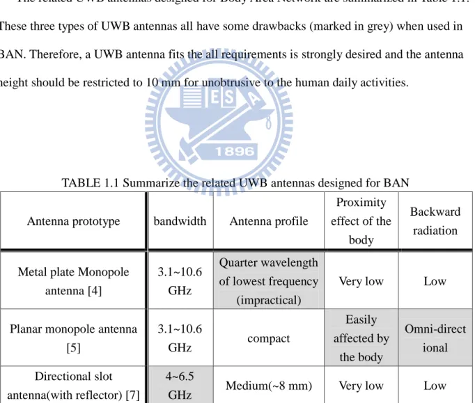
The related UWB antennas designed for Body Area Network are summarized in Table 1.1. These three types of UWB antennas all have some drawbacks (marked in grey) when used in BAN. Therefore, a UWB antenna fits the all requirements is strongly desired and the antenna height should be restricted to 10 mm for unobtrusive to the human daily activities.
TABLE 1.1 Summarize the related UWB antennas designed for BAN
Antenna prototype bandwidth Antenna profile
Proximity effect of the
body
Backward radiation
Metal plate Monopole antenna [4] 3.1~10.6 GHz Quarter wavelength of lowest frequency (impractical)
Very low Low
Planar monopole antenna [5] 3.1~10.6 GHz compact Easily affected by the body Omni-direct ional Directional slot antenna(with reflector) [7] 4~6.5
5
Chapter 1 Introduction
1-3 Thesis Organization
This thesis comprises five chapters including the introduction. Chapter 2 introduces the basic theory of the broadband antennas and some UWB antenna prototype. The proposed UWB antenna and its design concept are discussed in chapter 3, and some parametric studies are shown in this chapter to validate the radiation mechanism. The simulated SAR values of the proposed antenna are also compared with omni-directional antenna in chapter 3. Chapter 4 represents the proposed UWB antenna with band-rejected property and we also discuss the design guideline of the band-rejected mechanism. Chapter 5 draws the conclusion of this thesis.
6
Chapter 2 The basic theory of broadband antenna
Chapter 2 –
Introduction of Broadband Antennas
2-1 Biconical Antenna
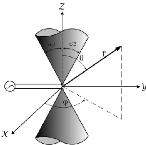
A simple broadband antenna which evolved from the dipole antenna is the biconical antenna. The biconical antenna is formed by two infinite extent cone as shown in figure 2.1, and the antenna can be thought to represent a tapered transmission line. We can calculate the radiated field and input impedance by analyzing the current and field distribution. The applied voltage Vi at the input terminal will generate the current I along the surface of the cone and
voltage V between the cones, as shown in figure 2.2(a). The voltage and current cause the electromagnetic wave, shown in figure 2.2(b). We assume that the dominant TEM mode (E and H are transverse to the direction of propagation) is excited. From faraday‟s law, we can obtain
7
Chapter 2 The basic theory of broadband antenna
Fig. 2.1 Biconical antenna geometry.
Fig. 2.2 (a) Electric and magnetic fields for a biconical antenna. (b) Associated voltages and currents for a biconical antenna.
Which can be expanded in spherical coordinate and assumed that there is only Eθ component independent of φ. Therefore, the above equation can be reduced to
∇ × E = −jωH
(2-1)
8
Chapter 2 The basic theory of broadband antenna
It is necessary to form the TEM mode with Eθ so the H only has a Hφ, and then equation
(2-2) can be written as
From Ampere‟s law, we can write that
which can be expanded in spherical coordinate and assumed only Eθ and Hφ component
independent of φ, and the equation can be reduced to
We substitute (2-6) into (2-3), and it form a different equation for Hφ as
A solution, which meets the condition of (2-5) , (2-7) and represents an outward traveling wave, is
Since the field is TEM mode, the electric field is related to the magnetic field by intrinsic impedance, and we can write is as
Eθ = ηHφ = η H0 sin θ e−jkr r Hφ = H0 sin θ e−jkr r ∂2 ∂r2 rHφ = −ω2μϵ rHφ = −k2(rHφ) ∂ ∂θ r sin θ Hφ = 0 1 r sin θ ∂ ∂r r sin θ Hφ = 1 r ∂ ∂r(rHφ) = −jωϵEθ ∇ × H = +jωϵE 1 r ∂ ∂r rEθ = −jωμHφ ∇ × E = a φ1 r ∂ ∂r rEθ = −jωμ(a rHr + a θHθ+ a φHφ) (2-2) (2-3) (2-4) (2-5) (2-6) (2-7) (2-8) (2-9)
9
Chapter 2 The basic theory of broadband antenna
The voltage which is produced between two corresponding points on the cones, a distance r from the origin, can be found by
Where α is the cone angle. We can substitute (2-9) into (2-10) to obtain
Moreover, the surface current of the cones, a distance r from the origin, can be found as follows
The voltage and current at a distance r from the origin can be observed in figure 2.2. We can use the voltage of (2-11) and the current of (2-12) to calculate the characteristic impedance as
The input impedance is real because the structure is infinite. If the length of biconical is finite, the discontinuities will cause reflections setting up standing waves, which would show up as a reactive component in the impedance.
The finite biconical antenna is practical in realization. The TEM waves exist with high-order modes created at the ends of the cones, and the high-order modes contribute mainly to the antenna reactance. The reactive part of the input impedance can be held to a minimum over a progressively wider bandwidth by increasing the angle α, and in this way, the real part of the input impedance becomes insensitive to different frequency. The phenomenon is illustrated in figure 2.3, which shows the measured impedance of different angle conical
Zc = V(r) I(r) = η πln cot( α 4) I r = Hφrsinθdφ 2π 0 = H0e−jkr dφ 2π 0 = 2πH0e−jkr V r = ηH0e−jkr dθ sinθ π−α 2 α 2 = ηH0e−jkr ln cot(α/4) tan(α/4) = 2ηH0e −jkr ln cotα 4 V r = π−α 2E ∙ dl α 2 = a θEθ ∙ (a θrdθ) π−α 2 α 2 = Eθrdθ π−α 2 α 2 (2-10) (2-11) (2-12) (2-13)
10
Chapter 2 The basic theory of broadband antenna
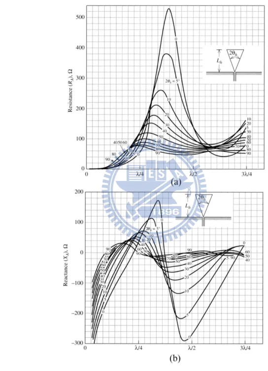
Fig. 2.3 Measured input impedance of a conical monopole with flare angle versus monopole height Lh.
monopole antenna versus the height Lh. This figure clearly shows that the conical monopole
antenna with wider cone angle can easily achieve 2:1 impedance bandwidth, which is one of the definitions of a broadband antenna.
11
Chapter 2 The basic theory of broadband antenna
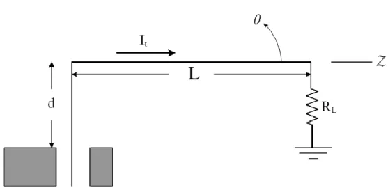
Fig. 2.4 Traveling wave long wire antenna.
2-2 Traveling-wave Antenna
In general case, the wire antenna we have discussed is resonant structure. The wave which travels from the feed point to the end of the wire is reflected, setting up a standing wave current. For example, the current for the top half of the dipole can be written as
The first term in brackets is taken to represent an outward traveling wave while the second term is a reflected wave. However, if there is no apparently reflected wave on an antenna, it is referred to as a traveling wave antenna. A traveling wave antenna is like a guiding structure for traveling waves and it can be created by using matched loads at the ends to prevent reflections. The simplest traveling wave wire antenna is a straight wire carrying a pure traveling wave. The traveling long wire, which is greater than one-half wavelength long, is shown in figure 2.3. In the figure, the long wire is shown being fed from a coaxial
transmission line and with a matched load RL to prevent reflection from the wire end. The
radiation pattern of a long wire can be shown as Imsin β L 2− Z = Im 2je j βL2 e−jβz − ejβz (2-14)
12
Chapter 2 The basic theory of broadband antenna
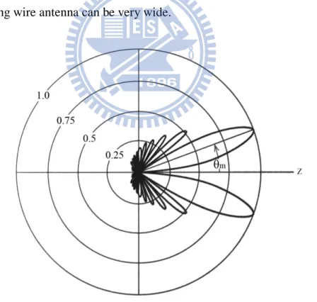
Fig. 2.5 Pattern of a traveling wave long wire antenna. (L=6λ)
where K is a normalization constant that depends on the length L. The polar pattern for L=6λ is drawn in figure 2.4, which shows the main beam is a rotationally symmetric cone about the z-axis.
The input impedance of a traveling-wave antenna is almost real. By recalling the impedance of a pure traveling wave on a low-loss transmission line is equal to the characteristics impedance (real) of the transmission line. Antennas that support traveling waves operate in a similar manner. The termination resistance should equal the value of the radiation resistance. The radiation resistance of a traveling long wire antenna is 200 to 300Ω. Since the termination resistance is always independent of frequency, the bandwidth of a well-matched long wire antenna can be very wide.
F θ = K sin θsin[(βL 2 )(1 − cosθ)] βL 2 (1 − cosθ)
(2-15)
13
Chapter 2 The basic theory of broadband antenna
Fig. 2.6 The geometry of the circle disc monopole antenna.
2-3 UWB Antenna Review
In previous section, we have introduced the prototype of the wide-band antennas and its basic analyzing. In order to further understand the operating mechanism of the UWB antenna, two kinds of UWB antenna is reviewed and discussed in this section.
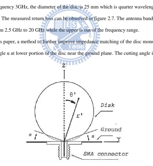
2-3-1 A Disc Monopole Antenna
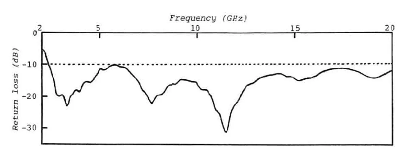
The most common UWB antenna is various shaped metal plate monopole antenna which is modified from wire monopole antennas. In [13], a disc metal plate fabricated on 0.5 mm copper is mounted on a 300×300 mm2 ground plane as shown in figure 2.6. In order to design lowest frequency 3GHz, the diameter of the disc is 25 mm which is quarter wavelength at this frequency. The measured return loss can be observed in figure 2.7. The antenna bandwidth covers from 2.5 GHz to 20 GHz while the upper is out of the frequency range.
In this paper, a method to further improve impedance matching of the disc monopole is cutting angle α at lower portion of the disc near the ground plane. The cutting angle is
14
Chapter 2 The basic theory of broadband antenna
Fig. 2.7 The measured return loss of the circle disc monopole antenna.
removing stray capacitance between the disc and the ground plane, so the impedance matching can be improved. For cutting angle α=20∘, the return loss less than -15dB is obtained at least from 2.5 GHz to 12 GHz.
In addition to the circular disc monopole antenna, the elliptical disc monopole can be also an UWB antenna. In [14], different ellipticity ratios disc antenna are compared and discussed. It concludes that the disc antenna with ellipticity ratio equal to 1.1 has the maximum bandwidth (bandwidth ratio 1:10.7), and the bandwidth decrease as the ratio becomes to 1.4. The lowest operating frequency of these antennas can be predicted by the equation
where L is the antenna length, and r is equivalent radius obtained by 2πrL = πab (a and b are the semi-major axis and the semi-minor axis respectively), the all units are in mm. Moreover, the square, rectangular and hexagonal shapes monopole antennas represent rather narrow bandwidth compared to the disc monopole antenna, which is also validated in [14].
The radiation patterns of the disc monopole antenna are similar to the vertical linear monopole antenna where the E plane is conical shaped and the H plane is omni-directional.
f =c λ= 3 ∗ 1011 (L + r) 0.24 (2-16)
15
Chapter 2 The basic theory of broadband antenna
Fig. 2.8 The geometry of the planar UWB monopole antenna and its S11.
2-3-2 planar monopole UWB antenna
The general UWB monopole can be further expanded to a planar one. The planar
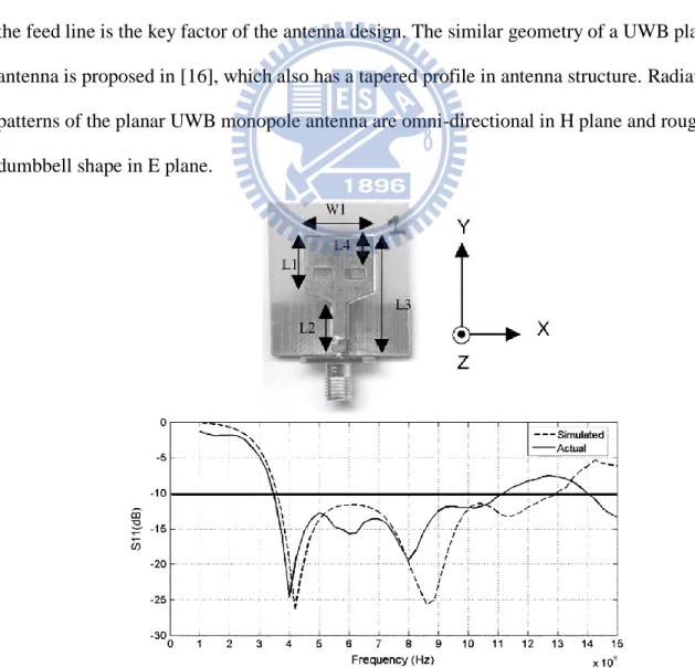
monopole UWB antenna is fabricated on a Printed Circuit Board with micro-strip feed line. In [15], three methods are applied for good impedance matching of planar UWB monopole antenna: 1. Tapered connection between the rectangular patch and the feed line. 2. The dual slots on the patch. 3. A partial ground plane flushed with feed line. According to the paper, the geometry parameters of the three structures can be adjusted to tune the return loss over wide range of frequency. The final geometry of the planar UWB monopole antenna and its return loss are shown in figure 2.8. It is noted the tapered connection between rectangular patch and the feed line is the key factor of the antenna design. The similar geometry of a UWB planar antenna is proposed in [16], which also has a tapered profile in antenna structure. Radiation patterns of the planar UWB monopole antenna are omni-directional in H plane and roughly dumbbell shape in E plane.
16
Chapter 3 The proposed directional UWB antenna
Chapter 3 –
The Proposed Directional UWB Antenna
3-1 Design Concept
There are two general ways to design wideband antennas, one is to create
multiple-resonant current paths and combine the resonant frequencies to achieve wideband operation. The yagi-Uda antenna and log-periodic antenna are two kinds of antenna using the multiple-resonant method. The other way is to utilize the traveling wave concept or tapered profile to attain slow input impedance variation, which means a very wide operating
bandwidth can be obtained. The proposed antenna in this thesis uses the tapered profile on the feed structure to achieve very wide bandwidth which involves the UWB band.
The directional patterns result in the low backward radiation and low proximity effects of human body as well as SAR values. Because the antenna is placed on the human body, the directional pattern is desired to reduce the backward radiation and SAR values. Antenna directionality is usually resulted from a stacked structure or a directors-built structure. The
17
Chapter 3 The proposed directional UWB antenna
general patch antenna is a stacked structure and represents directional radiation patterns. In order to perform directionality, the patch style radiator is included in our antenna design.
3-2 The proposed UWB antenna
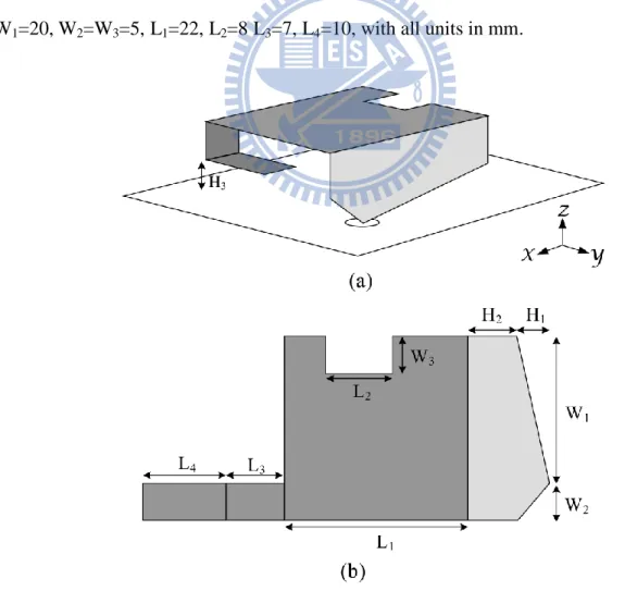
The proposed antenna consists of a bevel-edge feed structure, and a truncated plate with a folded strip as shown in figure 3.1, where the bevel-edge structure is colored in light grey and the radiator is colored in dark grey. The whole antenna is mounted on a 50*50 mm2 ground plane. Moreover, the proposed antenna can be unbent into a plate for easy fabrication as shown in figure 3.1(b). Full dimensions of the proposed antennas are H1=4, H2=6, H3=3,
W1=20, W2=W3=5, L1=22, L2=8 L3=7, L4=10, with all units in mm.
18
Chapter 3 The proposed directional UWB antenna
Fig. 3.2 The simulated and measured return loss of the proposed antenna.
19
Chapter 3 The proposed directional UWB antenna
Fig. 3.4 The simulated return losses of the proposed antenna with various length of H1.
Figure 3.2 shows the simulated and measured return losses of the proposed antenna while the simulation is performed by Ansoft HFSS and measurements are taken by E8364B network analyzer. The measured results agree with the simulated ones; some minor
discrepancies can be attributed to the fabrication tolerance. The operating bandwidth of the proposed antenna covers from 3.1GHz to 12GHz under 10dB return loss condition according to the figure. In the antenna design, the bevel edge of the feed structure is designed for slow impedance variation, which can be validated in figure 3.3. Figure 3.3 shows the real and imaginary impedance of the proposed antenna, the impedance of the proposed antenna from 6GHz becomes steady with real part and imaginary part are nearly 40Ω and 0Ω respectively. This is the key factor that why the proposed antenna can achieve ultra-wide bandwidth.
20
Chapter 3 The proposed directional UWB antenna
Fig. 3.5 The simulated return losses of the proposed antenna with and without the folded strip.
signal. Therefore, the length of the feed structure edge ( H12+ W12+ H2) should be quarter
wavelength of the lowest frequency for better impedance matching. In order to reduce the antenna size, the original symmetrical feed structure was evolved into an unsymmetrical one.
Moreover, the slope of the tapered profile can influence the antenna performance. From figure 3.4, we can observe that the different H1 which means that the different slope of the
feed structure affects the antenna impedance match. Acting as a feed structure of the whole antenna, the length of H1 also determines the impedance match in low frequency. By suitably
choosing the length of H1, the best impedance matching can be obtained.
The plate radiator is like a patch antenna whose length of the edge is almost half
21
Chapter 3 The proposed directional UWB antenna
Fig. 3.6 The simulated return losses of the proposed antenna with various length of L3.
half-wavelength of the mid-resonant frequency. For reducing the size of the radiator, the truncated edge is designed in the radiator. Moreover, an unbalance folded strip is designed in the radiator for extending the current path in lowest frequency and obtaining the better
impedance match in lower frequency. The folded strip not only extends the equivalent current path in low frequency but also provides additional capacitance to create better impedance match.
The truncated plate with folded strip is the main radiator. The folded strip of the radiator is a key factor of antenna design; it not only determines the lowest operating frequency but also creates additional resonant frequency around 6GHz. Figure 3.5 shows the comparison of the return loss between the proposed antenna with and without the folded strip. It can be observed that the proposed antenna without the folded strip performs the lowest frequency at
22
Chapter 3 The proposed directional UWB antenna
4 GHz and presents impedance mismatch at 6 GHz. However, after adding the folded strip to the proposed antenna, the lowest frequency shifts from 4 GHz to 3.1GHz and an additional resonant frequency around 6 GHz is created.
We further discuss the influence of the folded strip by comparing the simulated return loss in different lengths, L3 and L4. The simulated return losses of the proposed antenna with
various lengths L3 are shown in figure 3.6. Figure 3.6 indicates that the lowest frequency
shifts from 3 GHz to 3.7 GHz as the length of L3 changes from 3mm to 9mm. The length of
L3 determines the lowest operating frequency but the impedance becomes mismatch when the
L3 exceeds 9mm. Moreover, figure 3.7 shows the simulated return losses of the proposed
antenna with various lengths L4 where its length changes the mid resonant frequency from
6.28 GHz to 5.09 GHz. In order to cover the UWB bandwidth, L3 and L4 are designed with
length of 7 mm and 10 mm respectively.
Since the radiator is like a patch antenna, the length of the radiator affects the resonance at 4.5 GHz. For this reason, the truncated part of the radiator is designed to miniature the antenna size. Figure 3.8 shows the return losses of the proposed antenna with various widths of the truncate edge W3. The figure exhibits that the longer W3 the lower resonant frequency it
23
Chapter 3 The proposed directional UWB antenna
Fig. 3.8 The simulated return losses of the proposed antenna with various length of W3.
24
Chapter 3 The proposed directional UWB antenna
3-3 Radiation Patterns
The radiation patterns of the proposed antenna is simulated and measured in 4GHz, 7GHz and 10GHz as shown in figure 3.9. The measurements agree with the simulation results. The patterns represent directionality with low backward radiation because of the patch-like structure. In xz-plane, the radiation patterns show directionality with peak gain values 5.8dBi, 5.2dBi and 3dBi for each frequency. In yz-plane, the patterns are also nearly directional in every frequency and the peak gain values are 4.2dBi, 7.2dBi and 4.8dBi for 4GHz, 7GHz and 10GHz. Moreover, the power levels of backward radiation are less than -5dBi for each
frequency. It is evident that the proposed antenna is desired in WBAN application for low backward radiation.
3-4 Proximity Effect of Human Body and SAR Values
In WBAN application, the antenna is mounted on the human body. It is known that the human body has some impact on the antenna characteristics such as input impedance and radiation patterns. Therefore, it is important to verify if the proposed antenna is suitable for placing on the human body. The measured return losses of the proposed antenna in free space and on the body are compared in this section. Furthermore, the truncated human model is involved in simulation to estimate the Specific Absorption Rate value and radiation efficiency.
Figure 3.10 shows the comparison measured return losses of the proposed antenna in free space and on the body. The antenna is placed on the body directly with 2mm space between the antenna and the body. The proximity effect of the human body only slightly affects the impedance match of the proposed antenna instead of diminishing the operating bandwidth. The mutual effect between the antenna and the human body is very low because the ground plane is designed between the radiator and the human body.
25
Chapter 3 The proposed directional UWB antenna
Fig. 3.9 The radiation patterns of the proposed antenna (a) at 4GHz (b) at 7GHz (c) at 10GHz
26
Chapter 3 The proposed directional UWB antenna
Two types of truncated body models are employed to EM simulation according to [7]. The first one is a three-tissue model, including skin (1 mm), fat (3 mm) and muscle (40 mm), and the other is only a muscle tissue (44 mm). The entire dimensions of the model are
120*110*44 mm3. Through the author‟s experience of [7], the model size is tested and found by comparing the simulated results of larger model. There are no significant differences between the proposed size and the larger size so the final size is used for simulation efficiency.
In this thesis, the proposed antenna and a general UWB planar monopole antenna which has omni-directional patterns are simulated with the body model for SAR values and radiation efficiency. The antenna structure and return loss of the general UWB planar monopole
antenna are shown in figure 3.11. This general UWB planar monopole antenna is a disc shape planar antenna fabricated on 0.77mm substrate with εr=3.3. It is noted that in the simulation,
the proposed antenna is placed 2 mm away from the body model while the general UWB planar antenna is 10 mm away from the body model. By doing this, the two antennas represent almost the same height from the top of the antenna to the body model. Table 3.1 shows the simulation results of average 10g peak SAR value and radiation efficiency of the antennas with one layer muscle model. The SAR values of the proposed antenna at 4GHz, 7GHz and 9GHz are 1.076, 1.518 and 3.22 respectively while the values of the disc planar monopole antenna are 7.48, 3.93 and 2.57. It is noted that the proposed antenna has lower SAR values and high radiation efficiency at 4GHz and 7GHz compared to the disc planar monopole antenna whereas the SAR values are higher than the disc planar monopole at 9GHz. The reason is that the radiate power is decreased with increasing the electrical distance
(related to frequency). Therefore, the 10mm between the disc monopole antenna and the muscle is longer for 9GHz compared to 4GHz and 7GHz so the muscle absorbs less power at high frequency.
27
Chapter 3 The proposed directional UWB antenna
three layer muscle model at 4GHz and 7GHz. The results show that the proposed UWB antenna is better than the planar disc monopole antenna. From these results, it can be also validated that the directional antennas with low SAR values is much desired than the omni-directional antennas when used in BAN.
TABLE 3.1 Peak SAR values and radiation efficiency (Rad. Eff.) of the proposed UWB antenna and planar disc monopole antenna with one layer muscle model
Proposed UWB antenna Planar Disc Monopole antenna
SAR【W/kg】 Rad. Eff.【%】 SAR【W/kg】 Rad. Eff.【%】
4 GHz 1.076 88.72% 7.48 64.35%
7 GHz 1.518 80.24% 3.93 79%
9 GHz 3.22 78.5% 2.57 83.65%
(Pin=1W)
TABLE 3.1 Peak SAR values and radiation efficiency (Rad. Eff.) of the proposed UWB antenna and planar disc monopole antenna with three layers muscle model
Proposed UWB antenna Planar Disc Monopole antenna
SAR【W/kg】 Rad. Eff.【%】 SAR【W/kg】 Rad. Eff.【%】
4 GHz 1.41 85.64% 11.2 40.63%
7 GHz 1.735 84.67% 4.99 80.17%
28
Chapter 3 The proposed directional UWB antenna
Fig. 3.10 The measured return losses of the proposed antenna in free space and on the body.
29
Chapter 4 The proposed UWB antenna with band-rejected property
Chapter 4 –
The Proposed UWB BAN Antenna with
Band-Rejected Property
4-1 Motivation and Design Concept
The UWB bandwidth is very wide from 3.1 GHz to 12 GHz so that its frequency band covers some other wireless systems such as Wireless Local Area Network (WLAN). In order to avoid interfering in the WLAN signals, the UWB BAN antennas need a band notched function of target notched band from 5GHz to 6 GHz.
In this thesis, a meander slit is designed at the feed structure of the proposed UWB antenna to create a transmission zero in specific notch frequency. The meander slit is like a band-stop resonator which causes the impedance mismatch in the WLAN frequency. Moreover, the notched center frequency and bandwidth can be controllable by suitable adjusting the length of the slit and its shape.
30
Chapter 4 The proposed UWB antenna with band-rejected property
In general, a half wavelength strip resonator is a band-pass resonator. The input power in specific frequency can pass through the strip resonator only when the resonance occurs and the other frequencies are blocked due to impedance mismatch. In other words, the half wavelength strip can filter specific frequency of a circuit by the resonance. The resonant frequency can be predicted by the length of the strip including the dielectric constant and the fringing effect. However, contrary to a strip, the slit fabricated on a circuit is a band stop resonator.
The band stop mechanism is studied by fabrication a slit on micro-strip line. A 0.5 mm ∪-shaped slit is fabricated under a two port 50Ω micro-strip line shown in figure 4.3. It can be observed that the micro-strip line performs band stop phenomenon dramatically due to the ∪-shaped slit. The slit is a band–stop resonator which interferes in the characteristics of a transmission line. The S21 drops to -25dB at 2.65GHz and the S11 is -1dB at the same
Fig. 4.1 The simulated and measured S-parameter of a micro-strip with U-shaped slit on the ground.
31
Chapter 4 The proposed UWB antenna with band-rejected property
frequency. It is noted that the total length of the slit is 40mm which is almost half wavelength of the blocked frequency.
The half wavelength slit is a discontinuity of the micro-strip line and results in the band-stop appearance. Furthermore, the same conclusion can be obtained if the slit fabricated on the line of the micro-strip. Figure 4.2 shows the micro-strip with 0.3 mm slit fabricated on the line. It is also can be observed that the slit is a band stop resonator which blocks the energy at 4.45GHz. The total length of the slit is 21.2 mm, which is also nearly half wavelength of the resonant frequency.
When a half wavelength slit fabricated on a transmission line, the resonance causes the band rejected appearance. Therefore, the same concept can be applicable to the UWB antenna because the proposed UWB antenna is like a tapered transmission line which transmits the power to the air. In order to realize the notch property in the UWB antenna, the slit must be modified to conform to the proposed antenna.
32
Chapter 4 The proposed UWB antenna with band-rejected property
Fig. 4.3 The structure of the proposed band-rejected UWB antenna.
4-2 The proposed band-rejected UWB antenna
The proposed band-rejected UWB antenna is shown in figure 4.3. The meander profile of the slit is designed to miniature the length of the straight one. In the cause of trapping the power in specific frequency, the slit is fabricated on the feed structure while all other antenna parameters are the same as the ones introduced in Chapter 3. The width of the slit is 0.3 mm and the other parameters are as follows: W4=6.4mm, W5=1.9mm, L5=5.3mm, L6=0.7mm. The
photograph of a real fabricated antenna is shown in figure 4.4. It is clearly shown that the proposed antenna can be unbent into a plate for easy fabrication. The comparison of the measurement and simulation are illustrated in figure 4.5, which shows that the measured
33
Chapter 4 The proposed UWB antenna with band-rejected property
Fig. 4.5 The simulated return losses of the proposed band-rejected UWB antenna.
(a) (b)
Fig. 4.4 The photograph of a real fabricated band-rejected UWB antenna. (a) Unbent in to a plate (b) The antenna mounted on the ground plane.
34
Chapter 4 The proposed UWB antenna with band-rejected property
Fig. 4.6 The simulated input impedance of the proposed band-rejected UWB antenna. return loss is close to the computed one. The measured center notch frequency is 5.77 GHz with 1.5dB return loss level. Furthermore, by comparing the antennas with and without the band-rejected property, it is noted that the slit only contributes the notch property without changing the out of band characteristics.
The meander slit is a band-stop resonator which induces the resonance property and creates a transmission zero near 5.7 GHz. In figure 4.6, we can validate the phenomenon by observing the input impedance of the proposed band-rejected antenna. The real part of the input impedance approaches to 0 which leads to the band-rejected property. The band-rejected phenomenon can be further understood by examining the current graph of the proposed antenna. Figure 4.7 shows the current distribution at 4GHz, 5.6GHz, 7GHz and 10GHz. It can be seen that there are more and stronger current distributions near the slit at 5.6GHz, which means the energy is trapped by the slit and the slit results in the resonance at notch frequency. We can further observe that the slit is a half-wavelength resonator, where the top of the slit
35
Chapter 4 The proposed UWB antenna with band-rejected property
Fig. 4.7 The current distribution of the proposed antenna (a) at 4GHz (b) at 5.6GHz (c) at 7 GHz (d) at 10GHz.
36
Chapter 4 The proposed UWB antenna with band-rejected property
Fig. 4.8 The simulated return losses of the proposed band-rejected antenna with various length of W5
shows an open-circuit node and the end of the slit shows a short-circuit node.
Because the meander slit acts as a resonator to create band-rejected property, we can control the notch center frequency and notch-bandwidth by adjusting some design parameter of the slit. Figure 4.8 shows the simulated return losses of the proposed antenna with various W5 which changes the total length of the slit. The band-rejected frequency shifts from 6.45
GHz to 5.23 GHz as the W5 changes from 1.3 mm to 2.2 mm. As the W5 becomes longer, the
notch frequency becomes lower. The total length of the slit is larger than half wavelength of the notch frequency. It can be explained by the mutual effect of the meander profile.
Figure 4.9 shows the simulated return losses of the proposed antenna with various W4.
As we can observe, the length of W5 determines the notch bandwidth. When W4 becomes
shorter (closer of the slit), the notch bandwidth becomes sharper. Therefore, by adjusting the length of W4 and W5, we can easily change the band-rejected property.
37
Chapter 4 The proposed UWB antenna with band-rejected property
Fig. 4.9 The simulated return losses of the proposed band-rejected antenna with various length of W4
4-3 Radiation Patterns and on body transmission
Figure 4.10 shows the simulated radiation patterns of the proposed band-rejected UWB antenna and compare to the ones of the original UWB antenna. There is no big different between the band-rejected UWB antenna and the original UWB antenna according to the figure. Because we design the band-rejected slit at the feed structure, the radiation patterns are not destroyed by the additional slit. Therefore, the band-rejected UWB antenna is well
designed to prevent from the interference of the WLAN.
In order to further validate the band-rejected effects. Two proposed band-rejected UWB antennas are placed on the body for measuring the transmission S21. The two antennas are placed on the front of the human body with about 30cm distance. The measurements are performed by network analyzer and the measuring environment is shown in figure 4.11. The whole measurements are performed in a lab room about 12m*10m. The measured result is
38
Chapter 4 The proposed UWB antenna with band-rejected property
Fig. 4.10 The simulated radiation patterns of the proposed band-rejected UWB antenna (a) at 4 GHz (b) at 7 GHz (c) at 10GHz
39
Chapter 4 The proposed UWB antenna with band-rejected property
Fig. 4.11 The environment settings of measuring the on body transmission.
Fig. 4.12 The measured S21 of the proposed band-rejected antenna placing on the body. shown in figure 4.12. Because of the band-rejected structure designed in the proposed antenna, the measured S21 clearly shows 10dB~15dB gain suppression at 5.8GHz. The measured results evidences that the proposed band-rejected UWB antenna can really avoid interfering in the existent WLAN system.
40
Chapter 5 Conclusion
Chapter 5 –
Conclusion
In this thesis, we proposed a novel patch-like directional UWB antenna used in Body Area Network. The tapered feed structure of the proposed antenna achieves the slow
impedance variation and results in the ultra wide-bandwidth. The patch like structure results in the directional radiation patterns, and the ground plane reduces the proximity effect of the human body. The measured antenna bandwidth covers from 3.1 GHz to 12 GHz. The
radiation patterns show the directionality with peak values 5.8dBi, 4dBi and 3dBi for 4GHz, 7GHz and 10GHz respectively. We also compare the measured return losses of the proposed antenna in free space and on the body, and the results shows the proposed antenna only
slightly affected by the human body. Furthermore, the truncated body models are employed to simulation for estimating the Specific Absorption Values. The simulated results show that the SAR values of the proposed antenna are lower than the general omni-directional monopole UWB antenna. These characteristics validate that the proposed UWB antenna is suitable in BAN application.
41
Chapter 5 Conclusion
In order to prevent the interference from the WLAN, the band-rejected property is
designed in the proposed UWB antenna at 5.6GHz. The meander slit, a band-stop resonator, is fabricated on the feed structure. By suitable adjusting the geometry of the slit, we can easily control the notch frequency and notch bandwidth. The measured and simulated results validate the band-rejected property without changing the radiation mechanism and its patterns.
42
Reference
Reference
[1] M. A. Hanson, et al. “Body Area Sensor Networks: Challenges and Opportunities”,
Computer , vol.42, no.1, pp.58-65, Jan. 2009
[2] 802.15.4 standard: http://standards.ieee.org/board/nes/projects/802-15-4a.pdf
[3] T. Zasowski, F. Althaus, M. Stager, A. Wittneben, and G. Troster, “UWB for noninvasive wireless body area networks: channel measurements and results”, in Proc. IEEE Conf.
Ultra Wideband Systems and Technologies, Reston, VA, Nov. 2003, pp. 285–289.
[4] A. Alomainy, Y. Hao, C. G. Parini, and P. S. Hall, “Comparison between two different antennas for UWB on-body propagation measurements”, IEEE Antennas Wireless Propag.
Lett., vol.4, no., pp. 31- 34, 2005.
[5] A. Alomainy, A. Sani, A. Rahman, and J. G. Santas, Hao Yang, “Transient Characteristics of Wearable Antennas and Radio Propagation Channels for Ultrawideband Body-Centric Wireless Communications”, IEEE Trans. Antennas Propag., vol.57, no.4, pp.875-884, April 2009.
[6] M. Klemm and G. Troester, “Textile UWB Antennas for Wireless Body Area Networks,”
IEEE Trans. Antennas Propag., vol.54, no.11, pp.3192-3197, Nov. 2006.
[7] M. Klemm, I. Z. Kovcs, G. F. Pedersen and G. Troster, “Novel small-size directional antenna for UWB WBAN/WPAN applications,” IEEE Trans. Antennas Propag., vol.53, no.12, pp. 3884- 3896, Dec. 2005.
[8] Zhu. Shaozhen and R. Langley, “Dual-Band Wearable Textile Antenna on an EBG Substrate,” IEEE Trans. Antennas Propag., vol.57, no.4, pp.926-935, April 2009. [9] N. Haga, K. Saito, M. Takahashi and K. Ito, “Characteristics of Cavity Slot Antenna for
Body-Area Networks,” IEEE Trans. Antennas Propag., vol.57, no.4, pp.837-843, April 2009.
43
Reference
[10] G. A. Conway and W. G. Scanlon, “Antennas for Over-Body-Surface Communication at 2.45 GHz,” IEEE Trans. Antennas Propag., vol.57, no.4, pp.844-855, April 2009.
[11] C. A. Balanis, Antenna theory:Analysis and Design 3rd ed., John Wiley & Sons Inc.,
2005.
[12] Warren L. Stutzman, and Gary A. Thiele, Antenna Theory and Design 2rd ed., John Wiley
& Sons Inc., 1998.
[13] S. Honda, M. Ito, H. Seki, and Y. Jinbo, „„A disc monopole antenna with 1:8 impedance bandwidth and omnidirectional pattern,‟‟ in Proc. Int. Symp. Antenna Propag., Sapporo, Japan, 1999, pp.1145-1148.
[14] N. P. Agrawall, G. Kumar, and K. P. Ray, “Wide-band planar monopole antennas”, IEEE
Trans. Antennas Propag., vol. 46, pp. 294 - 295, 1998.
[15] Z. N. Low, J. H. Cheong and C. L. Law “Low cost PCB antenna for UWB application”, Antennas Wireless Propag. Lett., vol. 4, pp. 237, 2005.
[16] D. C. Chang , M. Y. Liu and C. H. Lin “A CPW-fed U type monopole antenna for UWB application”, Proc. IEEE AP-S Int. Symp. Dig., vol. 2A, pp. 512, 2005.