-C
J.-H. Lee D. -C. Ta n g
Indexing terms: Filters and filtering, Optimisation, Two-channel nonuniform-division, FIR filter banks, Algorithms
Abstract: The paper deals with the minimax design of two-channel nonuniform-division filter (NDF) banks. Based on a linearisation scheme, the design problem is formulated as an optimisation problem with linear constraints. The authors present a method to design a two-channel N D F bank using a modified dual-affine scaling variant of Karmarkar’s algorithm. This method provides the optimal results that the linear-phase FIR analysis and synthesis filters have equiripple stopband response and the resulting N D F bank also shows equiripple reconstruction error behaviour. The effectiveness of the proposed design technique is demonstrated by several simulation examples.
1 Introduction
In many areas, such as the subband coding of speech signals [ 11, communication systems [2] and short-time spectral analysis [3], quadrature mirror filter (QMF) banks find a very important role. Recently, their use- fulness has been extended to the area of image subband coding [4], which has been recognised as an effective technique for high quality image coding at low bit rates. In these applications, a QMF bank is used to decompose a signal into subbands with equal band- width and the subband signals in the analysis system are decimated by an integer which is equal to the number of the subbands. However, uniform-subband decomposition is not an appropriate scheme to match the requirements in a great variety of applications. An important example is critical band analysis with a filter bank which can be utilised in spectral analysis, coding, enhancement, speech recognition and audio signals. For the subband coding of speech and audio signals, the most appropriate decomposition must consider the critical bands of the ear. It has been considered in [5] that these critical bands have nonuniform bandwidths and cannot be easily constructed by the conventional tree structure based 011 two-channel QMF banks. Thus, it is worth exploiting the design problem of nonuni- form-division filter (NDF) banks.
0 TEE, 1998
IEE Proceedings online no. 19981860
Paper first received 26th August and in revised form 18th December 1997 The authors are with the Department of Electrical Engineering, Room 517, Building 2, National Taiwan University, Taipei 106, Taiwan
The basic theory regarding the principle and the related conditions of perfect reconstruction for N D F banks has been presented in [6]. Methods for designing
the N D F banks were also proposed in [6]. However, it is difficult to solve the resulting design problem with nonlinear constraints. In [7], a structure for NDF banks was introduced and a design method based on the use of pseudo-QMF was presented. The main drawback is that FIR filters with complex coefficients are required by the resulting N D F bank to reduce the aliasing distortion. Recently, one of the authors consid- ered a structure for two-channel N D F banks and pro- posed design methods for optimally designing N D F banks based on the least-absolute error criteria in [SI.
In this paper, N D F banks with structures similar to [SI, as shown in Fig. 1, are considered. We deal with the minimax design of a two-channel N D F bank. A method for designing N D F banks with equiripple reconstruction error and equiripple stopband response for its linear-phase (LP) FIR analysis and synthesis fil- ters is developed. A modified dual-affine scaling (MDAS) variant of Karmarkar’s algorithm of [9], in conjunction with a linearisation scheme, is presented, to solve the resulting nonlinear design problem. It is shown that the optimal coefficients for the LP FIR analysis and synthesis filters can be found through solving only linear equations. Simulation results show that very satisfactory N D F banks can be obtained using the proposed technique.
,jnn b Fig. 1 system a Analysis system b Synthesis system
Two-channel nonunijorm-division maximally decimatedfilter bank
2 Two-channel nonuniform-division FIR filter banks
Consider the two-channel nonuniform-division filter (NDF) bank with the architecture given in [SI which is shown in Fig. 1. The linear-phase (LP) analysis lowpass and highpass filters are designated by Ho(z) and H,(z), respectively, while the LP synthesis lowpass and highpass filters are designated by Fo(z) and Fl(z), respectively. Bo(z) and B,(z) are two lowpass filters responsible for achieving aliasing-free operation during the rational decimation and interpolation. It can be shown that using the modulations of multiplying exp(ilzz) in highpass subband channel leads to the favourable result that B,(z) can be a lowpass filter with real coefficients. The desired magnitude responses for the analysis filters Ho(z) and H,(z) with passband
widths equal to L 0 d L and L l z / L , respectively, are shown in Fig. 2, where L = Lo
+
L , . cop and 0, denotethe related band-edge frequencies.
L 0 I I I I I I I
-Lon
L Fig. 2(i) f&,(,u)/d((L(Lo); Desired magnitude speclficutions for the analysis filters (ii) H,(co)/d((L(L,)
Following eqns. 45, 46 and 47 obtained from the Appendix we can reformulate the conditions required for perfect reconstruction as follows:
for O 5 w 5 T T ( w ) = 1, Ho(w) = 0, H l ( w ) = 0, for w,
5
w 5 7r for 05
w5
w p 1 1 mHo(w) = - Hl(W, + U S - U ) ,d G
for wp 5 w5
w , (1)Eqns. 1 reveal that the conditions for perfect recon- struction can be met only when Ho(z) and H , ( z ) have infinite filter length. Therefore, the design problem of the two-channel N D F banks of Fig. 1 is finding such
Ho(z) and H l ( z ) with finite filter length that the condi-
tions listed in eqn. 1 can be approximately met in some optimal sense.
3
the minimax sense
3.
I
Problem formulation using a
lin
eisrisa
fionscheme
For ithe case of optimally designing two-channel N D F banks in the minimax sense, both of the designed filters
H0(z) and H I ( z ) have equiripple stopband response,
while the resulting N D F bank shows equiripple recon- struction error behaviour. From eqn. 1, let the design specifications for the magnitude responses of Ho(z) and
H,(z:I be given as follows:
(Optimal design of two-channel NDF banks in
& ( U ) = 1 D o ( w ) = 0 with W m z ( w ) = 1, with W m z ( w ) = T , ( 2 )
3
&
{
for 05
w5
wp for w, 5 w5
TIEE Pvoc.-Vis. Image Signal Process., Vol. 145. No. 2, April 1998
and D l ( w ) = 0 with W m z ( w ) = T , ( 3 ) - = { H1
(w)
for 05
w5 w p
forw,
5
w5
T D l ( w ) = 1 with Wmz(w) = 1,respectively, where Dl(co) denote the desired magnitude
responses, Wmx(co) the minimax weightmg function,
and r the ratio between the passband and stopband rip-
ples. Assume that the designed FIR filters HO(z)/d(LLo) and H,(z)Id(LL,) have peak error 6 in their passbands. It can be shown from eqn. 45 that the corresponding magnitude response T ( u ) has the following behaviour:
for w E [0, u p ] U [w,, 71-1 (4)
Eqn. 4 reveals that T ( u ) is not constrained over the
frequency range of (cop, w,). Hence, we have to impose the following additional condition for T(co):
for w E
(wp,w,)
(5)to ensure that T(o) shows the equiripple response over the entire frequency range. However, we note that the required constraint of eqn. 5 is a nonlinear function of the filter coefficients ho(n) and hl(n), and, hence, results in a highly nonlinear optimisation problem. To over- come this difficulty, we propose an appropriate lineari- sation scheme for dealing with eqn. 5. Consider the following constraint: (1 -
6)2
5
~ ( w )5
(1+
6)',
5
(1+
6),
for w E(wp,w,)
(6) where (7) 1 1-T(w)
=-ig(Ld)
LLO+
-H,2(W) LL1denotes the magnitude response of the designed N D F bank corresponding to the designed LP FIR analysis filters A o ( z ) and
A,(z)
whose magnitude responses are given byRo(co)
andAl(co),
respectively. Note that the constraint of eqn. 6 is equivalent to the required con- straint of eqn. 5 whenAo(co)
= H0(w) andAl(u)
=H1(co). Therefore, eqn. 7 becomes a linear constraint, if
A0(co)
andPl(co)
are set to the magnitude responses of the obtained LP FIR analysis filters during the design process.Next, let V and be two vectors given by
v =
[ H 7 g , H g I T
- -and
Substituting eqns. 7 and 8 into eqn. 6 yields
(9) where (
.
) denotes the operation of vector inner prod- uct. From Cauchy-Schwartz inequality, it follows that( V - V ) . ( V . V ) > ( V . V ) 2 (10) 89
From eqns. 9 and 10, we obtain
~ ( w ) =
( v . v )
2
( I -6)2,
for w E ( w p , w s ) (11)Eqn. 11 reveals that the inequality holds if Ho(z) and
H,(z) satisfy the constraint shown by eqn. 6 for the
obtained during the design process. Moreover, if is very close to V for CO E (up, os), we then have
for w E (up, U,) (12)
Hence, the constraint shown by eqn. 5 could be met during the design process.
Based on these results, we formulate the problem for the minimax design of two-channel NDF banks as follows: minimise b subject to
1-65-
H ~ ( w )
<
1+
6,
for w E [O,wPlm -
’
rm -
--I-
Hl(w)<
f )
for w € [0,w,l5
1+
6,
for w E (wP,w,)Examining the constraints listed in eqn. 13, we note that the first five constraints are used to ensure that the resulting ~‘(co) satisfies the required constraints shown by eqns. 4 and 5. The second and fourth constraints are used to ensure that the designed Ho(z) and H,(z) have the minimax stopband response, while the last constraint is employed to guarantee that the required aliasing cancellation can be met. Moreover, all of the constraints listed in eqn. 13 are linear functions of the filter coefficients ho(n) and h,(n). Therefore, the design problem shown by eqn. 13 is an optimisation problem with linear constraints. Accordingly, the overall design task is to find the filter coefficients ho(n) and h,(n) such that the peak ripple 6 is minimised.
be a dense grid of frequencies, linearly distributed in the range of w = 0 to CO = x, for evaluating the magni-
tude response of the N D F bank and the related error functions defined in the preceding text. Assume that
Ho(z) is a case 2 LP FIR filter. To formulate the con- sidered design problem in a more compact form, the expressions given in eqns. 42 and 43, for H,,(co) and
H , ( o ) , are substituted into the linear constraints shown
by eqn. 13. Then, we put the related filter coefficients, the cosine and sine terms into matrices as shown in Section 3.1.1, where U0 is a K x No/2 matrix containing
Let {CO, = 0, ~ 0 2 , ..., i01 = up, ..., WJ = os, ..., WK = 16)
90
the related cosine terms for o E [0,
x].
U1 is a K x N 1 / 2matrix containing the related sine terms for 03 E [0,
4.
U,, is an I x No/2 matrix containing the related cosine
terms for w E [0, cop]. UIp is a ( K - J
+
1) x N1/2 matrixcontaining the related sine terms for CO E [or,,,
x].
Uos is a ( K - J+
1) x No/2 matrix containing the relatedcosine terms for CO E [os, x]. U1, is an I x N 1 / 2 matrix containing the related sine terms for o E [0, U,]. Uot is
a ( J - I
+
1) x N0/2 matrix containing the related cosineterms for w E [U,, U,]. U1, is a ( J - I
+
1) x N,/2 matrixcontaining the related sine terms for w E [U,, CO~]. U,, is a ( J -
I
+
1) x N0/2 matrix containing the weightedcosine terms for w E
[up,
os]. Ubt is a ( J - I+
1) x N 1 / 2matrix containing the weighted sine terms for o E [wp, us]. Let y and z be two vectors containing the inde- pendent filter coefficients as follows:
and
where the superscript T denotes the transpose opera-
tion. Using the above matrix notations, the overall design problem given by eqn. 13 can be reformulated as follows:
minimise Ild - Q [ y T
z’]~II
whered =
[IT,+,
05+,Ir
11
x11
denotes the Chebyshev norm or peak of x. 0 and0 represent a zero vector and a zero matrix with size shown by its subscript, respectively.
3.1.1 Matrices used for formulation of the design problem:
U. = [uo(i, j ) ] , where
uo(2,j) = 2cos
{
(T
No+
1 - j ),
U1 = [ u , ( i , j ) ] , whereu o p ( i , j ) = 2cos
{
(y
-i)
wi},ul,
:= [U&, j)], whereNl l < i < K - J + l , l < j < - -
2
Uos =: [uo,(i, j)], where
NO
l < i < K - J + l , l < j < - 2 UI, =I [u,,(i, j ) j , where
1T
1V 1 2 1 < i < r , l < j < - - Uot =I [uot(i,j)j, where
NO
l i i < J - I + l , l < j < - 2
U1, =I [ult(i,j)j, where
Nl
l < i < J - I + l , l < j < - 2
3.2 Proposed design method
Based on the formulation given by eqn. 15 for design- ing the two-channel NDF bank with continuous coeffi- cients, we present an efficient design method based on a modified dual-affine scaling (MDAS) variant of Kar- markar's algorithm to solve the considered design problem. The original and several modified versions of Karmarkar's algorithm have been successfully used for solving a variety of optimisation problems in the litera- ture [9-121.
First, the design problem of eqn. 15 can be reformu- lated as follows:
minimise 6
where is a (2K
+
4) x 1 column vector with all entries equal to 6 and h = [yT z T T . Next, we further construct the following matrices:w = [ h T b I T , b = [ O T
where 0 and 1 represent two vectors with appropriate
sizes and all entries equal to zero and one, respectively. Accordingly, the minimax optimisation problem of eqn. 17 can be rewritten in the form of a dual optimisa- tion problem as follows:
maximise bTw
subject t o ATw
<
c (19)Based on the dual-affine scaling variant of Kar- markar's algorithm presented in [9], we introduce slack variables to the formulation of eqn. 19. This leads to the following optimisation problem which is equivalent to eqn. 19:
maximise bTw
subject to ATw
+
v = c, v2
0 (20) where v is the vector containing the slack variables.Next, assume that we have an interior feasible solu- tion WO which satisfies ATwo + vo = c and vo > 0 at the
initial stage. With the initial solutions WO and yo, it has been shown in [13] that an appropriate scaling opera- tion must be performed to update w and v such that
the objective function bTw can be improved at a faster
rate. In [9], it was proposed to scale the slack variables as follows:
G = D l ' v (21)
D,
= diag(v) (22) whereSubstituting eqn. 21 into eqn. 20, we obtain maximise bTw
subject t o ATw
+
DUG = c , G2
0 ( 2 3 ) Let the set of feasible solutions for eqn. 20 be given byw
= (w E R ~ ~ + .} ~ I A(24) ~ ~where N, = (No + N1)/2. Then, the set of feasible scaled slack vectors for eqn. 23 is given by
V = {v E R4"+*13w E W,ATw+D,G = c } (25)
From eqn. 25, it is easy to show that the corresponding
w in W, for a given scaled slack vector ii in V is given by
w ( ~ ) = ( A D ; ~ A ~ ) - ~ A D ; ~ ( D ; ~ ~ - G ) (26)
and the one-to-one relationship between the feasible directions f, in W and f; in is given by
fc = -DGIATf,
(27)
Based on eqns. 23 and 26, the feasible direction f?, can be obtained by computing the gradient of the objective function brw with respect to B as follows:
fc = V,(bT(W(G))) = -Dc1AT(ADU2AT)-'b
(28)
f, = (ADt2AT)-lb (29)
Comparing eqns. 27 and 28, we obtain
91 IEE Proc.-Vis. Image Signul Process., Vol. 145, No. 2, Apvil 1998
After determining f, from eqn. 29, we note that updat- ing w can be carried out as follows:
if a suitable step size a is found, where w', h', and 6'
represent the w, h, and 6 obtained after the (i - 1)th
iteration, respectively, during the optimisation process. We use this f h , which is the subvector containing the first N, entries of the feasible direction f,, as the true
descent direction for updating the coefficient vector h of the optimisation problem in eqn. 23. To find a suita- ble step size a analytically, instead of numerically, for updating w, we propose an efficient method by consid- ering the feasibility of using the updated slack variable
VI
+
af,.
First, from eqns. 21 and 28, we have the feasi-ble direction for the unscaled slack variable as follows:
f, = -AT(ADL2AT)-'b = -ATf, (31)
Then, based on the fact that the updated slack vector v must be a vector with all entries greater than or equal to zero, a suitable step size a can be obtained by taking the most appropriate feasible step in the direction o f f , as follows:
where 0 i y < 1 is in general chosen experimentally. ( z ) ~ denotes the jth entry of the vector z and min{x} the minimum value of
x.
Based on eqns. 18 ans 30, the for- mula for updating h after the ith iteration is then given byhis' = hz
+
a f h ( 3 3 )3.3
Selection
ofthe Rrequired initial guess
Based on the proposed design method presented in Sec- tion 3.2, the overall design process is basically an itera- tive procedure. To initiate the iteration, an initial guess for the filter coefficient vector h must be provided. As the initial guess will affect the convergence speed and the design results, an appropriate initial guess is usually the one which produces the best design results in sev- eral iterations. For the considered design problem, our design experience shows that an appropriate initial guess ho = [yo zo) of h can be obtained as follows:
First, we compute the unconstrained least-squares solutions given by
zo = &-G(UT,Ul,
+
UTsUIB)-l(UTplK--J+l) (34) and compute the magnitude responsesAO(u]
of Ho(z), &,(U) of H l ( z ) and the magnitude responseT(w)
of the N D F bank corresponding to ho, respectively. Next, uti- lising the WLS algorithm presented by one of the authors in [14] to obtain a weighted least-squares solu- tion as follows: Construct the reqFired envelop func- tion B(o) from the error function IT(@) - 11 accordingto the WLS algorithm of 1141. Based on B(o), we com- pute the required update function v(w) according to the following formula:
(2K
+
4){B(bJj}1.5v(w) =
where W ( w ) denotes the initial weighting function which is set to one for all U . Then, update the weight-
ing function as
W(w)
= $V((o)Y(o) and form the associ- ated weighting matrix W = diag(W(wl),W(w2),
...,W(wK)), where diag() denotes a diagonal matrix. Finally, we solve the following linear equations to find the appropriate initial filter coefficient vector ho:
where
A
= U,' WU,+
U&UOs+ U&
U,,, B = U,' WUb -Ub = HIU1, Ho = l/LLo diag(Ho(wl), Ho(w2), ...,
g0(wK))
and H1 = l/LLo diag(Al(wl),Al(o2),
..., l?l(wK)). Using the initial filter coefficients obtained from eqn. 35, we then compute the corresponding mag- nitude responsesHg(w)
and H f ( w ) . Moreover, we usethe H # ( u ) and H f ( w ) as the initial guesses of g o ( w ) and
AI(@),
respectively.3.4
The design procedure
From the results in Section 3.3, we summarise the pro- posed design technique by presenting the following design procedure:
Step 1; Initialise the design process. Set the iteration number i = 0.
1. I Specify the design parameters: the filter lengths No and N 1 the bandedge frequencies up and os and the ripple ratio Y. Construct the matrices b and c
from eqn. 18.
1.2 Use the method presented in Section 3.3 to generate a suitable initial guess ho for the coefficient vector h and construct the matrix SZ corresponding to hO.
1.3 Compute corresponding initial magnitude responses
H$(w)
and H f ( w ) , and setH$(w)
andHp(w) as the initial guesses for g o ( w ) and
Bl(w),
respectively. Form the initial parameter vector
U&U1,, C = UfWUb + ULUls
+
UKU,,, U, = HoUo,W O =
[;:I
where So = 1.01 max{ld-
SZhO1}.Step 2: At the ith iteration, calculate the matrices SZ
and A corresponding to the current filter coefficient vector hi. Then, calculate the corresponding error
vector e' = Qhi - d and the peak ripple = 1.01
max{ le"}.
Step 3: Find the slack vector vz = c - ATwi =
[vT
vTIT,where v1 = 6'1 - e', v2 = 6'1
+
ei.Step 4: Compute the feasible direction vector f,v = (ADF2A7)-'b for optimisation. Instead of directly com- puting f,, by performing the inverse of (AD;2AT>, we propose an efficient algorithm as follows:
4.1
Construct the diagonal matrices D, = diag(vl), D2 = diag(v2), and D =(Dc2
+
D T ~ ) .4.2 Compute the column vector xi = QT(Dy2 - Dc2)1
and the value c1 = -(lQl)-'.
4.3 Solve the equation (Q%Q
+
clxlxlT)fh = -clxl using Gaussian elimination to find fh.4.4 Compute
fs
= cl(xlTfh+
1). Then, form the desired direction vector f, = [fhTfsIT.Step 5: Compute the feasible direction vector f, =
-ATf, = [fs f$lT, where fv1 = fsl - Qfh, fV2 = fsl
+
Qfh.Step 6: Determine the step size a according to eqn. 32.
IEE Proc.-Vis. Image Signal Process., Vol. 145, No. 2, April 1998
Then, update the filter coefficient vector h according to eqn. 33 and calculate the associated peak error
aitl
=8
+
afs according to eqn. 30.Step 7; Define a performance indication function
It is reasonable to terminate the design process when- ever the indication function is small enough. Therefore, we stop the iterative procedure if ~ ( i
+
1) 5 K , where K is a preset small positive real number. Otherwise, setR0(co)
= HOi+'(w),A1(w)
= H1"+'(w), and i = i+
1, then go to Step 2.4 Simulation examples
In this Section, we present several simulation examples of designing two-channel N D F banks with linear-phase FIR filters for illustration. These designs are performed on a personal computer with Pentium CPU using MATLAB programming language. For all design examples, the number K of frequency grid points used
is set to 8 x max(No, NI). Moreover, the ripple ratio r for the design problem shown by eqn. 13 is set to 0.25. The value of the y required by eqn. 32 is set to 0.99. The value of the K used for terminating the design process is The performance for each of the designed filter banks is evaluated in terms of the peak reconstruction error (PRE) in dB, the normalised peak passband ripple (NPPR) in dB, the normalised peak stopband ripple (NPSR) in dB, and the stopband ripple energies (SRE) of the designed HO(z) and H I ( z ) . They are defined as follows:
PRE = max{12010gloT(w)l} for w E [0,7r],
Table 2: Significant design results for examples 1 and 2
Example 1 Proposed method Method of 171 PRE, dB 0.03161 0.04377 NPSR (dB) of H ~ ( w ) -42.8854 -29.7787 NPSR (dB) of H l ( o ) -42.9158 -34.0271
SRE of H ~ ( w ) 4.0432 x 1.5554 x I 0-4
SRE of H l ( w ) 3.6990 x 1.4742 x
Proposed method Method of [71 Example 2 PRE, dB 0.0254 0.0206 NPSR (dB) Of Ho(o) -43.7402 -26.5533 NPSR (dB) of H l ( w ) -45.0486 -32.3882 SRE of H ~ ( w ) 1.8594 x 4.8525 x S R E of H~(co) 1.6150 x 2.2802 x 0 0 .I 0.2 0.3 0.L 0.5 0.08 I
Example 1: The design specifications used are shown
by case 1 in Table 1. Table 2 lists the significant design results after 25 iterations. The design results obtained from [8], based on the least-absolute error criterion, are also shown for comparison. We observe that the pro- posed technique produces much smaller peak ripples than [8]. Table 3 shows the filter coefficients of the designed analysis filters Ho(z) and H l ( z ) for this case.
Fig. 3 plots the corresponding magnitude responses in dB, of Ho(w)/d(LLo) and Hl(w)/d(LL1), and the overall magnitude response T ( w ) in dB of the designed N D F bank. We note that the designed N D F bank shows sat- isfactory performance.
Table 1: Design specifications for examples 1 and 2
~~ ~~~~ ~ No NI u p U S Lo L1
-
Case 1 32 32 0 . 3 ~ 0.5% 2 3 Case2 80 80 0 . 1 6 ~ 0.241~ 1 4 ~~~ ~ ~IEE Proc -Vis h u g e Signul Process, Vol 145, N o 2, April 1998
-0.06 - 0 . 0 8 - 0 . 1 0 0 .I 0.2 0.3 0.L 0.5 b normalised frequency
Fig.3 Resultsfor example I
a Magnitude responses of the designed analysis filters; (if Ho(w)/<(LLo); (ii) b Magnitude response of the designed filter bank
Hi (wY\/!LL, 1
Example 2: The design specifications used are shown
by case 2 in Table 1. Table 2 lists the significant design results after 24 iterations. The design results obtained from [8], based on the least-absolute error criterion, are also shown for comparison. We note that the proposed technique produces much smaller NPSR for HO(w) and HI(o) than [8], although the obtained PRE is about 0.005dB larger than [8]. The filter coefficients of the designed analysis filters HO(z) and N,(z), for this case, are shown in Table 4. Fig. 4 depicts the corresponding magnitude responses, in dB, of Ho(w)/d(LLO) and
H1(w)/d(LLI) and the overall magnitude response T(w), in dB, of the designed N D F bank. Again, we observe
that the designed NDF bank shows satisfactory per-
formance. Hl(z) for example 2
Table 4: Coefficients of the designed filters HJz) and
-100
h l ( n ) n
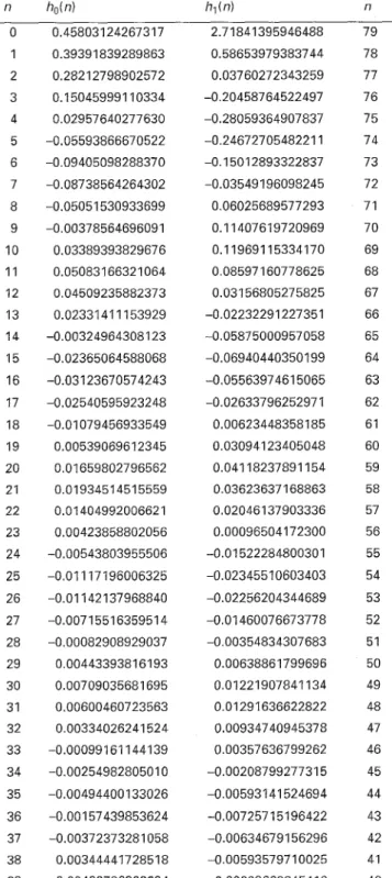
Table 3: Coefficients of the designed filters H,,(z) and h O ( n )
Hl(z) for example 1 0 0.45803124267317 2.7 1841 395946488 79 I I I I I 0 1 2 3 4 5 6 7 8 9 10 11 12 1 3 14 15 1 0.39391839289863 0.58653979383744 78 2 0.28212798902572 0.03760272343259 77 3 0.15045999110334 -0.20458764522497 76 4 0.02957640277630 -0.28059364907837 7 5 5 -0.05593866670522 -0.2467270548221 1 7 4 6 -0.09405098288370 -0.15012893322837 7 3 7 -0.08738564264302 -0.03549196098245 72 8 -0.05051 530933699 0.06025689577293 71 9 -0.00378564696091 0.11407619720969 70 n h&n) h l ( n ) n 1.23618061095655 2.038782587 181 31 31 0.6036636881 4555 -0.17085591 494049 30 -0.06593423400779 -0.46462363986519 29 -0.26250252196451 -0.1689559432 1699 28 -0.05978007203571 0.14027327860362 27 0.124582 10425695 0.1738581 10801 91 26 0.08099324386912 0.01 87 137651 3089 25 -0,04535651 182571 -0.09339193740865 24 -0.06563937 131 828 0.00403015855316 0.04055005846851 0.01 116042939344 -0.01873820489688 -0.01 445539655885 0.01 185217520092 0.00335802636641 -0.06633719998891 0.01 689334155360 0.04892162177594 0.01852213686230 -0.01720549184744 -0.0214631 534631 4 -0.00683499670667 0.00405233023957 23 22 21 20 19 18 17 16
!i
a
-10i I 1
ar L ar U 2 -60 mE
-80 - C r 2 0.02 E O LA @J U t I 2 - -0 02 E -0.06 -0.08 -0.1 0 0 .I 0.2 0.3 0.C 0.5 normaitsed frequency bFig .4 Results fov example 2
a Magnitude responses of the designed analysis filters; (I) Ho(w)/d(LLo); (ii)
b Magnitude response of the designed filter bank
N,(w)i'l(LL,)
5 Conclusion
This paper has presented a technique for the minimax design of two-channel nonuniform-division filter 94 10 11 12 1 3 14 15 16 17 0.03389393829676 0.05083166321064 0.04509235882373 0.02331411153929 -0.00324964308123 -0.02365064588068 -0.03123670574243 -0.02540595923248 0.11 9691 153341 70 0.085971 60778625 0.03156805275825 -0.02232291227351 -0.05875000957058 -0.06940440350 199 -0.0556397461 5065 -0.0263379625297 1 69 68 67 66 65 64 63 62 18 -0.01079456933549 0.00623448358 185 61 19 0.00539069612345 0,030941 23405048 60 20 0.01659802796562 0.04118237891 154 59 21 0.01 93451 451 5559 0.03623637168863 58 22 0.01404992006621 0.02046137903336 57 2 3 0.00423858802056 0.00096504172300 56 24 -0.00543803955506 -0.01522284800301 55 25 -0.01 117196006325 -0.02345510603403 54 26 -0.01 142137968840 -0.02256204344689 53 27 -0.00715516359514 -0.01 460076673778 52 28 -0.00082908929037 -0.00354834307683 51 29 0.00443393816193 0.0063886 1799696 50 30 0.00709035681695 0.01 221 907841 134 49 31 0.00600460723563 0.01 291 636622822 48 32 0.00334026241524 0.00934740945378 47 33 -0.00099161144139 0.00357636799262 46 34 -0.0025498280501 0 -0.00208799277315 45 35 -0.00494400133026 -0.00593141 524694 44 36 -0.00157439853624 -0.007257 151 96422 43 37 -0.00372373281 058 -0.00634679156296 42 38 0.00344441728518 -0.0059357971 0025 41 39 0.00422786323294 -0.00009662845410 40
(NDF) banks with linear-phase FIR filters. The design problem has been formulated as an optimisation prob- lem based on a linearisation scheme. A design method has been developed
based
on the
use of a
modified dual-affine scaling variant of Karmarkar's algorithm for updating the filter coefficient vector. Appropriate selection of the initial guess has been presented for ini- tiating the design process. Moreover, an analytical for- mula has been proposed for calculating the step size required at each iteration. As a result, the coefficients of the analysis filters can be obtained efficiently by solving only linear equations during the design process. Simulation results have shown the effectiveness of the proposed design technique.6 Acknowledgment -H,(d") into eqn. 37 yields
X ( e J W ) = T ( e J " ) X ( e J " )
+
A1( e J w ) X ( e J " W t " )
+
A 2 ( e 3 w ) X ( e 3 w W L 1 ) (38)where This work was supported by the National Science
Couiicil under Grant NSC86-222 1 -E002-025.
7 1 2 3 4 5 6 7 8 9 References
CROCHIERE, R.E.: 'Digital signal processor: sub-band coding',
Bell Syst. Tech. J., 1981, 60, pp. 1633-1653
BELLANGER, M.G., and DAGUET, J.L.: 'TDM-FDM trans- multiplexer: digital polyphase and FFT', IEEE Trans., 1974,
COM-22, pp. 1199-1204
VARY, P., and HEUTE, U,: 'A short-time spectrum analyzer with polyphase network and DFT', Signal Process., 1980, 2, pp. 55-65
WOODS, J.W., and O'NEIL, S.D.: 'Subband coding of images',
IEEE Trans. Acoust. Speech Signal Process., 1986, ASSP-34, pp. 1278-1288
KOVACEVIC, J.: 'Filter banks and wavelets: Extensions and applications'. PhD. dissertation, Columbia University, New York, NY, October 1991
NAYEBI, K., BARNWELL, T.P., and SMITH, M.J.T.: 'Nonu- niform filter banks: a reconstruction and design theory', IEEE
Trans. Signal Process., 1993, 41, pp. 11141127
WADA, S.: 'Design of nonuniform division multirate FIR filter banks'. IEEE Trans. Circuits Svst. II. Analog I , Digit. Signal Proc- Y
e.s.s., 1995, 42, pp. 115-121
LEE, J.-H., and HUANG, S.-C.: 'Design of two-channel nonuni- form-division maximally decimated filter banks using L, criteria',
IEE Proc., Vis., Image Signal Process., 1996, 143, (2), pp. 19-83 ADLER. I.. KARMARKAR. N.. RESENDE. M.G.C.. and VEIGA,'G.': 'An implementation of Karmarkar's algorithm for linear programming', Math. Program., 1989, 44, pp. 297-335 10 KARMARKAR, N.: 'A new polynomial-time algorithm for lin-
ear programming', Comhinutorica, 1984, 4, pp. 373-395
11 VANDERBEI, R.J., MEKETON, M.S., and FREEDMAN, B.A.: 'A modification of Karmarkar's linear programming algo- rithm', Algorithmica, 1986, 1, pp. 395407
12 RUZINSKY, S.A., and OLSEN, E.T.: 'L, and L, minimization via a variant of Karmarkar's algorithm', IEEE Trans. Acoust.
Speech Signal Process., 1989, ASSP-31, pp. 245-253
13 HILLER, F.S., and LIEBERMAN, G.J.: 'Introduction to mathe- matical programming' (McGraw-Hill, New York, 1991)
14 LIM, Y.-C., LEE, J.-H., CHEN, C.-K., and YANG, R.H.: 'A weighted least-squares algorithm for quasi-equiripple FIR and IIR digital filter design', IEEE Trans. Signal Process., 1992, 40,
15 RABINER, L.R., and GOLD, B.: 'Theory and application of digital signal processing' (Prentice-Hall, Englewood Cliffs, NJ, 1975)
pp. 551-558
8 Appendix
Let Bo(") and B l ( z ) be LP FIR filters with lengths equal to Nbo and N b l , respectively. The associated maguitude responses are set to Bo(u) = 1, for U E [0, uJLO] and = 0, for w E [(2n - w,)iLo, n] and Bl(w) = 1, for o E [0,
(n
- wp)iL1] and = 0, for w E[(n
+
wp)iL1,n],
respec-tively. Moreover, assume that Ho(z) and H,(z) have
zero stopband response. Then, it follows that the inputi output relationship of the NDF bank in the frequency domain is given by [8] e - 3 W G 0 LLO X ( e J w ) = ~ [ X ( e J w ) Ho ( e3" )
+
x
(eJWw,L
1 ) H~ ( e ~w,L
1 )+
x
( eJWw,
L1 ) H1( ej"w,
1 )] Fl ( e3 ) ( 3 7 )where Go = (Nbo - I)/Lo and GI = (N[,l - l)/L1 are set
to integers to avoid noninteger group delays. The twiddle factors W, = exp(-j2niL). Substituting the conditions L = Lo + L,, Fo(eJ'") = Ho(eI") and F l ( d w ) =
The first term of eqn. 38 represents the response of a linear shift-invariant system T(dW) with input
X(d"),
while the other two terms represent the resulting aliasing distortion. Therefore, perfect reconstruction requires the following conditions:PR 1: The magnitude
T(o)
of T(e-lw) must be equal to 1, i.e. T(u) = 1, for all U .PR 2: The magnitude A I ( @ ) of A,(@) must be zero, i.e.
A , ( u ) = 0, for all w.
PR 3: The magnitude A2(w) of A2(dW) must be zero, i.e. A2(w) = 0, for all w.
We note from eqn. 39 that Ho(z) must be either a case 1 or case 2 LP FIR filter, while H l ( z ) must be a case 4 LP FIR filter to ensure the PR 1 condition. The definitions for each of the case 1 to 4 of LP FIR filters can be found in [15]. Let Ho(z) and H l ( z ) be LP FIR filters with lengths equal to No and N1, respectively. Then, Ho(eJ") can be expressed as [15]
(42) ( N o - 1 ) ~ Ho(e3") = e - J T H o ( w ) where N o - 3 f - h o ( Y ) +
5
2ho(n)cos(w(n-F))
n=O Ho ( U ) = for case 1 and ho(n) ilarly, we wheredenotes the impulse response of Ho(dW). Sim- can express Hl(dIW) as [15]
(43)
( N 1 - l ) w
HI(.+) = j e - j T H l ( w )
and hl(n) denotes the impulse response of Hl(elW). Sub- stituting eqns. 42 and 43 into eqn. 39 yields
+
-e -3(G1+N1--l)"H?(w) (44)LL1
Let Do = Go
+
No - 1 and D , = GI + N I - 1 . If DOD,,
then exp(-j(Do - D l ) w ) must be included in thehighpass subband channel, and, if Do < D 1 , then exp(-j(D, - D o ) o ) must be included in the lowpass sub-
95 IEE P r o c V i s . Image Signal Process., Vol 145, No. 2, April 1998
band channel to equalise the group delay difference, 1
+
-ffi (0)ffi (U - u p - U , )(46)
LL1
and, hence, ensure the PR1 condition. Hence, we can
neglect the LP term of eqn.
44
and expressT(w)
as andWS :
1 1
T ( w ) = ---;(U)
+
--H,2(U) (45)LLn LL1
Next, substituting eqns. 42 and 43 into eqns. 40 and 41,
1
we can obtain
respectively, where the related gro
between the lowpass and highpass subband channels is also assumed to be equalised.
1
LLO
A , ( w ) =