The 2004 IEEE Asia-Pacific Conference on Circuits and Systems, December 6-9,2004
DESIGN AND SIMULATION OF A MIMO OFDM BASEBAND
TRANSCEIVER FOR HIGH THROUGHPUT WIRELESS LAN
Chi-Yeh
Yu,
Zih-En Ding, and Tzi-Dar Chiueh
Graduate Institute
of
Electronics Engineering
and Department of Electrical Engineering
National Taiwan University, Taipei, Taiwan 10617
chiueh@cc.ee.ntu.edu.tw
ABSTRACT
This paper proposes a MlMO
OFDM
baseband transceiver design for the next-generation high-throughput wireless LAN using two transmit antennas and two receive antennas. A MIMOOFDM
receiver with algorithm for timing and fre- quency synchronization, tracking. channel estimation, and MIMO detection is designed and implemented in software. Simu- lation results show that the proposed receiver is capable of transmission with a data rate that is twice that of the current IEEE 802.1 l a wireless LAN standard.1. INTRODUCTION
One of the main objectives of current wireless communica- tion research is to increase the link throughput in a spectrally- efficient and reliable manner. Multiple-input multiple-output (MIMO) techniques have the potential of increasing the trans- mission rate by several folds [I]. In general, there are two types of MIMO techniques: (a) rate maximization schemes such as vertical Bell Laboratories Layered Spare-Time code (V-BLAST) [21 and (b) diversity maximization schemes such as space-time block %de (STBC) [31. The former can achieves a higher data rate, while the latter gains more diversity. Both types of MlMO techniques were developed originally for flat fading channels, and lately have been applied to orthogonal frequency division multiplexing
(OFDM)
technology used in frequency-selective fading channels.In this paper, we propose a baseband transceiver capable of doubling the data rate of IEEE 802.1 la standard with two transmit and two receive antennas. The data rate ranges from
6 x 2 Mbps to 54 x 2 Mbps. A new packet format based on the original format is designed for accommodating MIMO channel estimation. Moreover, several synchronization algo- rithms for MIMO OFDM receiving are implemented. Func- tional simulation results of the proposed receiver establish the validity of it effectiveness in high-throughput wireless LAN applications.
The organization of the paper is as follows. Section 2 describes the system as well as the packet format. Section
3 gives the receiver architecture and explains respective al- gorithms. In Section 4 the simulation results are provided. Finally, conclusions are drawn in Section 5 .
2. SYSTEM DESCRIPTION AND PACKET FORMAT
The proposed MIMO OFDM system is illustrated in Fig. 1.
At the transmitter, data symbols are first processed by MIMO transmission techniques. The MIMO transmission will ar- range symbols in 2 x 2 VBLAST or in 2 x 2 STBC according to the adopted data rate. The processed data symbols are then sent to an IFFT operation and a cyclic prefix (CP) is inserted. At the receiver, CP is removed, and the data symbols are re- covered after an FIT operation. Finally, data symbols are equalized, and then detected.
Fig. 1. MIMO OFDM system model.
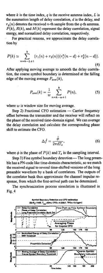
Physical layer key parameters used in the proposed MlMO OFDM transceiver are listed in Table 1. Note that all are com- patible with the IEEE 802.11a standard. Additional double data rates newly provided by the MIMO techniques are listed in Tabie 2. Note that VBLAST-OFDM can achieve a higher throughput due to parallel transmission, while STBC-OFDM gains more diversity by coding over different branches.
The new MIMO OFDM packet format is shown in Fig. 2.
The preamble consists of 10 short symbols, denoted as t l to
t l o , and four long symbols, denoted as TI to T4. The pream-
ble is followed by the SIGNAL field and DATA symbols. Identical to the IEEE 802.11a standard, the short preamble utilizes only 12 out of 52 suhcaniers, whose indices are a mul- tiple of 4, and hence results in a periodicity of T~p1-14 = 0.8 us. The long preamble also reuses the IEEE 802.1 l a design, with 52 subcaniers (excluding a zero value at DC) modu- lated by a fixed f l sequence. The period of long preamble is TFFT = 3.2 us. ?*.o periods are preceded by a guard interval
(GI) of 1.6 us. For MIMO channel estimation, there are four periods and the last two periods and the associated GI in one of the transmitter are inverted.
Baseband
Receiver
Modulation type
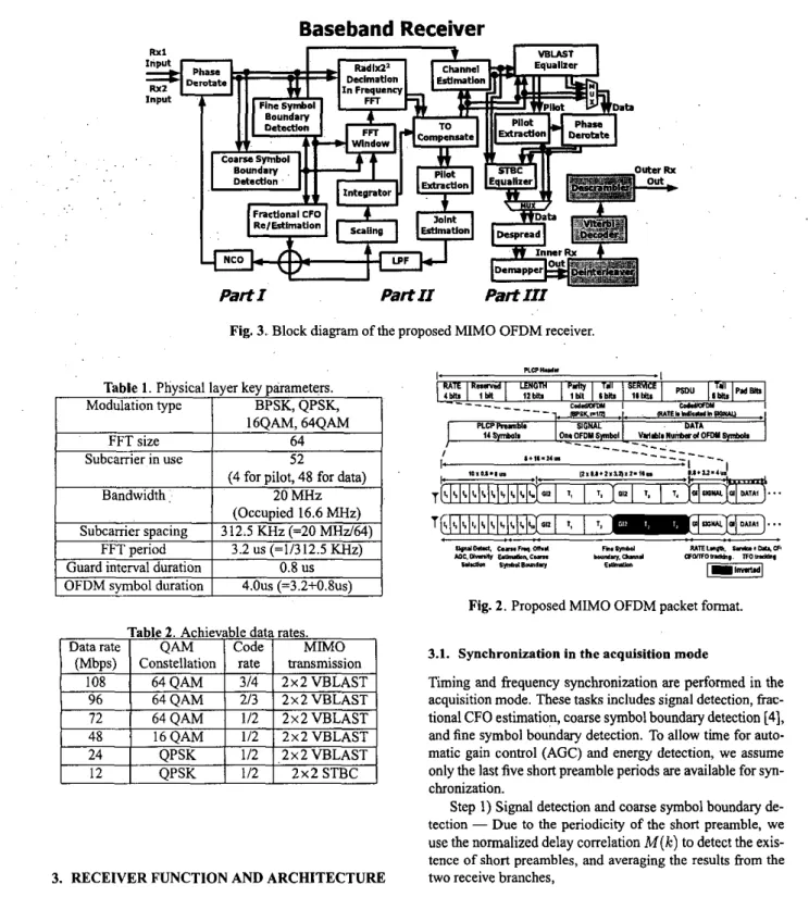
Fig. 3. Block diagram of the proposed MIMO OFDM receiver
BPSK, QPSK, 16QAM, 64QAM \
. ,
108 96 12 48 24I
SubcamerinuseI
521
64QAM 314 2x2VBLAST 64QAM 213 2x2VBLAST 64QAM 112 2x2VBLAST 16QAM 112 2x2VBLAST OPSK 112 2x2VBLASTI
(4 for pilot, 48 for data)Bandwidth
I
20 M H ZTable 2. Achievable data rates.
I
DatarateI
OAMI
CodeI
MIMOI
(Mhos)
I
ConstellationI
rateI
transmission1
12
I
QPSKI
112I
2x2STBC3. RECEIVER FUNCTION AND ARCHITECTURE
The overall receiver functional block diagram is shown in Fig. 3. We divide the receiver into three parts:
Part
I is respon- sible for timing and frequency synchronization in the acqui- sition mode; Part 11 is intended for residual carrier frequency offset (CFO) tracking and residual timing offset (TO) track- ing; and Part 111 deals with channel estimation and data recov- ery.3.1. Synchronization in the acquisition mode
Timing and frequency synchrooization are performed in the acquisition mode. These tasks includes signal detection, frac- tional CFO estimation, coarse symbol boundary detection [4], and fine symbol boundary detection. To allow time for auto- matic gain control (AGC) and energy detection, we assume only the last five short preamble periods are available for syn-
chronization.
Step 1) Signal detection and coarse symbol boundary de- tection - Due to the periodicity of the short preamble, we use the normalized delay correlation
M ( k )
to detect the exis- tence of short preambles, and averaging the results from thetwo receive branches,
q = l n=k-L+1
where
k
is the time index, 9 is the receive antenna index,L
is the summation length of delay correlation, d is the delay, andrg(n) denotes the received n-th sample fiom the q-th antenna.
P ( k ) , R(k), and M ( k ) represent the delay correlation, signal energy, and normalized delay correlation, respectively.
For practical reasons, we approximate the delay correla- tion by
k
P ( k )
N ( ~ i ( n )+
TZ(TL))(T;(TL-
d ) + T ; ( T L - d ) ) .(4) After applying moving average to smooth the delay correla- tion, the coarse symbol boundary is determined at the falling edge ofthe moving average
PaUe(k),
n=k-L+l (5) l k Pa”&) =
-
c
P(.),
n = k - u + l Wwhere w is window size for moving average.
Step 2) Fractional CFO estimation
-
Carrier frequency offset between the transmitter and the receiver will reflecton
the phase ofthe received time-domain signal. We can average the delay correlation and calculate the corresponding phase shift to estimate the CFO.
A f = -
“
4
2?rdT,’
where q5 is the phase of
P ( k )
andT,
i s the sampling interval. Step 3) Fine symbol boundary detection-
The long pream- ble has a PN-code like time-domain cbaracteristic, so we match the received s i p a l to several time-shilled versions of the long preamble waveform by a bank of correlators. The outputs of the correlator bank thus approximate the channel impulse re- sponse, from which the first-arrival path can be determined.The synchronization process simulation is illustrated in Fig.~4
,6bi*)=1cda,Tm:l(n., cFO-apL11. r r ( b l l . , # p ” I
Fig. 4. Synchronization process when receiving the pream-
bles of a packet.
3.2. CFORO tracking
Though residual CFOITO are small after fractional CFO com- pensation, the accumulated phase rotation can still deteriorate system performance as time goes by. Consequently, we need a CFO/TO tracking loop to dynamically compensate such sig- nal phase drift.
least squares (WLS) algorithm [ 5 ] . Because we have double the number of pilots from two branches, the accuracy can be enhanced when compared to the case with single receiving antenna. Assume there is only one oscillator in the receiver,
WLS algorithm can he simplified, and we can estimate the CFO first and scaling $e CFO by a constant to get the TO. For IC1 level and simplicity, we choose compensate the CFO in the time domain and compensate the TO in the frequency do- main. To limit the noise, we introduce a first-order low-pass proportional-integral (PI) filter in the tracking loop. Finally,
as the sampling timing overtlows or underflows, we sbit? the FFT window forward or backward by one sample so as to avoid inter-symbol interference.
To estimate the residual CFOITO, we adopt the joint weighted
33. Channel estimation and data recovery
The long preamble is especially designed for MIMO chan- nel estimation. By inverting the last two periods of the long preamble in one of the transmitter, we can adopt the STBC combining method to estimate the channel as in [4]. The two
extra periods of long preamble can also improve the channel estimation accuracy.
For a certain subcarrier
i,
the received symbol matrixR
can be expressed in terms of the transmit symbol matrix S ,
the channel matrix H, and the noise matrix N as
(7)
% , z ~ z
= S i , z x ~ H i , ~ x ~+
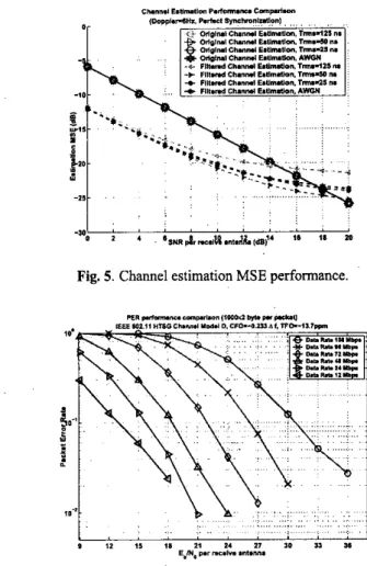
Ni,zxz. Channels can then be estimated byH1,zxz = s;;z1,z%.zxz. (8) In low SNR case, to further enhance the Channel estimation performance, we add a frequency-domain filter to smooth the estimation result. This filter is designed in such a way that its time-domain waveform is a window of proper shape and length to extract the channel impulse response and reject as much noise as possible [6]. Mean square errors of the esti- mated channel responses using the filtered and the unfiltered schemes are shown in Fig. 5 . The improvements of the filtered channel estimation method is quite apparent. Using the esti- mated channel responses, we can detect the VBLAST OFDM signal and STBC OFDM signal as described in [2] and [3], respectively.
4. SIMULATION RESULTS
The whole MIMO OFDM receiver is implemented in soft- ware and the simulated packet error rates (PER) of the de- modulated signals are depicted in Fig. 6. In this simulation, we use the IEEE 802.1 1 task group n channel model D, which models a typical ofice environment. The center frequency is set to be 5320 MHz, and the CFO and the TO are both set
6. REFERENCES
[I] G . J. Foschini and M. J. Gans, “On limits of wireless communications in a fading environment using multiple antenna,” Wireless Personal Commun., vol. 6 , pp. 31 1- 335, Mar. 1998.
[2] P.W. Wolniansky, G.J. Foschini, G.D. Golden, andR.A. Valenzuela, “V-BLAST an architecture for realizing very high data rates over the rich-scattering wireless channel,” in URSI Infernational Symposium on Signals, Sysfems, and Electronics, Oct. 1998, pp. 295-300.
[3] Siavash M. Alamouti, “A simple transmit diversity tech- nique for wireless communications,” IEEE J. Select. Ar- eas Commun., vol. 16,pp. 1451-1458, Aug. 1998.
[4] A. N. Mody and G. L. Stuber, “Receiver implementation for a MIMO OFDM system,” in Globecom, 2002, pp. 716-720.
[SI Pei-Yun Tsai, Hsin-Yu Kang, and Tzi-Dar Chiueh, “Joint weighted least squares estimation of frequency and timing offset for OFDM systems over fading chan- nels,” in Vehicular Technology Conference, April 2003,
vol. 4, pp. 2543-2547.
[6] Pei-Yun Tsai and Tzi-Dar Chiueh, “Frequency-domain interpolation-based channel estimation in pilot-aided OFDM systems,” IEEE VTC Spring, May 2004. [7] IEEE 802.11 TGn, “Comparison cnteria,”DCN: 11-03-
0814-1 16. Fig. 5. Channel estimation MSE performance.
I
” \ \
\
x1
\.’0.
~ . . . . : . : . , ~., , ~ . . . . . . . . . . . . . . . , . . . . . . . , . . . . . . . . ,. to-- . , . . . . . . i. . , . ...,. . I U 1, 1. 21 24 27 34 U aa E p , P.‘mc.h..”,.””.
Fig. 6. PER performance of the proposed MIMO OFDM re- ceiver.
at -13.7 ppm according to TGn comparison criteria [7]. The very small Doppler effect (6Hz) is neglected for simplicity.
From the simulation results, the PER performance of the system running at the highest data rate reaches
lo-’
at anEb/No of about 30
dB.
With the help of better outer coding, suchas
low-density product coding (LDPC), we can further improve the system performance to satisfy the functional re- quirement of the IEEE 802.1 1 task group n.5. CONCLUSION
In this paper, we propose a MIMO OFDM baseband inner transceiver design for the next-generation high-throughput wire- less LAN using two transmitting antennas and two receiving antennas. Algorithms for timing and frequency synchroniza- tion, tracking, channel estimation, and MIMO detection are designed and implemented. Finally, the PER performance of the receiver is presented and the results indicate that the proposed receiver is capable of delivering reliable transmis- sion with double the data rate achieved by the current IEEE 802.1 la standard