A multiprocessor system for
visual communications using
distributed transputer arrays
Wei-lou Duh, Ja-Ling Wu and lau-Hsiung Huang
A'transputer-based multiprocessor system for visual communica- tion applications is presented. H.261, the encoding/decoding stan- dard for video telephones recommended by CCITT, is implemented in this system for demonstration. Fundamental video processing operators, such as 3 x 3 discrete Laplacian, a r e also implemented. Up to 20.4 frames per second (fps) video replaying rate and about 7.2 fps processing rate for executing 3 x 3 linear filtering are obtained. Analyses and guidelines for designers wishing to build multiprocessor systems for visual communications are also given. Such a system is fast and flexible for experimenting with new algorithms and is an excellent CAI (computer aided instruction) tool in teaching video processing. Keywords: video telephone, transputer array
Advances over the past decade in many aspects of digital technology have brought about many video applications, such as multimedia presentations, HDTV (high-definition TV), video telephones and video conferencing. All these video applications rely upon well-developed compression techniques. In multimedia systems, various media are inte- grated together, with the aid of a user-friendly interface, to process and to carry information. There are many kinds of media, including text, data, speech, sound, graphs, images, animation, video and so on. Video signals, due to their tremendous data volume, introduce many problems in storage, processing and transmission. HDTV is the next generation digital TV and the compression of digital TV signals is one of the dominant factors of the success of the HDTV. Video phones and video conferencing 1'2 are regarded as the most popular video applications in the near Communication and Multimedia Research Laboratory, Department of Computer Science and Information Engineering, National Taiwan Univer- sity, Taipei, Taiwan, R.O.C.
Paper received: 2 December 1991. Revised: 5 March 1993
future. Because of the urgent needs of visual communica- tions, a worldwide standard for video phones, H.261, was proposed by CCITT.
The data rates of video phones and video conferencing are much less than those required in multimedia systems and HDTV. Slower motion and lower resolution make the implementation of video phones easier. Since all video applications suffer from tremendous data volume, video compression is the key technology to bring them to the real world.
When processing video signals, objective and subjective assessments are both of importance. Therefore, in the development phase of a video compression algorithm, many passes of experiments must be carried out. For example, tens or hundreds of test video sequences should be tested when a new compression method is devised to investigate the resulting objective and subjective qualities and to adjust parameters to obtain the best video quality. Also, various reference algorithms are applied to the same set of test sequences for comparison. Therefore, short turn- around time of the compression/decompression experi- ments is required in the development phase. Since it is more costly and less flexible to build special hardware for simulation before the compression algorithm is finalized, a software based simulation tool is more appropriate in designing various algorithms. A multiprocessor-based image coding system using DSP was presented in Refer- ence 3. It is a different approach compared to our system; nevertheless both systems adopt geometric decompositions and each processor handles one strip of image.
In order to achieve the short turn-around time require- ment in software simulations, parallel processing seems to be a necessary approach. For a parallel processing system with n processors, we define efficiency as:
efficiency = processing time using one processor (1) processing time using n processors x n 0141-9331/94/020079--09 © 1994 Butterworth-Heinemann Ltd
A multiprocessor system for visual communications: W-J Duh et a/. Clearly, a high efficiency value is desired for parallel processing systems. Since most of the video processing operations possess the property of regular data flow, the efficiencies of simulating these algorithms in parallel computing environments are usually high. In Reference 3, an MIMD (multiple instruction multiple data) architecture which consists of about 40 processors was adopted to accelerate the computation of encoding/decoding, and the efficiency is about 0.89. However, the time to encode/ decode a frame is too long and it is therefore impossible to process on-line a video sequence in real-time.
In this paper, a muhiprocessor system designed to meet the requirements for visual communications is presented. The time to encode/decode a video frame is very small in our implementation using multiple transputers. In order to achieve a small encoding/decoding time, a lower level programming style is adopted to avoid the overheads of the operating system. Previous work can be found in Refer- ence 4. In our simulation system, the efficiency of H.261 simulation is higher than that in Reference 3. During the period of implementing the system, many issues are encountered such as the physical link number constraints, the overlapping of communications/computations and the selection of topology.
OVERVIEW OF H.261
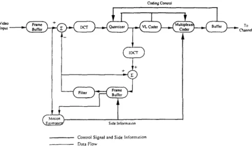
The H.261 recommendation is an international standard for video coding proposed by CCITT. It describes the coding and decoding method for the moving picture components of audio-visual services at the rate o f p x 64 kbits -1, where p is in the range of 1 to 30. In the recommendation, CIF (common intermediate format) or QCIF (quarter CIF) image formats, hybrid intraframe DCT (discrete cosine trans- form) s-7 and intefframe DPCM (differential pulse code modulation) coding methods with motion compensation are adopted, as shown in Figure 1.
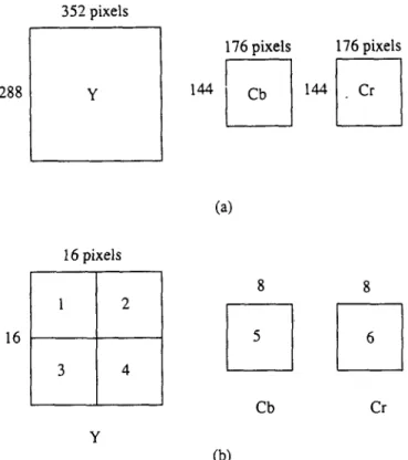
In the CIF format, the luminance sampling structure is 288 lines per picture, 352 pixels per line in an orthogonal arrangement. Sampling of each of these two colour differ- ence components is at 144 lines, 176 pixels per line, also orthogonally arranged. The QCIF format has half the number of pixels per line and half the number of lines per
picture as in the CIF format. Each picture frame is first divided into macro-blocks, each of which consists of one 16 x 16 luminance block and two corresponding 8 × 8 chrominance blocks. The 16 x 16 luminance block is further divided into four 8 x 8 sub-blocks. Figure 2 shows the CIF format in Y, Cr, Cb components. The key aspect of the H.261 algorithm is that the transform is performed on each 8 x 8 block independently and motion estimation is performed on the 16 x 16 luminance macro-blocks.
The transform chosen by H.261 is the DCT. It is performed either on the 8 x 8 blocks of the current frame (in intra-frame mode) or on the residual signals which could not be predicted from the previous frame (in inter- frame mode). The output of the DCT is a coefficient matrix which shows the distribution of energies in the two-dimen- sional transform domain. In general, most of the energies are concentrated on the upper left corner of the matrix, that is, low frequency components dominate the energy distri- bution. If the coefficients are scanned in a zig-zag order, the resulting sequence will contain long strings of zeros especially toward the end of the sequence and the two- dimensional coefficients are converted to a one-dimen- sional sequence, ordered from low to high frequency components.
A uniform quantizer is cascaded to the DCT transformer. After quantizing the transform coefficients, the coefficients are zig-zag scanned, run-length coded, and finally vari- able-length coded. The coded coefficients are then multi- plexed with other side information (such as macro-block coding types, quantization level and motion vectors) to be sent to the communication channel. An optional low-pass filter is applied to the DPCM feedback loop for the purpose of smoothing out the reconstructed noise. The decoder performs the inverse operations of the encoder. The focus of our system is on accelerating the video coding computing using a parallel processing system. Therefore, many aspects of video coding/decoding ~ are beyond the scope of this paper.
THE DISTRIBUTED TRANSPUTER ARRAY
The transputer is a microcomputer with its own local memory and four pairs of links for connecting to other
Video Inpul n e i :i Codin@ Conuol
D
To C~ann¢lFigure 1 Block diagram of the H.261 encoder
Control Signal and Side Informalion Data Flow
A multiprocessor system for visual communications: W-J Duh et al. 288 352 pixels ¥ 176 pixels 176 pixels 144 Cb 144 Cr
• Two IMS C004 crossbar switches provide flexible configurability. The IMS C004 is a 32-way crossbar switch that supports the Inmos link protocol and is soft- ware-configurable.
• One IMS B007 board is used as the graphic display controller. The B007 board contains one T414 trans- puter and supports 512 x 512 spatial resolution with 256 out of 262 144 colors. (a) 16 16pixels
1
2
3 48
8
5 6 Cb Cr Y (b)Figure 2 CIF format: a, structure of a CIF frame; b, structure of a macro block
The transputer array is treated as a back-end MIMD system with the interconnections between processors as shown in Figure 3. The processors are primarily connected as a linear array. Each processor can communicate with non- neighbourhood processors via the C004 programmable crossbar switches. The concurrent programming language used to develop the system is Occam 212.
Because there are 42 processors in the array, one C004 crossbar switch cannot support full connectivity between processors. Therefore, transputers numbered from 1 to 20 are connected to the first C004 and the others are connected to the second C004. There are 10 links connecting these two C004s to provide the capability of inter-crossbar communications. For example, processor 1 can be connected to processor 21 through one of these inter-crossbar links. The transputer on the B007 graphic board is connected at the end of the array and also to both C004 crossbar switches via links 2 and 3.
transputers. A typical member of the transputer family is a single chip which contains the processor, the memory and communication links providing point to point connections between transputers. The T800 transputer was chosen to construct the simulation system. It is a 32-bit micro- processor with floating point unit (FPU) and 4 kbytes cache memory on chip. The computing power of an IMS T800 transputer is 10 MIPS (or 2.25 Mflops) at 25 MHz clock speed 9.
Because there are only four pairs of links in one trans- puter, the connectivity of the transputer network is heavily restricted. Some popular topologies of transputer networks are linear arrays, meshes and trees. In the fields of
10
computer architectures and networks, many well-known topologies are difficult to implement using transputer arrays. It is obvious that only those topologies with maximal input/output degree less than 4 can be directly constructed by using transputer arrays. Therefore, higher order hypercubes, stars, trees and so forth, are rarely considered in transputer arrays. This explains why only linear array and mesh structures are discussed in this paper.
The hardware platform of the system is as follows: • One IBM compatible 386-PC is used as the host
machine which is in charge of keyboard inputs, screen outputs and file accesses.
• One IMS B008 evaluation board attached to the host PC containing 2 Mbytes of dynamic RAM and a T800 trans- puter for running the transputer development system (TDS2)I 1.
• Ten IMS B003 boards, each consisting of four T800 transputers, are treated as node processors which are hardwired in a ring structure. There are 256 kbytes of local memory on each T800 transputer in the system.
THE REAL-TIME SIMULATION SYSTEM
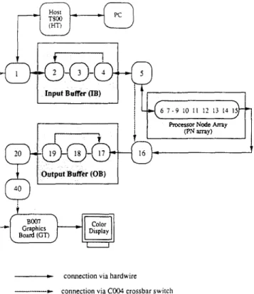
The system uses 21 out of 40 transputers as shown in Figure 3. Some of them are used as I/O buffering and controlling. In fact, only nine transputers are allocated for coding processing. The system consists of five parts, the host transputer (HT), the input buffers (IB), the output buffers (OB), the processing nodes (PN) and some control
I( 13oo3
J L,3003
; LProgramrrmblc Crossbar Switch (COIN.) #2
Figure 3 Hardware configuration of the transputer array
A multiprocessor system for visual communications: W-J Duh et al.
©.'
Board (GT)
I I
i,, connection via hardwire
~ . ) . - connection via C004 crossbar switch
Figure 4 Mapping of functional blocks to physical transputers
transputers (including host controller, distributing con- troller, collector controller, bypass controller and graphic transputer). The mapping of these parts to physical trans- puters is shown in Figure 4. All transactions between console (PC) and the transputer network are monitored by the host transputer, such as file accesses, keyboard/screen I/O and so on.
The 113 and OB are used, respectively, to store the original video sequence and the processed one. The IB and OB are not merely used for video storage but also provide compatible communication bandwidth to the processing array. Therefore, the I/O bottlenecks in video systems are avoided by using I/O buffering. The frames circulate in the buffer ring when the 'start next frame' command arrives at the head node of the ring. The OB ring is operated in the same way as the IB one. Processed frames are loaded from the PN array to OB and sent to the B007 display board.
Restricted by the 13007 board, the testing format is a grey- levelled QCIF video. Both IB and OB consist of three transputers with seven frames in each node. Therefore, 21 frames are circulated in IB and OB. If the testing video sequence is long, the local memory must be expanded to 16 MB and more transputers should be allocated to IB and OB. IB can support a 20.4 fps input rate and OB can support a 19.3 fps playing rate when the link is working at a 20 Mbits -1 communication rate.
The PN array is a bidirectional linear array. The forward links are used to distribute the current frame and the back- ward ones are used to send the previous frame to the corresponding neighbour processors. There are nine trans- puters in the PN array because the QCIF image is divided into nine horizontal macro-block strips whose dimensions are 176 x 16 each. Geometrical decomposition of each frame is the method adopted in the system. Although the amount of inter-node communications are reduced in mesh
structures, the efficiency for transferring 2D data blocks i< worse than 1D ones. The time for transferring a 1D data block between neighbouring nodes is usually modelled as:
T~ = T~tup + n- T~ (2)
where Tsetu p is the setup time of the communication channel, n is the number of bytes to be transferred, and Tt, is the time to transfer one single byte. A2D data block of size n = p x q is modelled as:
T2 = p(Tsetu p + q" Th) (3)
where p is the number of discontinuous segments in n bytes. The effect becomes more visible as p or T,~tup/T~, increases. The dimension of the QCIF format is small and thus the linear array of the transputer is adopted.
Table 1 shows the measured communication overheads for transmitting image blocks using transputers. Tsetup and Tb can be estimated by fitting the numbers in Table 1 into Equations (2) and (3). It shows that Tset~p(10Mbitss -~) 101is, Tse~p(20Mbitss -1) ~ 7.51ls, Tb(10Mbitss -T) ~ 1.1211s and Tb(20Mbitss -1) ~ 0.561ls.
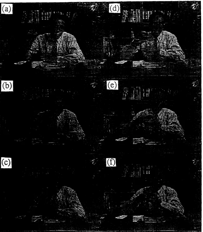
Each node processor encodes/decodes one strip of image and two neighbouring strips are also stored as references during computation. Since the maximum search range of the H.261 recommendation is from - 1 6 to +15, only the data in strip i - 1 and i + 1 would be referenced when strip i is being processed. This is a trade-off between extra memory and the time of the search-range data commu- nications. No communications occur during the computing phase because most video processing algorithms require only local image data. Figure5 shows the original 'salesman' sequence and Figure 6 demonstrates the effects of the 'inter-frame mode' coded sequence. Several func- tions are provided in the system:
• Down-load video: loads video from host to lB. • Up-load video: receives video from OB to host. • Play IB: plays the original video stored in 18. • Play OB: plays the processed video stored in OB.
Table 1 Effects of 2D memory transfer versus message size, in terms of communication time
Channel speed: 10 Mbitss -1
1D 2D
Size Comm. time (ms) Size Comm. time (ms)
256 0.32 16 x 16 0.45
1024 1.15 32 x 32 1.47
4096 4.61 64 x 64 5.25
16384 18.43 1 2 8 x 128 19.78 Channel speed: 20 Mbits -~
1D 2D
Comm. time (ms) Size
Size Comm. time (ms)
256 1024 4096 16384 0.13 16 x 16 0.26 0.58 32 x 32 0.83 2.37 64 x 64 2.82 9.22 1 2 8 x 128 10.18
A multiprocessor system for visual communications: W-J Duh et ah
Figure S Original salesman sequence. (a)-(f) correspond to frames 1, 5, 9, 13, 17, 21
• H.261 simulation: H.261 coding/decoding simulation. • Video processing: fundamental video processing. As the processing goes on, the processing procedure is divided into two phases. In the first phase, each node sends its own macro-block strip in the backward direction in order to propagate the previous frame to its neighbouring node. While in the second phase the PN array transmits the processed frame to the collector and receives the next frame from the DC concurrently. Therefore, each frame requires a two-phase processing. This procedure repeats for each frame and terminates as the user issues an interrupt. Each node transputer in the PN array holds three macro- block strips of the current frame and three reference strips of the previous frame. The neighbouring strips are stored to
avoid irregular inter-node data communications. All computing operations in the video phone coding are performed at every node transputer, including motion esti- mation 13, frame difference, DCT transform, decision control and variable length coding.
SYSTEM ANALYSIS
Various approaches to simulate H.261 are discussed in Reference 14. Since the problem is computationally inten- sive and locally dependent, geometrical decompositions for parallel processing are adopted.
When using a linear array structure with P processors, one image frame, with dimension N = N1 x N 2, is divided
A multiprocessor system for visual communications: W-J Duh
et at.
Figure 6 The H.261 8:1 compressed sequence. (a)-(f) correspond to frames 5, 9, 13, 17, 21
into P strips of sub-images and each sub-image is distrib- uted to the corresponding processors. Each node receives and processes its own sub-image. Finally the processed sub-images are collected and merged to form a complete frame. Therefore, each pixel must travel through the entire array and the communication time, including distribution and collection, is:
Tcomrn(Linear) =
2P( N1
-~
x N 2 )Tb = 2NTb
(4) The distribution and collection time of a P~ x P2 mesh connected array is:Tcomm(Mesh) = 2P(~--~1 x N 2 )
x ,°2 Tb
2NTb
(5)It is clear that Equation (4) equals Equation (5), hence the following statement is obtained. If applications merely require one pass of processing, the topologies do not affect the communication overheads.
If the setup time of communication channels is counter, then; × N2
Tcomm(Linear) = 2P(Tsetup + ( NI ~
) Tb)
= 2PTsetup +2NTa
(6) and Wcomm(Mesh) = 2 P ( - ~ - (Tsetup q--~-Tb))
= 2P1N2Tsetup -F2NTb
(7)A The difference of the distribution/collection time between linear array and mesh structure is P1 (N2 - P2)Tsetup. In video processing, distribution of the next frame and collection of the processed frame can be overlapped and thus Tcomm(Linear) and Tcomm(Mesh) can be reduced by a factor of 2.
To simulate a video application, the geometrical decomposition is efficient. The data flow and the prece- dence of communication and computation processes are first determined. Then the communication (including distribution/collection and synchronization message) time can be estimated according to Equation (6). The computa- tion time can also be estimated in advance. For example, the 3 x 3 convolving window requires nine multiplications and eight additions per pixel. Each PE computes the results of (N1 x
N2)/P
pixels and thus requires about (9N1 xN2)/P
multiplications and (8N1 x N2)/P additions. The total processing time could be formulated as:
Ttotal : Tcomm + Tcomp -- ~ min(Tcomm, Tcomp) (8) where ~ denotes the overlapping factor between commu- nication and computation processes and 0<..%~< 1. Normally, c~ is a function of P, Tcomm and Tcomp.
For a special case, if NTb >> PTsetup, the effect of setup time could be ignored. Thus, the throughput of the system depends upon P and ~. As P increases, Tcomp decreases. Since Tcornm'iS constant for a fixed-sized image format, it is more efficient as Tcomm ~ Tcomp by choosing proper P. The worst case of Ttotal occurs as :~ approaches 0 (no over- lapping). In order to promote the performance of the system, many programming techniques could be applied to increase c~, such as double buffering.
It is never correct to predict the performance of a soft- ware system by using the 'hardware specifications', such as communication bandwidth and computing power, since the performance of a software system depends upon the compiler, the features of the CPU, the programming tech- niques and so on. It is much more realistic to predict the performance by measuring some basic 'software modules', such as the time for transmitting one data segment using specific programming techniques.
RESULTS AND PERFORMANCE
In order to achieve high efficiency and speed-up in the parallel simulation system, the following requirements must be satisfied.
Load balancing. The subtask that is distributed to each node must be balanced in order to avoid bottlenecks. The video frame is evenly partitioned into nine strips and dis- tributed to their corresponding processors. Therefore, the computational loads are almost balanced except that the first and the last processors perform fewer operations ow- ing to the edge condition.
Overlapping of computations and communications. In order to achieve higher efficiency, the operations of the CPU and communication channels should be overlapped to a maximum extent. Independent DMA transfer and CPU processing are now hardware supported and double buffer- ing programming is very effective.
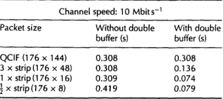
multiprocessor system for visual communications: W-J Duh et al. Overlapping ~ of communications. Although the hard- ware supported wormhole routing strategy ls'16 is good, it is not provided in the T800 transputer. In order to achieve higher communication efficiency, communication pipelin- ing is adopted. Each frame is chopped into small packets before transmission and each node uses double buffers to send/receive data. The experiment shows that a macro- block strip size is quite suitable for packetizing QCIF frames and the results are shown in Table 2.
Two categories of operations have been implemented in this system: the H.261 simulation and the fundamental video processing. The performance of each compression type defined in H.261 is measured and the comparisons are given in Table 3. In Table 3, the processing time is the total time needed to process one QCIF frame, and its reciprocal denotes the frame rate.
In Table 3, high efficiency is retained in most commonly used compression modes. As the number of node proces- sors increases, Tcomp decreases and Tcomm increases. Besides, the minimum grain size is problem dependent. For example, the macro-block is a basic processing unit in H.261, and decomposing the basic unit will introduce extra data communications and programming efforts. When porting the system to the Inmos T9000, it will work as a powerful dedicated compression chip which possesses the flexibility for developing new algorithms.
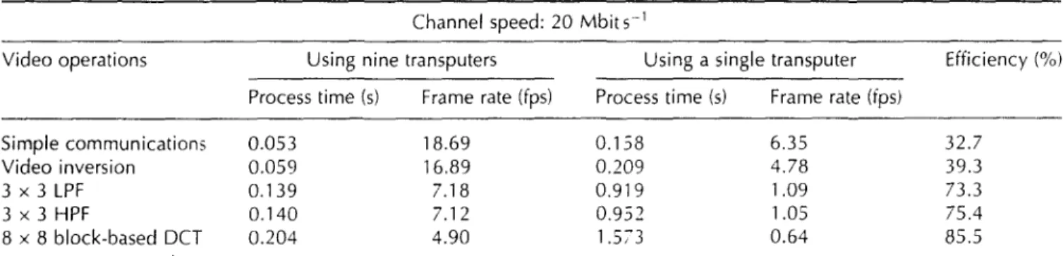
Table 4 gives the performance comparisons for video processing: 'Simple communication' indicates the set-up time (time to prepare the data for parallel processing) of the system; 'Video inversion' is simple subtraction, and the 3 x 3 HPF filtering is the fundamental operator in image processing. The kernel of 3 x 3 LPF is:
¼
(9)
A,
L 8 .Iand 3 x 3 is the discrete Laplace operator as:
[:i
-+ -']
8 -1 (10)-I -I
In Tables 3 and 4, as the operations become more compli- cated, the efficiency gets higher. The reason w h y the effi- ciencies of some modes are greater than 1 0 0 % is that the communication time for transmitting data to and from a single transputer is included. It is reasonable to treat the data transfer time, from/to the host, as the realistic I/0
Table 2 Total time for distributing/collecting a QCIF frame through nine transputers
Channel speed: 10 Mbits-;
Packet size Without double With double buffer (s) buffer (s)
QCIF (176 x 144) 0.308 0.308
3 x strip(176 x 48) 0.308 0.136 1 x strip (176 x 16) 0.309 0.074 ! x strip(176 x 8) 2 0.419 0.079
A m u l t i p r o c e s s o r s y s t e m f o r v i s u a l c o m m u n i c a t i o n s : W-J Dub et al.
Table 3 Comparison of the corresponding efficiency r'or H.261 simulation bet>,een nine tran-;puters and a single transputer
Channel speed: 20 Mbits 1
Compression type Using nine transputers Using a single transputer Efficiency ("4, Process time (s) Frame rate (fps) Process time (s) Frame rate (fps)
Intra mode 0.467 Inter mode 0.508 Inter + MC1 0.570 Inter + MC2 0.997 Inter + MC + FILl 0.61 7 Inter + MC ÷ FIL2 1.019 2.14 3.988 0.25 94.8 1.97 4.690 0.21 102.6 1.75 5.041 0.20 98.3 1.00 9.290 0.11 103.5 1.62 5.220 0.19 94.0 0.98 9.493 0.10 103.5 Intra mode : DCT
Inter mode : frame DPCM + DCT Inter + MC~ : motion ,.ector only
Inter + MC2 : motion ,.ector + frame DPCM + DCT Inter + MC + FlU : Inter-- MC1 + loop filter
Inter - MC - FIL: : Inter - ,"dC2 - loop filter
Table 4 Corresponding efficiencies of nine transputers versus a single transputer for video processing
Channel speed: 20 Mbits -1
Video operations Using nine transputers Using a single transputer Efficiency (%) Process time (s) Frame rate (fps) Process time (s) Frame rate (fps)
Simple communications 0.053 Video inversion 0.059 3 x 3 L P F 0.139 3 x 3 HPF 0.140 8 x 8 block-based DCT 0.204 18.69 0.158 6.35 32.7 16.89 0.209 4.78 39.3 7.18 0.919 1.09 73.3 7.12 0.952 1.05 75.4 4.90 1.573 0.64 85.5
constraints of devices. In the experiments, as the channel bandwidth increases, the efficiency increases.
In order to build a highly computationally efficient multiprocessor system, it is necessary to keep the ratio between communication and computation times high enough. The ratio is defined as
Tcomm (11)
;' -- Tcomp
Following Equation (1), the efficiency of the multiprocessor system can be approximated by:
efficiency ~ Tcomp
Ttota I
Tcomp (12)
Tcomm - Tcomp - ~z min(Tcomm , Tcomp)
AS Tcomm >~> Tcomp. ",'>> 1, t h e o v e r h e a d s o f t h e system
dominate the total processing time and thus the perfor- mance is poor. If the communication time and the compu- tation time are approximately equal, the performance of the system is controlled by the overlapping factor :~. When
Tcomm << Tcomp. ;' <~ 1. the efficiency approaches unity.
Therefore, given a 'real-time' constraint, say 2, the following condition must be satisfied:
Ttotal ~ £ (13)
Since Tcomp can be controlled by P, as P gets larger the performance of the system will be bounded by Tc .. . . .
DISCUSSION AND CONCLUSIONS
Designing efficient parallel programs in a loosely coupled multiprocessor environment is difficult since (1) no global timing is available in such an environment, (2) it is hard to analyse the behaviour of such systems, and (3) debugging in parallel programs is still a research topic. However, due to the regular data flow of video processing algorithms, designing its parallel programs is easier and the perfor- mance is fairly good.
A transputer-based multiprocessor system that simulates H.261 video compression and video processing is presented in this paper. There are nine node processors in the processor array. Three transputers are allocated for input buffers and three for output. By using input/output buffering, compatible I/O bandwidth are retained and large frame memories for storing video sequences are available.
Programming under the distributed computing environ- ments, such as in Reference 3, is easier than that of the TDS2 ~ 1. Under the former environment, there are powerful operating systems that handle the intensive communication and routing operations. The programmers just need to know the senders and the receivers without caring about any low level message communications. The programs developed under distributed computing environments can be ported to other distributed environments easily. However, with the additional real-time constraints, the simpler TDS2 is more flexible than powerful operating systems. Therefore, the program follows the data flow of the
A m u l t i p r o c e s s o r s y s t e m for visual c o m m u n i c a t i o n s : W-J Duh et al.
corresponding algorithm and makes full use of the power of the transputer array to the maximum extent. In our approach, the system is not only a highly efficient simula- tion system but also a powerful educational tool. Moreover, the configuration of the system can be modified dynami- cally to simulate various system topologies.
Geometrical decomposition of the image makes the parallel processing system very efficient. Every flame is evenly divided into nine horizontal strips of dimensions 176 x 16. Nine node transputers are allocated to process the strips. Each node processor holds three strips of the present frame and three strips of the previous frame. Henceforth, all data broadcasting and collections are completed during the loading phase and no communica- tions occur during the computing phase. High efficiency of the system is achieved by load balancing, computation/ communication overlapping and communication pipe- lining.
Communication overheads of the parallel system domi- nate the total processing time whenever the real-time constraint becomes more critical. Double buffering is a useful technique to alleviate the communication problem. Packet size is carefully chosen by consideration of each of programming and communication time. It is guaranteed that the real-time requirements of visual communication applications will be satisfied as long as the communication time is short enough.
The software simulation system is very flexible for system developers to use. New algorithms can be developed and verified quickly. The system is an efficient and near real- time simulation environment. It is also suitable for computer aided instruction (CAI) in teaching video signal processing.
ACKNOWLEDGEMENT
This research is supported by Computer and Communica- tion Lab. of ITRI under contract No. A0-80385.
REFERENCES
1 Draft Revision of Recommendation H.261, CCITT 5GXV, Document
584, Tokyo (November 1989)
2 Liou, M L 'Visual telephony as an ISDN application' IEEE Comm. Mag.
(February 1990)pp 390-38
3 Sijstermans, F and van der Meet, J 'CD-I full-motion video encoding on a parallel computer', Comm. ACM Vol 34 No 4 (April 1991) pp 82-91
4 Yu, L, Dub, W-J, Huang, J-H and Wu, J-L 'A real-time transputer-based visual phone simulation system' Proceeding of IEEE Workshop on Visual Signal Processing and Communication Taiwan (June 1991)
pp 120-123
5 Ahmed, N, Natarajan, T and Rao, K R 'Discrete cosine transform' IEEE Trans. Comput. Vol C-23 (January 1974) pp 90-93
6 Lee, B G "A new algorithm to compute the discrete cosine transform',
IEEE Trans. Acoust. Speech Sig. Proc. Vol 32 No 6 (December 1984)
pp 1243-1247
7 Hou, H S 'A fast recursive algorithm for computing the discrete cosine transform" IEEE Trans. Accoust. Speech Sig. Proc. (October 1987)
pp 1455-1462
8 Netravali, A N and Haskell, G Digital Pictures: Representations and Compression Plenum Press, NY (1988)
9 Transputer Technical Notes Inmos Limited. Prentice-Hail, Englewood
Cliffs. NI (1989~
10 Decegama. A L The Technology or" Parallel Processing and VLSI Hard- ware: Volume I Prentice-Hall, Englewood Cliffs, NJ (1989
1t Transputer Development System Inmos Limited, Prentice-Hall, Engle-
wood Cliffs, NJ (1988)
12 )ones, G and Goldsmith, M Programming on Occam2 Prentice-Hall,
Englewood Cliffs, NJ (1988)
13 Jain, J R and Jain, A K 'Displacement measurement and iLs application in interframe image coding' IEEE Trans. Comm. Vot 29 No 12
(December 1981 ) pp 1799-1808
14 Duh, W-J and Wu, J-L 'Parallel image and video coding schemes in multi-computers' IEEE Data Compression Conference (DCC '92), Snowbird, USA (March 1992)
t 5 Seitz, C 'The Cosmic Cube' Comm. ACM Vol 28 No 1 (January 1985)
pp 22-33
16 Zhang, X 'Systems effects of interprocessor communication latency in multicomputers' IEEE Micro Vol 11 No 2 (April 199!) pp 12-15,
pp 52-55
... Wei-Jou Duh was born in, Taipei, Taiwan, Republic of China, in 1956. He received a B5 degree in computer engineering from National Chiao-Tung University, Hsin-Chu, Taiwan, in 1987 and MS and PhD degrees from National Taiwan University, TaipeL Taiwan, in 1989 and 1992, respectively, both in computer science and information engineering.
He is now serving in the military. His research interests include fast algorithms and architec- tures in digital signal processing and the compression of digital images and video
]a-Ling Wu was born in Taipei, Taiwan, Republic of China, on November 24, 1956. He received a BS degree in electronics engineering from Tamkang University, Tamshoei, Taiwan, in 1979, and MS and PhD degrees in electrical engineering from Tatung Institute of Tech- nology, Taipei, Taiwan, in 1981 and 1986, respectively.
From August 1986 to July 1987 he was an Associate Professor in the Department of Elec- trical Engineering, Tatung Institute of Tech- nology. He became an Associate Professor at the Department of Computer Science and Information Engineering, National Taiwan University, in August 1987, and a Professor in August 1990. He currently teaches courses in digital signal processing, and data compression techniques and does research in the areas of signal processing, image/video coding, and neural networks.
networks, multimedia
Dr Huang is Professor of the Department of Computer Science and Information Engineering at National Taiwan University, Taipei, Taiwan. He received his B5 degree in electrical engi- neering from National Taiwan University in 1981 and his MS and PhD degrees in computer science from the University of California, Los Angeles in 1985 and 1988 respectively. He joined the faculty at National Taiwan University in 1988. His research interests include design and performance evaluation o/ high speed systems, and parallel and distributed systems.