A Survey and Comparison of Fault-Tolerant Optical Crossconnects
for All-Optical Networks
Chi-Yuan Chang, Chuan-Ching Sue, Sy-Yen Kuo (IEEE Fellow) Department of Electrical Engineering
National Taiwan University Taipei, Taiwan, R.O.C. [email protected]
Abstract
This paper surveys and compares a series of crossconnect architectures that supports fault tolerance and multicasting. First, a fault tolerant optical crossconnect (FTOXC) which can tolerate link, channel, and internal optical switch failures via spare optical channels, extra input/output (I/O) ports for an optical switch, and associated wavelength converters are introduced. Second, two different node architecture for multicasting and fault-tolerant optical crossconnect (MFOXC) are also presented for wavelength routed all-optical networks. Compared to the traditional optical crossconnect, They have the following two advantages: 1) the FTOXC node not only takes advantage of the power of wavelength conversion but also improves the capability of fault tolerance, and 2) the MFOXC node not only performs the multicasting efficiently but also improves the reliability significantly. They introduce a new feature (fault tolerance), keep the multicasting capability and can be used at some critical points in a network to improve the overall reliability and multicast performance. Furthermore, a fault tolerant wavelength routing algorithm (FTWRA) used in the normal/restored state is surveyed. The FTWRA can be applied to any all-optical network and can recover many types of failures. It can configure the number of working and spare channels in each output link based on the traffic demand. Finally, A global optimal setting of working and spare channels in each link can be found by formulating the problem as an integer linear program (ILP). The results show the number of working and spare channels in each link can be dynamically adjusted according to the traffic loads and the system reliability requirements.
Keywords: Wavelength Routing, Fault Tolerance, Multicast,
All-optical Networks, Wavelength Division Multiplexing, Integer linear program.
1 Introduction
As the internet traffic continues to increase exponentially, a wavelength division multiplexing (WDM) network with terabits per second per fiber becomes a natural choice as the backbone in the next generation optical internet. Advances in optical amplification and multiplexing technology also have resulted in the use of dense wavelength division multiplexing (DWDM) as a practical solution to the ever-increasing bandwidth demands across existing networks. The explosion of traffic is also forcing management of the core networks away from the DS3 levels and towards managing wavelengths within a DWDM environment. This results in the introduction of wavelength routed all-optical networks (WRAON) [1]. For a WRAON, circuit switching is preferred since the optical technology for implementing the intermediate node buffering, header recognition and processing, which are indispensable for packet switching networks, is not available yet [2-3]. The network element that can provide the required functionality within the core of the WRAON is an optical cross-connect (OXC) that is capable of 1)switching wavelengths with low latency, 2) performance monitoring, 3) Rapid provisioning and 4)Protection and restoration of lightpaths (end-to-end connections).
Fault-tolerance is one of the most important measures in optical Quality of Service (QoS). For a WRAON, network failures could interrupt a large number of communication sessions in progress, such as voice and data. As a result, the design of a WRAON must incorporate mechanisms to protect against potential failures, such as node failures, link failures, channel failures, and optical switch failures. Hence, in order to achieve protection against failures, spares must be provided for the corrupted traffic to be restored. It is also desirable that these failures should endeavor to be handled within the optical network layer, rather than by higher layers. With the advent of WDM techniques, it is possible to provide redundancy by means of spare wavelengths (channels) and switches. Several simple failure restoration techniques for WDM
mesh networks have been proposed in [4-10]. These researches all focus on designing failure restoration techniques, but without taking the OXC structure into consideration. On the other hand, the required number of wavelengths to guarantee a complete link failure restoration is often larger than that supported by technology. This situation becomes even worse in dynamic wavelength assignment where the connection is set up one by one. Although having multiple bi-directional links between each node pair can overcome the problem of insufficient number of wavelengths, the optical crossconnect will become more complex to handle the extra links and the cost of links will also increase. Therefore, we survey a fault -tolerant optical crossconnect architecture and the corresponding fault tolerant wavelength routing algorithm (FTWRA) under the current technology constraint of limited number of wavelengths and the assumption of a single bi-directional link between every node pair.
A fault tolerant OXC (FTOXC) consists of OXCs with and without wavelength conversion [1]. The fault tolerance capability of the FTOXC comes from the distributed optical switches in an OXC without conversion and the distributed converters in an OXC with conversion. With distributed optical switches, a single fault in an optical switch will not result in a fatal node fault and an optical switch does not need a large number of ports as an OXC with conversion. Using additional I/O ports in the optical switches and additional links and fixed converters between them, the failed lightpath can be restored by replacing the failed wavelength with a spare wavelength. In addition, FTWRA is a quasi-distributed dynamic routing scheme similar to that in [12]. The controller in each OXC communicates with other controllers by an in -band wavelength within the network for collecting information from the network and for finding the min-cost route either in the normal or faulty state.
On the other hand, multicasting (for one-to-many or many-to-many communications) is important and increasingly popular on the Internet (IP over WDM). For a WRAON, the optical crossconnect (OXC) plays an important role to realize switching. For WDM multicast, the optical switch needs to have the light splitting capability in order to be able to multicast data in the optical domain. To realize optical multicasting, one can utilize optical power splitters [11]. A power splitter is a passive device used to distribute the input signal to all outputs; thus providing multicasting in the optical domain without buffering. The inevitable power loss requires the deployment of amplifiers to compensate for the splitting loss. In addition, cross-connects which are able to satisfy all the different multicast demands must be equipped with a splitter for every wavelength on every input fiber link.
Several OXC structures where proposed to support multicasting [13-16]. Five classes of multicasting OXC exist. First, a star coupler that has inherent multicasting capability is used to construct a class of OXC [13]. But wavelength converters and tunable filters are required to work in a large wavelength range. Second, two stage splitters and one-stage combiners are used to construct another class of OXCs [13,14]. Third, a splitter-combiner switch that has inherent multicasting capability is employed to construct another class of OXC [12]. Fourth, a splitter-and-delivery switch (SaD) is proposed to build OXCs [15]. Fifth, a Tap-and-Continue switch (TaC) [16] is also built to form OXCs with zero power splitter. All these OXCs support multicasting. Note that switches with splitting capability are usually more expensive to build than those without. Due to this reason, many researchers selectively let the switches in a network have splitting capability [17], which means that only a subset of the switches in a WDM network supports light splitting. These researches all focus on designing an OXC with multicasting capability, but without fault tolerance. Therefore, we will compare two multicasting and fault-tolerant optical crossconnect (MFOXC) architecture by considered with different respects in terms of modularity, fanout capability and power distribution.
The rest of this paper is organized as follows. Section 2 surveys the basic architecture of the FTOXC and MFOXC and compares them in terms of modularity, fanout capability, and power distribution among the different architectures. Section 3 surveys the failure restoration schemes for different fault scenarios. Section 4 describes the FTWRA and shows the results. Section 5 concludes this paper.
2 Highly Reliable Node Architecture
2.1 Network Architecture
Figure 1 shows a WDM all -optical network employing wavelength routing, which consists of OXCs interconnected by optical links. Each OXC node includes a workstation (A, B,..., E) and an optical switch (1, 2, … ,5). Each link is assumed to be bidirectional and consists of a pair of unidirectional physical links.
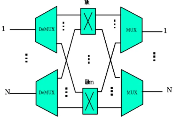
An optical crossconnect is a device capable of routing a wavelength on an input link to any output link. However, two input links with the same wavelength cannot be routed simultaneously onto an output link, e.g. the link from node 4 to node 3 in Figure 1. If there are m wavelengths on each link, the OXC may be viewed as consisting of m independent optical switches, one for each wavelength as shown in Figure 2. Each optical switch has
N inputs and N outputs where N is the number of input/output links. There are no optical-to-electrical (O/E) and electrical-to-optical (E/O) conversions, and hence no buffering is needed at the intermediate nodes in these all-optical networks.
The effect of wavelength converters on the signal quality bas been investigated by adding converters to the OXC. Wavelength converters are often desired in the OXC to make the network management much easier and reduce the blocking probability because of their signal regeneration and noise reduction capabilities [18-20]. Figure 3 shows an OXC with wavelength converters. The drawbacks of the wavelength converter include not only the added higher cost and complexity to the system, but also the single fault problem. If the central optical switch is faulty, the whole OXC will fail if no redundancy is provided at the node level. In addition, the crosstalk problem can be serious if the tuning range for wavelength or the number of wavelengths is large. These will result in the system unreliable. In contrast the OXC without converters in Figure 2 can tolerate a single fault in an optical switch. This is because any nonfaulty optical switch can replace a faulty optical switch and the resulting OXC can still be functioning with all the wavelengths except the wavelength used by the faulty optical switch.
As for fault tolerance capability, an OXC without converters is superior to an OXC with converters. But for network performance (in terms of wavelength reuse), the reverse is true. Hence fo r a highly reliable FTOXC/MFOXC and for good performance in the system, we survey and compare the node architecture either with some fixed wavelength converters or with no wavelength converters. The former is for the design of FTOXC the latter is for the MFOXC.
2.2 NODE ARCHITECTURE FOR FTOXC
The FTOXC is an OXC, which uses wavelength-dependent optical switches and fixed wavelength converters. Each optical switch is extended with m-1 additional ports and corresponding wavelength converters to connect to the other m-1 optical switches. The resulting FTOXC has n optical switches with (m+n -1) inputs and (m+n-1) outputs as compared to n inputs and n outputs in Figure 2, and m (m -1) converters as compared to m ⋅n converters in Figure 3.
An all optical FTOXC can be readily implemented. For example, an optical switch may consist of a few 2-by-2 directional couplers. Switching is accomplished by properly adjusting the signal-coupling ratio of these 2-by-2 couplers. The wavelength conversion is to employ either absorption saturation of a semiconductor laser diode, four-wave mixing, or gain saturation of an optical amplifier [21]. Furthermore, the optical loss is assumed to be compensated with optical amplifiers (e.g. EDFA (Erbium Doped Fiber Amplifiers) or SOA (Semiconductor Optical Amplifiers)) properly located in the FTOXC. The FTOXC introduces a new feature (fault tolerance) and keeps the convertibility feature. The converters can be further grouped into m banks with each bank containing m-1 fixed converters as shown in Figure 4(b). An additional switch can be placed in each converter bank to mask wavelength converter faults, but this causes additional power consumption which spoils the transparent OXC1 A OXC2 B OXC3 C OXC4 D OXC5 E 1 λ on
lightpath lightpath onλ then1 λ2 1 λ 1 λ 1 λ 2 λ
Figure 1 A WDM network with OXCs interconnected by fiber links.
1 N 1 N λ1 λm MUX DeMUX MUX DeMUX 1 N 1 N λ1 λm
Figure 2 An OXC without wavelength converters.
1 N 1 N λ1 λm SD λ 1 N 1 N λ1 λm λ Converter
property [22]. The architecture proposed in [21] must incorporate additional switches to share converters per link or per node, and the transmission effect may be serious to offset the advantage of reduced cost. Thus, in the FTOXC, there is no additional switch for wavelength converters. However, it is possible that the lightpath may go through multiple hops between multiple optical switches in the OXC. That is, if more than one lightpath entering the same optical switch need to be converted to the same wavelength, they can not be transferred to the same optical switch because there is only one link between these two optical switches. The lightpaths that can not be transferred immediately are called the conflicting lightpaths. The conflicting lightpaths must go through other free interconnecting links and optical switches to the desired optical switch in the OXC. Thus, the signal degradation may be serious even without additional switches as in [23] since there is a fixed wavelength converter in each hop. Hence, the FTWRA uses the parameters f and g to take this transmission effect into account. From this viewpoint, the control in FTOXC is more complex. When the connection is determined from the FTWRA, the controller must find the proper multiple-hop route within the OXC if there are conflicting lightpaths. In Figure 4(c), one example is provided to explain how a proper route is found. There exist two lightpaths: one is shown by a bold line from I1 to O1, and
the other is shown by a dashed line from I2 to O2. These
two lightpaths entering the same optical switch λ1 can be
transferred to the same optical switch λ2 because the
dashed lightpath goes through the optical switch λ3 and
then to the optical switch λ2. By proper control in the
FTOXC, the conflicting lightpaths can successfully progress without the constraint that only one link exists between the optical switches λ1 and λ2.
The fault tolerance capability of the FTOXC comes from the (m)⋅(m -1) wavelength converters. The number of wavelength converters wasted is S/mwhen the FTOXC has only one output link and the designated number of spares is S. The number S/ m can be reduced when an FTOXC has more than one output link and the contents of the designated spares in each output link are different. In the extreme case, when there are i output links in an FTOXC and the designated spares in each output link is Si
such that ∪Si = m, the number of wavelength converters
wasted is zero because all the converters are used for the working channels in all output links. All the details can be found in [24].
2.3 NODE ARCHITECTURE FOR MFOXC
In this session we survey and compare two different types of MFOXC to support multicast and fault tolerant
[25,26]. The MFOXC based on the OXC structure without wavelength conversion gains high reliable structure and supports multicast. Hence the node structure for MFOXC is different from that of FTOXC. The MFOXC is divided into two different structures. One is Tap-base MFOXC which is implemented by a set of Tap-and-Continue Modules . The other is splitter-base MFOXC which is designed by a series of splitters. These MFOXC nodes not only performs the multicasting efficiently but also improves the reliability significantly.
2.3.1 Tap-based MFOXC
Figure 5 shows an implementation of an N×N
tap-based MFOXC. The tap-based MFOXC is an OXC
1 N 1 N λ1 λm MUX DeMUX MUX DeMUX 1 N 1 λ1 λm λ1 λ1 λm-1 λ2 λ3 Wavelength converter λ ... λ1 λλm λ ... λ1 λλm λ ... λ1 λλm λ ... λ1 λλm (a)
...
...
...
...
λ1 λ1 λ2 λΛ λ1 bank...
...
...
λΛ λΛ λ1 λΛ−1 λΛ bank (b) λ1 λ2 λ3 λ1 λ2 λ1 λ2 FTOXC I1 I2 O1 O2 (c)Figure 4 (a) Structure of FTOXC (b) Wavelength converter bank (c) Example routing determination.
with multicasting and fault tolerance capability, which uses wavelength-dependent optical switches (or mechanical switches). It uses a set of Tap-and-Continue Modules (TCMs) on the right side of Figure 5(a). In the TCM 1 shown in Figure 5(b), an extremely small fraction of the input signal Pin(e.g., (1/1000) Pin) is tapped and forwarded
to the local station. The remaining power of the order of 99.9% is switched to the other (N−1) outputs. To switch the signal to any of the (N−1) outputs, Figure 5(c) shows that the tapping devices (Tap) are used to implement the TCM4. A 1×N TCM module has
log2N
stages where stage i has twice the number of Taps compared to stage (i-1). Figure 5(d) shows an example of TCM 8. An input signal is tapped in using a tapping device. By controlling the voltage on these Taps, an input can be connected to any output port(s). Hence, the TCM 8 module can support multicasting traffic in the optical domain by controlling the voltage on these Taps. For example, a multicasting session with destinations 1,4 and 5 shown in Figure 5(d) can be achieved by controlling the voltage on TCM1 and TCM4. The destinations 1,4 and 5 has signal power distribution 25%, 25% and 50%, respectively and all other nodes have no power consumption. Therefore, this architecture saves extra power consumption when a node is not a destination.On the other hand, the 2×1 SW element shown in Figure 5(b) and the 3×1 SW element shown in the right side of Figure 5(a) are used to select the alternative port of switch for normal operation, fault tolerance, or multicasting. If the normal switch is faulty, by controlling the taps, the signal power is directed toward the fault tolerant switch. Because this behavior occurs in the optical domain, no other restoration in the higher level needs to be considered. It is also desirable that failures should endeavor to be handled within the optical network layer, rather than by higher layers. In addition to routing and switching signals, the MFOXC also serves as a source and sink of traffic in the network by an array of multi-wavelength transmitters and an array of multi-wavelength receivers, respectively. The source (sink) is the start (end) of a connection. Each inbound link and outbound link has its associated receiver (Rx) and transmitter (Tx), respectively. The bottom of Figure 5(a) shows that each Tx or Rx is realized by an array of multi-wavelength transmitters or an array of multi-wavelength receivers, respectively. Each optical switch is extended with 1 additional port to support inbound link and outbound link for multicast. The resulting MFOXC has 2N optical/mechanical switches with (N+1) inputs and (N+1) outputs as compared to N inputs and N outputs in Figure 2.
2.3.2 Splitter-based MFOXC
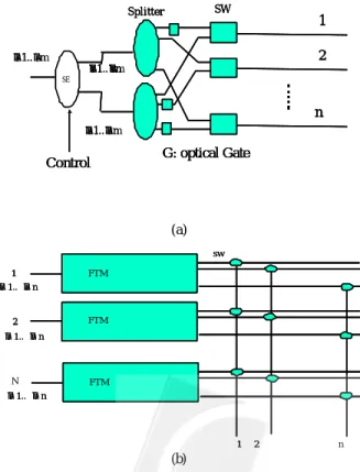
The Splitter-and-Delivery (SaD) is a cross-connect with multicast capability that was proposed in [15]. A cross-connect consists of a set of SaD switches (see Figure 6(a)) for each wavelength. A SaD switch consists of an interconnection of power splitters, optical gates (to reduce the excessive crosstalk), and photonic switches. Figure 6(b) shows the organization of a cross-connect based on the SaD switch. In addition to the SaD switches,
N 1 N DeMUX Mux Mux 1 1 N 3x1 sw Tx Rx TCM8 TCM8 λm λ1 TAP TAP TAP TAP 1 N+1 1 N N+1 m λ λ1⋅⋅⋅ λ1⋅⋅⋅λm m λ λ1⋅⋅⋅ m λ λ1 ⋅⋅⋅ m λ λ1⋅⋅⋅ m λ λ1 ⋅⋅⋅ ⋅ ⋅ ⋅ ⋅ ⋅ ⋅ 1 λ m λ m λ 1 λ Μ Μ Μ Μ Μ Μ Μ Μ Μ Μ Μ Μ Μ Μ Μ Μ Μ Μ Μ Μ DeMUX main-module (a) 1 2 IN1 IN2 T A P TAP To Local Station 0.5% of Input 99.5% of Input TCM1 SW (b) TAP TAP TAP TCM4 (c) TCM1 TCM4 TCM4 1 ... 4 5 ... 8
IN1
IN2
TCM8
(d)Figure 5 (a) Structure of a tap-based MFOXC, (b) TCM1 module, (c) TCM4 module, (d) TCM8 (with
N
2
demultiplexers (multiplexers) are used to extract (combine) individual wavelengths. In the following we will review the structure of splitter-based MFOXC.
Figure 7 shows an implementation of an N×N
splitter-based M FOXC. Its architecture is based on the SaD switch. In order to achieve robustness on the splitter for reliability, a duplicated splitter is used on each SaD switch. In Figure 7(a) a fault tolerant and multicasting (FTM) module is introducted. The input lightbeam is initially transferred to one of the branches by controlling the SE. Each branch is split into n branches and connects to a switch. Hence, any input of the splitter can be connected to any output branch. Figure 7(b) is a switch module equipped with N FTM modules and 2×1 switches. Each branch is switchable to an associated output by a 1×2 switch. Therefore, any input can be connected to none, one, several or all the output ports. This features a multicasting capability.
To implement the FTM module, four types of components, i.e., 2 splitters, optical gates, 2×1 SW, and a
2
1× SE are integrated on a silicon board using planar silica waveguide technology [27-29]. The structure shown
in Figure 7(b) not only has the advantage of integration for mass production, but also supports the modularity of splitter-based MFOXC.
2.3.3 Further Discussion for MFOXC
In this section, we compare with the multicast parameters in terms of modula rity, fanout capability, and power distribution between the tap-based MFOXC and the splitter-based MFOXC.
(1) Modularity and Expansion
Modularity: It is desirable that an MFOXC has modular structure and is expandable to allow new fibers (fiber modular) and wavelengths (wavelength modular) to be added to keep pace with the future evolution for the multiwavelength optical transport network. There are two kinds of expanding methods. One is to increase the number of fibers and wavelengths only by a few. The expanding method is straightforward without changing the layout of the original MFOXC’s. Large scale devices, e.g., (N+N1) x (m+m1) switch and (m+m1) x 1 multiplexer are used as anticipated. The other is that the number of wavelengths and fibers are increased significantly. Take Figure 8(a) for example. If N is expanded by K times, where K is an integer, the original MFOXC is consider as a main module (as shown in Figure 5(a)). K main modules are connected by a common junction [23]. On the other hand, if the fiber bandwidth is increased by K times, it is obvious that the channel spacing will become denser. The original multiplexers must be replaced. The remainder of the original MFOXC is unchanged and regarded as a main Splitter Gate Switch
1 2 N 1 2 N Amplifier Bank Μ Μ Μ Μ Μ Μ Μ Μ Λ (a) 1 N 1 N λ1 λm MUX DeMUX MUX DeMUX 1 N 1 N λ1 λm SaD (b)
Figure 6 (a) an SaD switch, (b) an N×N optical cross-connect based on the SaD
1 2 n SW Splitter λ1..λn λ1..λn G: optical Gate Control λ1..λn 1 2 n SW Splitter λ1..λn λ1..λm G: optical Gate Control λ1..λm 1 2 n SW Splitter λ1..λm λ1..λ G: optical Gate SE Control λ1.. (a) FTM FTM FTM 1 2 1 2 n λ1..λn λ1.. λn λ1..λn sw FTM FTM FTM 1 2 1 2 FTM FTM FTM FTM FTM FTM 1 2 N 1 2 λ1..λn λ1.. λn λ1..λn sw (b)
module. K main modules are connected together by the new multiplexers and 1xK splitters, as shown in Figure 8(b). All the expanding operations as described above do not reduce the multicasting capability of an MFOXC.
(2) Multicast Fanout expansion:
Tap-based MFOXC: Figure5(c) shows the tapping devices (Tap) are used to implement TCM4 to support multicast. A 1×N TCM module has
log2N
stages where stage i has twice the number of Taps as stage (i-1). Hence a 1×N×K TCM module has only
log2NK
stages. The expanding method is straightforward without changing the layout of the original architecture. Larger scale device switch and multiplexer are used.
(3) Power distribution:
Power is one of the most important quantitative measures in optical networks. For successful deployment of optical networks this measure needs to be considered at the design phase.
A.Tap-based MFOXC:
Figure 5(d) shows an example TCM 8. An input signal is tapped in using a tapping device. A small fraction of the signal power is directed toward the local station, while the rest continues to a multistage network of Taps. By controlling the voltage on these Taps, an input can be connected to any output port(s). Hence, the TCM8 module can support multicasting traffic in the optical domain by controlling the voltage on these Taps. For a multicasting session with k destinations (k<N), it can be achieved by controlling the voltage on the TCM1 and TCM4. The k destinations have at least 1/k signal power distribution and the other nodes do not have any power consumption. For example, a multicast session with destinations 1,4 and 5 has signal power distribution 25%, 25% and 50%, respectively (fanout = 8). Hence, this architecture can be easily cascaded without extra optical power amplifiers by designing the network topology appropriately.
B.Splitter-based MFOXC:
The power splitter is a passive device used to distribute the input signal to all outputs. Hence, for a multicast request in MFOXC, all the outputs have the same power distribution. In other words, the power loss depends on the fanout of a splitter instead of a multicast group. For example, a multicast session with destinations 1,4 and 5 has the same signal power distribution 12.5% (fanout = 8). Compared with the tap-based MFOXC mentioned above, the cascading capability is poor.
3 Fault model and Failure Restoration
3.1 Fault model
Many physical level protection and/or restoration schemes were proposed for wavelength routing networks (see [30-32] for a survey). They always rely on the presence of spare resources in the network that are used to restore disrupted lightpaths. Many possible physical faults in a WRAON are depicted in [33,34]. Similar to previous researches this paper only consider failures in the active comp onents of the FTOXC and the fibers, and assume that the passive components of the FTOXC and some critical components (e.g. SE, tap) of the MFOXC are reliable. The fault model is in the following:
(1) Channel fault: This fault can result from the failure o f a designated transmitter or receiver for a wavelength. In this case, only the failed wavelength on a link between two OXCs can not be used for transmission and other wavelengths still work.
KN 1 De MUX Mux Mux 1 1 m λ λ1⋅⋅⋅ m λ λ1⋅⋅⋅ m λ λ1⋅⋅⋅ λ1⋅ ⋅⋅λm
Μ
Μ
De MUX Main Module 1 Main Module 2 Main Module KΜ
Μ
Μ
Μ
Μ
KN 1xKm Kmx1 (a) N 1 De MUX 1 1 kmλ
λ
1⋅
⋅⋅
Μ
Μ
De MUX MFOXC1 MFOXC 2 MFOXC KΜ
Μ
Μ
Μ
Μ
N 1xK splitter Kmx1 m λ λ1 ⋅⋅⋅ m m1 λ2 λ+ ⋅⋅⋅ km m k λ λ(−1)+1⋅⋅⋅ kmλ
λ
1⋅
⋅⋅
λ
1⋅
⋅⋅
λ
km kmλ
λ
1⋅
⋅⋅
(b)Figure 8 (a) Expanding method to increase the number of fibers by K times. (b) Expanding method to increase the number of wavelengths by K
(2) Link fault: This is typically caused by a fiber cut or an optical amplifier fault. The channel faults in a link can also be emulated as a link fault if the number of failed channels exceeds a threshold. Further, single link fault is assumed.
(3) Optical switch fault: This is due to the failure of the power circuit. The failed optical switch also results in the failure of the corresponding channel on all the associated input and output links of the OXC and the corresponding wavelength converter bank in the FTOXC. Such failure can not be locally restored because the failed path can not use the converters behind the failed optical switch.
(4) Wavelength converter fault: This is also due to the failures of filters or power circuit. This fault changes the conversion capability of the FTOXC from full to limited.
(5) Node fault: This is the most severe fault, and may result from the power outage of the controller in the FTOXC. The optical switch faults in a FTOXC or MFOXC can also be emulated as a node fault if the number of failed optical switches is over some threshold. This failed node will not be able to accept new call requests. The lightpaths passing through the failed FTOXC or MFOXC need to be restored.
3.2 Failure Restoration
In this section, we survey how the FTOXCs/MFOXCs can be reconfigured to tolerate the modeled faults and then give an example to compare with each case. Assume that the fault detection mechanism in [33,34] is adopted in the FTOXC/MFOXC because it can differentiate between a node fault and a link fault. The restoration scheme has two phas es: one is link-based and the other source-based. The link-based restoration basically means that only the FTOXCs/MFOXC connected to the failed components are involved in the restoration process and the original lightpath is not dropped and reestablished. The source-based restoration means that the original lightpath is entirely dropped and a new lightpath is reestablished from the source node due to insufficient spare channels.
A.Channel faults
The least cost solution for channel faults is to allocate some channels on each link between FTOXCs/MFOXC as spare channels. Firstly, we take the FTOXC as an example to show how the restoration process is. The restoration procedure of channel fault for MFOXC is the same as that for FTOXC. Upon detection of a channel failure, the controller in the FTOXC redirects the lightpath from the failed channel to the spare channel. This solution can be extended to tolerate multiple channel
failures if there is more than one spare channel. If the number of spare channels is insufficient, the multiple channel faults can be divided into two classes. One class is handled by the link-based restoration, which still uses the spare channels. The other is by the source-based restoration that reestablishes the restoration path from the source node. Another possible solution, which is not included in our mechanism, is to use the method for link fault. The restoration scheme is shown in Figure 9. It only shows the restoration from a single channel fault. The channels C and C’ are working channels. The channels S and S’ are spare channels in FTOXC A and B, respectively. Note that the spare channel needs not be the same between the end nodes of the failed link. Upon detection of channel C failure in link L, the controller in FTOXC node A informs node B that the spare channel is S. Then FTOXC A configures the optical switch C to transfer the lightpath to the optical switch S and configures the optical switch S to transfer the lightpath to the original link L. When FTOXC B is informed of a channel fault and the corresponding spare channel, it configures the optical switch S to transfer the lightpath to the optical switch S’ and configures the optical switch C’ to transfer the lightpath from the optical switch S’ to the original channel.
In this case, each lightpath recovered by the link-based restoration goes through at most one additional switch/converter in the FTOXC before the failed link and at most two additional switches/converters in the FTOXC after the failed link. In addition, node A needs to inform node B which spare channel (S) it should use to restore the failed channel C. Thus, coordination is required between nodes A and B.
B.Link fault
B.1. Link fault for FTOXC
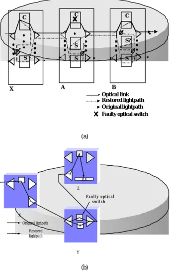
We can use the line protection method to repair the lightpaths affected by a single link fault locally with the designated spare channels. Take for example the lightpath in Figure 10(a). The original normal lightpath is from the source node to X, then to Z, and finally to the
S S C C’ Failed channel A B Optical link L Restored lightpath Original lightpath C S
...
...
...
...
.
.
.
C ... S’destination node. Assume there is a link fault between nodes X and Z. After detecting the failure, this lightpath must be able to re-route around the failed link. In our link-based restoration mechanism, the controller in node X informs node Y the spare channel is S and the restoration path is X-Y-Z, and configures the optical switch C to re-route the failed lightpath to the spare channel S. The link-based restoration path is determined in advance based on the shortest path on the network without the failed link. The controller in node Y informs the successor node Z (Z is the other end node of the failed link) in the restoration path that the spare channel is S’ and the restoration path is Y-Z. It also informs node X that it has agreed on this restoration. Note that the spare channel needs not to be the same along the restoration path. If the restoration path stored in node X can not afford to restore the failed lightpath due to insufficient spare channels, the source-based restoration is performed and the original path is given up.
In this case, each lightpath recovered by the link-based restoration goes through at most one additional switch/converter in the FTOXC before the failed link, at most two switches/converters in the FTOXCs along the link-based restoration path, and at
most two additional switches/converters after the failed link. Besides, coordination is required between the neighbor nodes along the restoration path to get the information of spare channels.
B.2. Link fault for MFOXC
Take for example the lightpath in Figure 10(b), the original normal lightpath is from the source node to X and finally to the destination node Z. Assume there is a link fault between nodes X and Z. After detecting the failure, this lightpath must be able to re-route around the failed link. The controller in node X informs node Y the spare channel and the restoration path is X-Y-Z, and configures the optical switch in X to re -route the failed lightpath. The link-based restoration path is determined in advance based on the shortest path on the network without the failed link. The controller in node Y informs the successor node Z (Z is the other end node of the failed link) in the restoration path and the restoration path is Y-Z. It also informs node X that it has agreed on this restoration. If the restoration path stored in node X can not afford to restore the failed lightpath due to insufficient spare channels, the source-based restoration is performed and the original path is given up.
C.Optical switch fault
Upon detecting failure of the optical switch, an example restoration route is shown in Figure 11.
C.1. Optical switch fault for FTOXC
This example shows that when an optical switch fails and there is an active lightpath passing through it, how the link-based restoration is performed. In Figure 11(a), if the optical switch C within node A fails, node A informs the predecessor node X and the successor node B in the original path that the optical switch C has failed and informs the successor node B that spare channel S’ is used. The node X also needs to tell the successor node A that the spare channel S has been used. When there is more than one active lightpath passing through the failed switch or more than one optical switch failure, the solution is also similar. Furthermore, when the link-bas ed restoration can not be applied to the failed lightpaths due to insufficient spare channels, the source node performs the source-based restoration to reestablish new lightpaths and the original lightpath is abandoned.
In this case, each lightpath recovered by the link-based restoration goes through at most one additional switch/converter in a predecessor FTOXC, at most two additional switches/converters in the current FTOXC, and at most two additional switches/converters in a successor FTOXC. Coordination in the link-based restoration is always necessary to properly use the specified spare channel among the predecessor (X), current (A) and successor (B) nodes.
S C S’ C S’’ C X Y Z L i n k F a i l Optical link Restored lightpath Original lightpath S S’ (a) X Y Z RX Original lighpath Restored lightpath F a i l e d l i n k (b)
Figure 10 Restoration from a link fault using a spare channel for (a)FTOXC and (b) MFOXC
C.2. Optical switch fault for MFOXC
Upon detecting failure of the optical switch (mechanical switch), an example restoration route is shown in Figure 11(b). This example shows that when an optical switch fails and there is an active lightpath passing through it, how the link-based restoration is performed. In Figure 11(b), if the switch within node Y fails, node Y uses the spare switch S to operate. In this situation node Y needs not inform any other nodes in the path. When there is more than one active lightpath passing through the failed switch or more than one optical switch failure, the solution is also similar.
D.Wavelength converter fault
Owing to MFOXC without wavelength conversion, the wavelength converter fault only occurs in FTOXC structure. An example restoration scheme is shown in Figure 12. This is similar to the case of channel fault. The difference is that the channel fault induced by a converter fault is meaningful only to the lightpath utilizing it. Another lightpath has no corresponding channel fault. For example, the converter λC-λD fault is a dual of the channel D fault in the link A-B for the lightpath passing it,
but the other lightpath can still use the channel D in the link A-B as long as this lightpath is not using the optical switch C.
In this case, each channel recovered by the link-based restoration goes through at most two additional switches/converters in the successor FTOXC. The coordination in the link-based restoration is only performed by node A to indicate node B that the spare channel S has been used.
E.FTOXC node fault
E.1. Node fault for FTOXC
Due to the high cost of a complete spare node, the FTOXC do not suggest sparing at the node level. It is possible for us to record the node-based restoration path in each node, which is similar to the link-based path and can be found from the shortest path in the network without the failed node and the associated links. It is not realistic to consider this rare fault because the number of affected lightpaths can easily exceed the number of spare channels in the node-based restoration path. The number of restoration paths needs to be stored may be too high. Instead, our survey is to use the source-based restoration for node faults.
Indeed, there are many possible routes for the restored lightpath as long as it is not conflicting with other working lightpaths. In the Figure 9, 10, 11 and 12, the restored lightpath choose the indirect route, for example, in the FTOXC-B of Figure 9, the restored lightpath entering the switch S is transferred to the switch S’, then goes to the switch C’. It can also choose the direct route t hat the restored lightpath directly goes to the switch C’ from S. Why we choose the indirect route to present our fault restoration mechanism is to calculate the maximal hops used within the FTOXC. The direct route as the above can be also well in Figure 9, 12, the FTOXC-Z of Figure 10 and the FTOXC-B of Figure 11 except in the FTOXC-Y of Figure 12 and the
S C S } C A B S C X Optical link Restored lightpath Original lightpath Faulty optical switch
S } S? (a) X Y Z RX Original lighpath Restored lightpath F a u l t y o p t i c a l s w i t c h S (b)
Figure 11 Restoration from an optical switch fault for (a)FTOXC and (b) MFOXC. S C A S D B D Optical link Restored lightpath Original lightpath Faulty wavelength converter
S ’
...
...
...
...
...
...
FTOXC-A of Figure 11. The exception is due to the fact that the restored lightpath must use the spare channel S in the output link of FTOXC-Y in Figure 10 and the spare channel S’ in the output link of FTOXC-A in Figure 11. Furthermore, since the channel S’ is a spare channel in the output link, the links connecting from other optical switches including optical switch S to the optical switch S’ must be guaranteed to be idle all the time.
E.2. Node fault for MFOXC
The optical switch faults in a MFOXC can also be considered as a node fault if the number of failed switches exceeds some threshold. However, in the MFOXC, all the switches have spare ones to recover switch faults. The MFOXC node fault can be handled by the mechanism for switch fault.
4 Fault Tolerant Algorithm and Result
4.1 Fault Tolerant Wavelength Routing Algorithm
The algorithm calculates the cost of routing as the sum of individual cost for using channels in links and wavelength converters. This is because using a channel will reduce the available bandwidth, thereby increase the potential to block future calls, and using a wavelength converter will reduce the number of available converters behind each optical switch and increase the potential to block future calls which need the converters. Then an auxiliary graph is generated for the representation of conversion cost and channel cost.
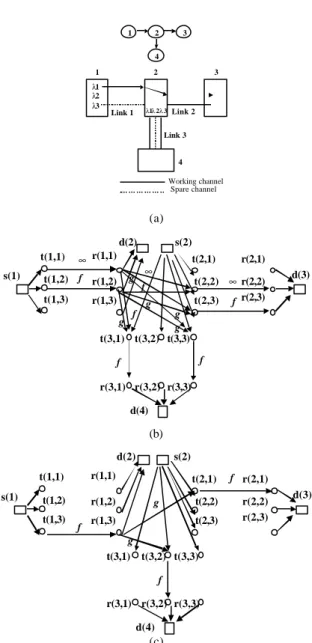
An example is shown in Figure 13. In Figure 13(a), the original network has a spare channel λ3 in Link 1, a spare channel λ1 in Link 2 and a spare channel λ2 in Link 3. The lightpath is node 1 to node 3 using λ1 in Link 1 and λ2 in Link 2. The ordinary route mode and the source-restoration route mode are shown in Figure 13(b) and Figure 13(c), respectively. In Figure 13(b), the weights of the channel edges (t(1,1), r(1,1)), (t(2,2), r(2,2)) and the working-converter edge (r(1,1), t(2,2)) are set to ∞ to indicate the occupation by an existing lightpath. The weights of the edges (t(1,2), r(1,2)), (r(1,2), t(2,2)), (t(2,3), r(2,3)), (r(1,1), t(3,1)), (t(3,1), r(3,1)), and (t(3,3), r(3,3)) are set to a finite positive value f and the weights of edges (r(1,1), t(2,3)), (r(1,2), t(2,3)), (r(1,2), t(3,1)), (r(1,2), t(3,3)) and (r(1,1), t(3,3)) are set to a finite positive value g. Other edges with weights equal to infinity are excluded from the graph to simplify the graph representation. As for edges with no weight assigned, they are assumed to have zero weights. Similarly, the restoration-routing mode is shown in Figure 9(c) with the same labeling rule. In Figure 13(c), the weights of the edges (t(1,3), r(1,3)), (t(2,1), r(2,1)), and (t(3,2), r(3,2)) are set to a finite positive value f and the weights of edges (r(1,3), t(2,1)) and (r(1,3), t(3,2)) are set to a finite positive value g. Other edges with weights equal to infinity are excluded from the graph to simplify the graph representation.
The restoration path stored in the FTOXC is found from the G(N , L) not from G(V, E, C) when the link-based restoration is performed. That is, only the path information is stored and it does not matter which channel is used to restore the path. This restoration path is stored only for faster restoration when a link fault has occurred. The ordinary routing path is found from the G(V, E, C) obtained from the ordinary routing mode. And the source-based restoration path for each fault can also be found from the G(V, E, C) obtained from the restoration routing mode. The transmission effect discussed in [35] can also be considered in the FTWRA by adjusting the
Working channel Spare channel 1 2 3 λ1 λ2 λ3 Link 1 Link 2 4 λ1 λ 3λ 2 Link 3 1 2 3 4 (a) s(1) t(1,1) t(1,2) t(1,3) r(1,1) r(1,2) r(1,3) t(2,1) t(2,2) t(2,3) r(2,1) r(2,2) r(2,3) d(2) s(2) ∞ ∞ ∞ d(3) f g f g f d(4) t(3,1) t(3,2) t(3,3) r(3,1) r(3,2) r(3,3) f g g g f f (b) s(1) t(1,1) t(1,2) t(1,3) r(1,1) r(1,2) r(1,3) t(2,1) t(2,2) t(2,3) r(2,1) r(2,2) r(2,3) d(3) d(2) s(2) f g f g d(4) t(3,1) t(3,2) t(3,3) r(3,1) r(3,2) r(3,3) f (c)
Figure 13 (a) Original network. (b) Graph for the ordinary routing. (c) Graph for the restoration routing.
values of f and g. As for the link-based routing path, the number of traversed converters must be coordinated between the participating nodes. The weighting function can be selected carefully to achieve better channel utilization. For example, the weight c(l,λ) of each working channel edge (t(l,λ), r(l,λ)) can be determined based on the number of working lightpaths (pi) mod the
number of wavelengths Λ, i.e., c(l,λ)= pi if Ci = 0, 1/Ci if Ci ≠ 0 where Ci ≡ pi mod Λ. Using this formula, we can
always select the link with least load link to achieve load balance in the network.
A shortest-path algorithm, e.g., Dijkstra’s algorithm, can derive the route for the above two modes. If there is a tie during the search, the algorithm will pick the path with the smallest index of channel on the smallest index of link. This ensures that a wavelength with higher index will not be used unless it is necessary, thereby conserve wavelength resources. If a path can not be found, the request is blocked.
4.2 Experimental Results
In this section, some of the experimental results for the FTOXC structures are introduced. The details can be found in [24]. The global optimization is performed only under the assumption of a single link fault. The objective of the global optimization is to optimally allocate an optimal number of working (spare) channels when there is a single link fault and the link-based restoration is performed. We use the integer linear programming (ILP) [37] to analyze this optimization problem. A local optimization method to find the number of working channels is proposed to reduce the high complexity of the global optimization.
There are four real sparse networks: ARPANet, UKNet, EON, and NSFNet. We first solve the optimization problem for real networks and then for randomly generated networks. ARPANet and NSFNet are chosen to determine the optimal number of working (spare) channels in all links by our method. As for randomly generated networks, the model in [38] is used for algorithmically generating graphs. The physical topology of the generated network consists of N nodes arbitrarily connected by L bi-directional fibers. The degree of a node (the node degree) is defined as the number of fibers incident on it. Thus the average node degree is given by
N L
⋅
=2
δ .
The main topology features of these networks and the experimental results are presented in Table 1. It is important to emphasize the following points: 1) δ is the − average node degree and is about 3 for real and tested networks. 2)H is the average hop distance for shortest − path routing on all node pairs. The average hop distance
after the ILP optimization is Hilp− . 3) The percentage of channels used after the optimal allocation is W/C. W and C are the total number of working and available channels in all links, respectively. This indirectly shows the highest throughput in the networks. 4) The results in Table 1 only give the saturation performance that is obtained when k is approaching the threshold value. The threshold value of k in our evaluation networks is about 7 given Cij =
10. In the evaluation, Cij is constant in each link.
We can see from Table 1 that the average number of hops ilpH− in all the concerned networks is about 1.47 times
larger than the original without considering failure restoration. Such result is in agreement with intuition, since with fewer channels for working the route may go through a longer hop in the network. As for the percentage of channels wasted in the failure restoration, it can be seen from Table 1 that the global optimization method is performed only at the expense of about 65% for working channels and thus about 35% for spare channels. The redundancy is less than 100% because the spare wavelengths can be shared by more than one active path. The percentage of channels wasted can be larger if the parameter k in the global optimization is not carefully selected.
The effect of k on the channel utilization is shown in Figure 14 for all networks. The larger the k is, the more the choices of restoration paths, the larger the channel utilization that the network can achieve, and thus the less the percentage of channels can be wasted. This trend exists in all the tested networks. Another observation is that the maximal channel utilization is about 0.57~0.68 independent of the network size and the average node degree of the network when k approaches to 5. All the details can be found in [24,36]
0.1 0.2 0.3 0.4 0.5 0.6 0.7 1 2 3 4 5 6 7 8 9 10 k W/C ARPANet NSFNet Test1 Test2 Test3 Test4 Test5
5 Conclusions
In this paper, we survey and compare a series of optical crossconnects which support fault tolerant/multicasting and review the formulation of working and spare channel optimization. Firstly, a fault tolerant optical crossconnect FTOXC architecture and several multicasting and fault-tolerant optical crossconnect (MFOXC) architectures that supports wavelength routed all-optical networks are presented. In the FTOXC, the wavelength conversion is to employ either absorption saturation of a semiconductor laser diode, four-wave mixing, or gain saturation of an optical amplifier. Hence there is no additional switch for wavelength converters. Besides, a tap-based and a splitter-based MFOXC node architectures were reviewed and compared for wavelength routed all-optical networks. The tap-based MFOXC is an OXC with multicasting and fault tolerance capability, and uses wavelength-dependent optical switches. It uses a set of Tap-and-Continue Modules (TCMs). The benefit of tap is that all the signal power is directed toward the normal switches in normal operation mode. Only little signal power is transferred to the fault tolerant switch. However, if the normal switch is faulty, by controlling the taps, the signal power is directed toward the fault tolerant switch. In addition a splitter-based MFOXC architecture based on the SaD switch was also studied. In order to achieve robustness on the splitter for reliability, the splitter on each SaD switch is duplicated. Compared to the traditional optical crossconnect, they have the following advantages: 1) the FTOXC node not only takes advantage of the power of wavelength conversion but also improves the capability of fault tolerance, and 2) the MFOXC node not only performs the multicasting efficiently but also improves the reliability significantly.
On the other hand we have compared two different conditions for the modularity and multicast fanout expanding. They are arranged in the wavelength or fiber modular layout. Therefore, the expansion is simple if the MFOXC is expanded by allowing only a few fibers and wavelengths added. The expanding method is quite different if the number of fibers and wavelengths is increased significantly. The original MFOXC is regarded as a main module and a few main modules are connected together. All the expanding operations do not destroy the fault-tolerance property and multicasting capability.
Furthermore we have surveyed the introduction of a fault model and the corresponding restoration mechanism, a fault tolerant wavelength routing algorithm was also introduced. The fault tolerant wavelength routing algorithm is more flexible. By adjusting the parameters the fault tolerant routing algorithm can lead to different desired routing decisions to resolve the transmission effect. Due to the simple node architecture, the number of spare channels can be dynamically adjusted within the technology constraint that the number of channels in a link or the number of optical switches in the FTOXC is limited. Finally, the detailed evaluation on the number of working and spare channels in a limited number of channels imposed by the current technology is investigated by ILP for global optimization. They show the average number of hops is only 1.47 times larger than the original without considering failure restoration and only at the expense of about 65% for working channels.
Table 1 Main topological parameters and results for existing and generated networks.
Network
N
L
−δ
H
− − ilpH
W /
C
ARPANet 20 31 3.10 2.81 4.15 0.68 NSFNet 14 21 3.00 2.14 3.16 0.67 Test1 15 23 3.07 2.39 3.51 0.61 Test2 20 29 2.90 3.20 4.74 0.65 Test3 25 36 2.88 3.47 5.10 0.60 Test4 30 39 2.60 3.90 5.77 0.57 Test5 35 49 2.80 4.31 6.34 0.59References
[1] R. Ramaswami, and K. N. Sivarajan, “Routing and Wavelength Assignment in All-Optical Networks”, IEEE/ACM Trans. on Networking, 1995.
[2] P. E. Green, “Optical Networking Update”, IEEE J. on Select. Areas in Commun., Vol. 14, No. 5, 1996, pp. 764-779.
[3] S. Bannerjee and C. Chen, “Design of Wavelength-Routed Optical Networks for Circuit Switched Traffic”, in Proc. Globecom 1996, pp. 306-310.
[4] J. Armitage, et al., “Design of a Survivable WDM Photonic Network”, in Proc. Infocom 1997, pp. 244-252.
[5] S. Baroni, et al., “Link Failure Restoration in WDM Optical Transport Networks and the Effect of Wavelength Conversion”, in OFC’ 97 Technical Digest, 1997, pp. 123-124.
[6] Y. Miyao and H. Saito, “Optimal Design and Evaluation of Survivable WDM Transport Networks”, IEEE J. on Select. Areas in Commun., Vol. 16, No. 7,1998, pp. 1190-1198.
[7] O. Crochat and J. L. Boudec, “Design Protection for WDM Optical Networks”, IEEE J. on Select. Areas in Commun., Vol. 16, No. 7, 1998, pp. 1158-1165. [8] B. V. Caenegem, et al., “Dimensioning of Survivable
WDM Networks”, IEEE J. on Select. Areas in Commun., Vol. 16, No. 7, 1998, pp. 1146-1157. [9] R. Dighe, Q. Ren and B. Sengupta, “A Link Based
Alternative Routing Scheme for Network Restoration under Failure”, in Proc. Globecom 1995, pp. 2118-2123.
[10] T. Shiragaki and H. Saito, “Optimal Protection Architecture for Reliable Dense-WDM Lightwave Networks”, in Proc. ICC 1998, pp. 181-186.
[11] R. A. Spanke, “ Architectures for Guided-wave Optical Space Switching Systems ”, IEEE Commun. Mag., Vol. 25, May 1987.
[12] Y. D. Jin and M. Kavehrad, “Optical Cross Connect based on WDM and Space-Division Multiplexing”, IEEE Photon. Technol. Lett., Vol. 7, 1995, pp. 1300-1303.
[13] S. Okamoto, A. Watanabe, and K-I. Sato, “Optical Path Cross-connect Node Architectures for Photonic Transport Network”, J. Lightwave Technol., Vol. 14, 1996, pp. 1410-1422.
[14] E. Iannone and R. Sabella, “ Optical Path Technologies: A Comparison among Different Cross-connect Architectures”, J. Lightwave Technol., Vol. 14, 1996, pp. 2184-2196.
[15] W. S. Hu and Q. J. Zeng, “Multicasting Optical Cross Connects Employing Splitter-and-Delivery Switch”, IEEE Photon. Technol. Lett., Vol. 10, 1998, pp. 970-972.
[16] M. Ali and J. S. De, “Cost-Effective Implementation of Multicasting in Wavelength-Routed Networks”, IEEE J. Lightwave Technol., Vol. 18, No. 12, 2000, pp. 1628-1638.
[17] X. Zhang, J. Y. Wei, and C. Qiao, “Constrained Multicast Routing in WDM Networks with Sparse Light Splitting”, IEEE J. Lightwave Technol., Vol. 18, No. 12, 2000, pp. 1917-1927.
[18] B. Mikkelsen et al., “All-optical Noise Reduction Capability of Interferometric Wavelength Converters ”, Electron. Lett., Vol. 32, No. 6, 1996, pp. 566-567.
[19] T. Gyselings, G. Morthier and R. Baets, “Strong Improvement in Optical Signal Regeneration and Noise Reduction through Asymmetric Biasing of Mach-Zehnder Interferometric All-optical Wavelength Converters ”, in Proc. ECOC 1997, pp. 188-191. [20] W. V. Parys, B. Van Caenegem, and B. Vandenberghe,
“ Meshed Wavelength-Division Multiplexed Networks Partially Equipped with Wavelength Converters ” , in Proc. OFC 1998, ThU1, pp. 359-360.
[21] K. Lee and O. K. Li, “A Wavelength-Convertible Optical Network”, IEEE J. Lightwave Technol., Vol. 11, No. 5/6, 1993, pp. 962-970.
[22] R. Sabella, et al., “Impact of Transmission Performance on Path Routing in All-Optical Transport Networks”, IEEE J. Lightwave Technol., Vol. 16, No. 11, 1998, pp. 1965-1972.
[23] A. Watanabe, S. Okamoto, and K-I. Sato, “Optical path cross-connect system architecture suitable for larger scale expansion”, IEEE J. Lightwave Technol., Vol. 14, 1996, pp. 2162-2172.
[24] C. C. Sue, S. Y. Kuo, and Y. Huang, "Fault Tolerant Crossconnect and Wavelength Routing in All-Optical Networks", IEICE Trans. on Communications, Vol. E83-B, No. 10, 2000, pp. 2278-2293.
[25] C. Y Chang and Sy-Yen Kuo, “Reliability and Cost Analysis of a Multicasting and Fault -Tolerant Optical Crossconnect for All-Optical Networks”, Proceedings of the IEEE International Conference on Software, Telecommunications and Computer Networks (SoftCom’2002), October 2002, Split,Croatia.
[26] C. Y. Chang and Sy-Yen Kuo, “Multicasting Optical Crossconnects with Fault Tolerance Mechanism and Wavelength Routing in All-Optical Networks”, Proceedings of the 16th International Conference on Information Networking (ICOIN-16), January 2002,
Cheju, Korea.
[27] Y. D. Jin and M. Kavehrad, “Optical Cross Connect based on WDM and Space-Division Multiplexing”, IEEE Photon. Technol. Lett., Vol. 7, 1995, pp.1300-1303.
[28] A. Watanabe, O. Okamoto, M. Koga, K. Sato, and M. Okuno, “8
×
16 Delivery and Coupling Switch Board for 320 Gbit/s Throughput Optical Path Cross-connect System”, Electron. Lett., Vol. 33, No. 1, 1996, pp. 67-68.[29] S. Johansson, M. Lindblom, P. Granestrand, B. Lagerstrom, and L. Thylen, “Optical Cross-connect System in Broad-band Networks: System Concept and Demonstrators Description”, J. Lightwave Technol., Vol. 11, 1993, pp. 688-694.
[30] B.Mukherjee, D.Banerjee, S.Ramamurthy, A.Mukherjee, “Some Principles for Designing a Wide-Area WDM Optical Network”, IEEE Transactions on Networking , Vol.4, No.5, 1996, pp. 684-695.
[31] A. Fumagalli, L. Valcarenghi “IP Restoration vs. WDM Protection: Is there an Optimal Choice?”, IEEE Network , November/December 2000, pp.34-41 . [32] G. Mohan, C. Siva Ram Murthy “Lightpath
Restoration inWDM Optical Networks”, IEEE Network , November/December 2000 , pp.24-32. [33] C. Li and R. Ramaswami, “Automatic Fault Detection,
Isolation, and Recovery in Transparent All-Optical Networks”, IEEE J. Lightwave Technol., Vol. 15, No. 10, 1997, pp. 1784-1793.
[34] C. Ko, L. Huang and S. Y. Kuo, “Fault Management for Adjustable Pre -allocation Wavelength Division Multi-access Systems”, in Proc. ICC ’98.
[35] R. Sabella, et al., “Impact of Transmission Performance on Path Routing in All-Optical Transport Networks”, IEEE J. Lightwave Technol., Vol. 16, No. 11, 1998, pp. 1965-1972.
[36] C. C. Sue and S. Y. Kuo, "Restoration from Multiple Faults in WDM Networks without Wavelength Conversion", Proceedings of the International Conference on Networking (ICN-01), July 2001, Colmar, France.
[37] J. Dirk, et al., lp-solve.
ftp://ftp.es.ele.tue.nl/pub/lp _solve
[38] B. M. Waxman, “Routing of Multipoint Connections”, IEEE J. Selected Areas in Communications, Vol. 6, No. 9, Dec. 1988.
Biographies
Chi-Yuan Chang received the BS
(1991) in Electronic Engineering form National Taiwan University of Science and Technology, Taipei, Taiwan, the MS (1993) in electronic engineering form National Central University, Tao-yuan, Taiwan. He is currently a doctoral candidate at the Department of Electrical Engineering, National Taiwan University, Taipei, Taiwan. His current research interests include fault-tolerant WDM networks and optical Internet.
Chuan-Ching Sue received the B.S.
and Ph.D. degrees in electrical engineering from National Taiwan University, Taipei, Taiwan, in 1994 and 2001, respectively. After his two-year military service, he worked as a researcher at BenQ, Taipei, Taiwan. He is currently an Assistant Professor of the Department of Computer Science and Information Engineering at National Cheng Kung University from 2003 to now. His current research interests include fault-tolerant WDM networks, high-speed computer networks, embedded systems, and distributed systems.
Sy-Yen Kuo received the BS (1979) in
Electrical Engineering from National Taiwan University, the MS (1982) in Electrical & Computer Engineering from the University of California at Santa Barbara, and the PhD (1987) in Computer Science from the University of Illinois at Urbana-Champaign. Since 1991 he has been with National Taiwan University, where he is currently a professor and the Chairman of Department of Electrical Engineering. He spent his sabbatical year as a visiting researcher at AT&T Labs-Research, New Jersey fro m 1999 to 2000. He was the Chairman of the Department of Computer Science and Information Engineering, National Dong Hwa University,
Taiwan from 1995 to 1998, a faculty member in the Department of Electrical and Computer Engineering at the University of Arizona from 1988 to 1991, and an engineer at Fairchild Semiconductor and Silvar-Lisco, both in California, from 1982 to 1984. In 1989, he also worked as a summer faculty fellow at Jet Propulsion Laboratory of California Institute of Technology. His current research interests include mobile computing and networks, dependable distributed systems, software reliability, and optical WDM networks.
Professor Kuo is an IEEE Fellow. He has published more than 180 papers in journals and conferences. He received the distinguished research award (1997-2005) from the National Science Council, Taiwan. He was also a recipient of the Best Paper Award in the 1996 International Symposium on Software Reliability Engineering, the Best Paper Award in the simulation and test category at the 1986 IEEE/ACM Design Automation Conference(DAC), the National Science Foundation's Research Initiation Award in 1989, and the IEEE/ACM Design Automation Scholarship in 1990 and 1991.