PREDICTION OF LIQUID HOLDUP IN
COUNTERCURRENT-FLOW ROTATING PACKED BED
CHIA-CHANG LIN, YU-SHAO CHEN and HWAI-SHEN LIU Department of Chemical Engineering, National Taiwan University, Taipei, Taiwan, ROC
A
theoretical analysis of the liquid holdup in the countercurrent-¯ow rotating packed bed has been developed. It is based on liquid ®lm on a rotating disk in the presence of the gas, with the assumption that the rotating packed bed may be modelled as n layers of hypothetical rotating disks stacked together. Agreement between the predicted values of the liquid holdup and the experimental values was quite good. With this model, the liquid holdup can be estimated in the countercurrent-¯ow rotating packed bed with data of pressure drop. Furthermore, a correlation for the liquid holdup in the conventional packed bed was extended and modi®ed to estimate that in the countercurrent-¯ow rotating packed bed.Keywords: rotating packed bed; liquid holdup; pressure drop; ®lm thickness; wetted surface area
INTRODUCTION
The utilization of centrifugal force to enhance mass transfer has been well known in many applications. Several centrifugal contractors can be found in the literature. For a gas-liquid system, the rotating packed bed has been discussed during the past few years. This new device was invented by Ramshaw and Mallinson1 at ICI and termed `HIGEE’. During the 1980s, they and co-workers developed a series of the HIGEE process and applied it to absorption and distillation. As the centrifugal acceleration can be much more than the gravitational one, many advantages may be achieved. Due to the reduced tendency of ¯ooding, the system can be operated within a wider range of gas and liquid ¯ow rates. Moreover, the liquid ®lm will become thinner and volumetric mass transfer can also be enhanced. As a result, the size of the equipment would be greatly reduced as compared with the conventional packed bed. Thus, the capital and operating cost will be reduced (Ramshaw2; Short3). These characteristics are very
impor-tant for chemical processing industries (CPI). Hence, the rotating packed bed plays a particularly important role for process intensi®cation in the industries. In 1986, Glitsch, Inc. (Dallas, TX) obtained from ICI worldwide marketing rights of the HIGEE process (Basta4). By late 1993 Glitsch introduced HIGEE into the commercial scale for acid gas treatment/dehydration and for stripping volatile organics from ground water (Bucklin and Won5; Fowler et al.6).
Some useful fundamental studies of the rotating packed bed can be found in many papers (Keyvani and Gardner7; Singh et al.8; Kumar and Rao9; Kelleher and Fair10; Basic and Dudukovic11; Munjal et al.12; Burns and Ramshaw13). Although the rotating packed bed can be applied to absorption and distillation, the operating characteristics are understood poorly to date. For future applications, these characteristics must be realized for proper design and operation. A main goal of this work is to develop a hydrodynamics model to predict liquid holdup that is an
important characteristic in a rotating packed bed. With pressure drop data or relevent correlations, the liquid holdup may be estimated by the following proposed model. This is very useful for commercial operation because the liquid holdup is more dif®cult to measure than the pressure drop. More speci®cally, an important objective of the present work is to extend the correlation of liquid holdup based on the conventional packed bed to a rotating packed bed.
BACKGROUND
Keyvani and Gardner7thought that the total pressure drop in the rotating packed bed must be clari®ed into two regions: one is the pressure drop across the bed, the other is the pressure drop between the stationary housing and the spinning rotor. Based on this, they modelled pressure drop by a momentum balance and Ergun’s correlation often used in the conventional packed bed. From their results, it can be shown that all of predictions was within6 20% error for the dry bed. However, for the wet bed, the model overpredicted by 20%. They also found an important phenomena that the wet bed had a lower pressure drop than the dry bed in the same situations. The main parameters that affect the pressure drop included the rotor speed, gas and liquid ¯ows. For the dry bed and the wet bed, the pressure drop increased with the square of the rotor speed at constant gas and liquid ¯ow rates. Certainly, the pressure drop also increased with both gas and liquid ¯ow rates, but the in¯uence of liquid was minor.
They also studied the residence time distribution (RTD) using a stimulus-response technique, and used the mean residence time to estimate the liquid holdup under various conditions. The results showed that, as expected, the mean residence time decreased as the rotor speed increased or the liquid ¯ow rates increased. As for the effect of the gas ¯ow rate, there was a slight effect on the mean residence time within all ranges of gas ¯ow.
q Institution of Chemical Engineers Trans IChemE, Vol 78, Part A, April 2000
Singh et al.8suggested that the pressure drop across the
packing was the sum of rotational pressure drop and frictional pressure drop. With the experimental data, they obtained the following equation.
DP = 0.92»Gv 2(r2 oê r 2 i)
+
0.99»G at e (roê ri)V 2 Gavg (1) This equation is applicable in the region of higher rotor speed or lower liquid ¯ow rates because of less liquid holdup. As a result, if liquid ¯ow rate is high, equation (1) is not suitable to estimate the pressure drop.Kumar and Rao9thought that the pressure drop across the rotor resulted mainly from the centrifugal (DPc) and frictional force (DPf) and the kinetic energy (DPk).
DP =DPc
+
DPf+
DPk (2)They assumed that liquid ¯owed in the form of thin ®lm and gas distribution in the bed was uniform. Based on these, some theoretical analysis was obtained.
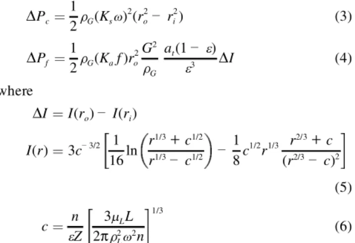
DPc= 1 2»G(Ksv) 2(r2 oê r 2 i) (3) DPf = 1 2»G(Kaf )r 2 o G2 »G at(1 ê e) e3 DI (4) where DI = I(ro) ê I(ri) I(r) = 3cê 3/2 1 16ln r1/3
+
c1/2 r1/3 ê c1/2 ê 1 8c 1/2r1/3 r2/3+
c (r2/3 ê c)2 (5) c = n eZ 3mLL 2p»2 Lv2n 1/3 (6)Ks and Kaf must be estimated from the experimental data. The pressure drop was measured across the gas inlet and outlet; therefore, DPk was not considered. They obtained values of Ks of 0.73 and 0.51 for rotor speeds of 610 and 1150 rpm, respectively. With the rotational Reynolds number, Reu, Kaf can be estimated by the following equation.
log 1
Kaf
= 1.78
+
1.42´ 10ê 5Reu+
1.6 log ReG (7) The deviations between the estimated and experimentalDPvalues were within 6 20%.
Kelleher and Fair10also studied the pressure drop in the
rotating packed bed, and presented the following model.
DP =»Gv2 2 (r 2 oê r 2 i)
+
5B0 22 eMG pZb»G 2 1 r11/10 i ê 1 r11/10 o (8) This equation implied that the pressure drop across the rotating packed bed was made up of two components: a centrifugal force term and a high Reynolds number term. Although equation (8) did not include any empirical parameters, it is not applicable in high liquid-to-gas ratios or the region where the liquid effect appears to be major.Basic and Dudukovic11 presented the very ®rst direct
experimental data for the liquid holdup in the rotating packed bed, using the conductance method. They
established an experimental setup as well as a relationship between bed conductance and liquid holdup. Thus, with the electrical signal from the rotating packed bed, the liquid holdup in the bed may be estimated. They found liquid holdup dependent on the liquid ¯ow rate and rotor speed; the increase of the latter led to less liquid holdup. They also showed that holdup cannot be interpreted by the ®lm ¯ow model based on the assumptions that liquid is the only ¯owing phase, and the packing surface is completely wetted. However, these assumptions are unlikely to be valid in real ¯ow phenomena. Thus, the ®lm ¯ow model derived by them failed to predict liquid holdup consequently.
In conventional packed beds, the relationship between the liquid holdup and the pressure drop was investigated widely in the open literature. However, for the rotating packed bed, very little information has been proposed, as indicated. Consequently, this work is to develop a model to relate the liquid holdup and the pressure drop in a rotating packed bed with both gas and liquid ¯ows. As a result, the pressure drop correlations can be used as described above to predict liquid holdup in the rotating packed bed.
MODEL DEVELOPMENT
Munjal et al.12 presented a model based on the
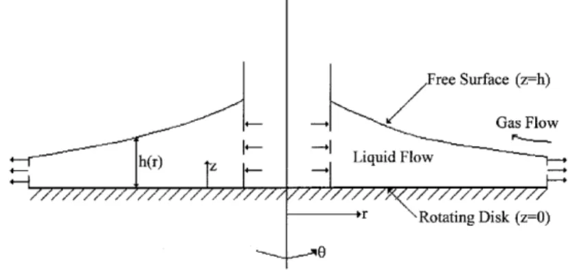
momentum integral method to predict the ®lm thickness and the velocity pro®les in the rotating packed bed. Although it may be applicable for mass-transfer in the rotating packed bed, it only can predict liquid holdup for the case of no gas ¯ow or low gas ¯ow rate. It must be modi®ed by introducing the gas ¯ow effect. The rotating packed bed may be visualized as a stack of rotating disks (as illustrated in Figure 1); hence, the hydrodynamics could be considered over a rotating disk. The velocity pro®le and thickness of the liquid ®lm on a rotating disk have been studied by several investigators (such as Matsumoto et al.14; Thomas et al.15). However, they only analysed liquid ®lm in the absence of the gas.
The condition that gas ¯ows over the free liquid surface on the rotating disk may be considered (as shown in Figure 2). The liquid velocity in the ®lm is assumed to be independent ofu . The equations of continuity and motion for a constant-density liquid may be written as
¶Vr ¶r
+
Vr r+
¶Vz ¶z = 0 (9) Vr ¶Vr ¶r ê V2 u r+
Vz ¶Vr ¶z =nL ¶2V r ¶z2 ê 1 »L ¶P ¶r (10) Vr¶Vu ¶r+
VrVu r+
Vz ¶Vu ¶z =nL ¶2V u ¶z2 (11)where Vr is the velocity in the radial direction, Vz is the velocity in the axial direction which is perpendicular to the disk surface, Vu is the velocity in the tangential direction,
and¶P/¶r is caused by the gas. In equations (10) and (11), the termsnL(¶/¶r){(1/r)(¶/¶r)(rVr)} andnL(¶/¶r){(1/r)(¶/¶r) (rVu)} have been omitted because these terms are an order of
magnitude small than the terms on the right-hand side. The boundary conditions are given by at the disk surface (z = 0)
Vr= 0 (12a)
Vu = rv (12b)
Vz= 0 (12c)
at the free surface (z = h) ¶Vr
¶z = 0 (13a)
¶Vu
¶z = 0 (13b)
To overcome the dif®culty of numerical computation, this problem should be simpli®ed by assuming a velocity pro®le similar to that of the boundary layer over the ¯at plate:
Vr= V ¥ r 3 2 z hê 1 2 z3 h3 (14a) Vu = Vu¥ 3 2 z hê 1 2 z3 h3
+
rv (14b)where Vr¥is the radial velocity at the free surface (i.e. gas-liquid interface) and only depends on r, V¥
u is the tangential
velocity at the free surface, relative to the disk surface, and also only depends on r. The above equations satisfy four out of the ®ve boundary conditions [equations (12a), (12b), (13a) and (13b)]. Also, the axial velocity can be obtained by integating equation (9) and using equation (12c)
Vz = ê …z 0 ¶Vr ¶r
+
Vr r dz (15)It is assumed that the rotating packed bed consists of n layers of hypothetical rotating disks, therefore, the volu-metric liquid ¯ow rate, Q, can be written as
Q = n 2pr …h o Vrdz 0 @ 1 A (16)
where n is the number of the hypothetical rotating disks and is approximately equal to the ratio of the height of the bed and the diameter of the packing, Zb/dp. From the above equation and equation (14a), the estimated thickness of the liquid ®lm in the bed can be obtained:
h =5prV4Qd¥p
rZb
(17) Substituting equations (14a), (14b) and (15) into equations (10) and (11), with equation (17) and integrating the resulting equations with respect to z between z = 0 and
z = h, the following two equations may be obtained for the
velocity at the free liquid surface: dV¥ r dr = V¥2 u Vr¥r
+
175 68 V¥ u v Vr¥+
35 17 rv2 Vr¥ ê 105 34 nL h2+
35 17 1 V¥ r »L ê dP dr (18) dVu¥ dr = ê 175 68 vê V¥ u r ê 105 34 nLV¥ u V¥ rh2 (19) where dP/dr may be evaluated by the following equation based on the research of Keyvani and Gardner7without anyexperimental data of pressure drop. dP dr = »Gv 2 r ê »G Å VG e2 d ÅVG dr
+
A ÅVG+
B ÅV 2 G (20)where ÅVG is the super®cial gas velocity, de®ned as MG/2prZb»G; A and B are the constants of Morton’s model16. A =8.5mGa2t e3 B =at»G e3 Reê 0.1 =at»G e3 MG 2prZbatmG ê 0.1 = B0r0.1
With a further computation, equation (20) can be rewritten as the following equation.
dP dr = »Gv 2r
+
» G MG 2pZb»Ge 2 1 r3+
A ÅVG+
B0r 0.1VÅ2 G (21) If the correlations of the pressure drop are as in equations (1) and (8), dP/dr may be considered as DP/(roê ri). As a result, for any given initial condition (V¥r = Vr,0¥ and Vu¥= Vu¥,0at r = ri), equations (18) and (19) can be solved Figure 2. Schematic of ¯ow over the rotating disk.
to obtain the values of V¥
r and Vu¥ numerically. Then with
equations (14a) and (14b), the velocity pro®le in the bed can be calculated. For known values of V¥
r , equation (17) can be used to calculate the estimated thickness of the liquid ®lm as a function of r.
Matsumoto et al.14 used Navier-Stokes equations in cylindrical coordinates by introducing the dimensionless parameters to obtain the relationships between the radial, the tangential and the axial velocity distributions. These relationships were similar to equations (9), (10) and (11), but were written in the dimensionless form without the effect of pressure drop. They adopted the polynomial approximation of higher degrees for the components of velocity pro®les. The resultant solutions for the velocity components give a fair prediction of the thickness of liquid ®lm in comparison with the experimental data. Their solutions may be applied to the rotating packed bed by introducing equation (16) to obtain the following relationship. Qdp 2pr2pnvZ b =1 2a1h 2 oê 1 6h 3 oê 1 12b1h 4 oê 1 60b1h 5 o (22) where ho is de®ned as h v/n p
and the algebraic equations with respect a1 and b1 are given by
a1ê hoê b1h 2 oê 1 3b1h 3 o = 0 (23) b1
+
a1h 2 o+
1 3(a1b1ê 1) = 0 (24) From equations (22), (23) and (24), the estimated thickness of the liquid ®lm as a function of r can be predicted for the case of the liquid phase.RESULTS AND DISCUSSION
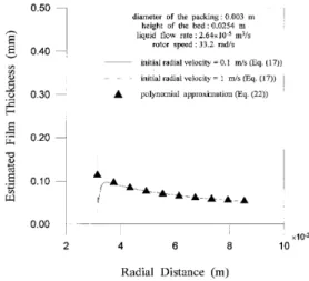
The liquid holdup data of Basic17in a rotating packed bed may be used to verify the model. The investigated rotating packed bed had an axial height of 2.54 cm and the inner, outer radii were 3.14 and 8.54 cm, respectively. The packing was glass beads of dp= 3 mm operated with an air-water ¯uid combination. Figure 3 shows a comparison of the estimated ®lm thickness calculated by equations (17) and (22) ignoring the gas (i.e. dP/dr = 0). It is well known that the three curves start with a different estimated ®lm thickness but quickly merge to a single curve. Although the estimated ®lm thickness calculated by equation (17) depends on the initial radial velocity, as shown in Figure 3, it is seen clearly that the estimated ®lm thickness is not very sensitive to the initial condition except for a very short `transition region’. The estimated ®lm thickness increases from the entrance location, attains a peak and then monotonically decreases along the radial direction. The increase in the estimated ®lm thickness near the entrance is due to the strong frictional resistance which resists the inertial and centrifugal forces in that region, and decreases the radial velocity. The centrifugal force, however, increases with radial distance and overcomes the frictional resistance. As a result, the estimated ®lm thickness decreases monotonically. This trend was also observed by Thomas et al.15who presented experimental data for the ®lm thickness distribution at various ¯owrates and rotational
speeds. However, the polynomial approximation predicts a monotonical decrease in the estimated ®lm thickness along the radial direction. Also, at the distant radial location, the estimated ®lm thickness predicted by both models approaches a similar value because the ¯ow becomes mainly driven by the centrifugal force.
The variations of the estimated ®lm thickness along the radial direction at the lower liquid ¯ow rate without gas are shown in Figure 4 for various rotor speeds. It is shown that the estimated ®lm thickness increases near the entrance, attains a peak and then decreases further away from the inlet. The location of the peak decreases with the increase in the rotor speed. This can be explained by the fact that the lower rotor speed requires the longer distance to resist the frictional force from the surface. However, with higher liquid ¯ow rate, the effect of the inertial force is more dominant than that of the centrifugal force. As a result, at lower rotor speeds, the estimated ®lm thickness decreases near the entrance and then increases later along the radial distance, as shown in Figure 5. Also, when the centrifugal force is dominant (i.e. the higher rotor speed), the estimated ®lm thickness decreases further downstream. Based on the
Figure 3. Comparison of the estimated ®lm thickness predicted by two methods in the rotating packed bed in the absence of the gas (V¥
u,0= 5 m sê 1).
Figure 4. Comparison of the estimated ®lm thickness distributions for various rotor speeds at lower liquid ¯ow rate in the absence of the gas (V¥
above analysis, it is well realized that the forces affecting the estimated ®lm thickness are the inertial force, the frictional force, and the centrifugal force. Also, it is found that the pattern of the ®lm for various conditions is quite complex due to the relative magnitude of three forces that may affect the hydrodynamics over the rotating disk.
The polynomial approximation method cannot predict the estimated ®lm thickness affected by the gas, as shown in Figure 6. At a short radial distance, the polynomial approximation method underpredicts the estimated ®lm thickness due to the effect of gas. Because the frictional resistance from the surface has to overcome the inertial and centrifugal force, and also the gas ¯ow, the peak is higher than the case without gas. While further away from the entrance, the ¯ow is mainly determined by the centrifugal force, so the estimated ®lm thickness by the polynomial approximation approaches that of the above model (equa-tion (17)) as that in the absence of the gas. Therefore, the above model (equation (17)) should have better applic-ability even though the polynomial approximation can also
provide a good prediction for the estimated ®lm thickness in the absence of the gas.
The mean estimated thickness of the liquid ®lm, Åh, can be de®ned as Åh = 1 roê ri … ro ri hdr (25)
The real ¯ow behaviour can be visualized by including the fact that the surface area of the packing is not completely wetted for various conditions encountered in practice. As a result, the following relationship exists between the liquid holdup, hL, and the wetted surface area, aw:
hL= Åh´ aw (26)
To predict liquid holdup, the dependence of Åh and awon the various operating conditions must be known. Based on the above description, Åh can be found for any conditions from equations (17) and (25). However, in the rotating packed bed, there is no information for the wetted surface area in the literature. Consequently, a correlation must be devel-oped for the wetted surface area while liquid is the only ¯owing phase (i.e. dP/dr = 0). With the experimental data for liquid holdup from Basic17 and the mean liquid
estimated ®lm thickness obtained by equations (17) and (25), the values of the wetted surface area can be obtained for various conditions by using equation (26), then the following correlation is derived.
aw at = 584ReêL1.03We0.576 L Fr 0.123 L (27)
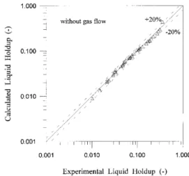
Figure 7 shows that the predicted liquid holdup using equations (17), (26) and (27) is very close to the experimental liquid holdup when the liquid is the only ¯owing phase. When the general case of the two-phase ¯ow of both gas and liquid is considered, the liquid holdup will be in a different form from that in the one-phase ¯ow. As a result, equations (17) and (25) are used to predict the mean estimated liquid ®lm thickness, considering the effect of the pressure drop (i.e. the effect of the gas), and then equation (27) is used to obtain the liquid holdup for the two-phase ¯ow by assuming a similar wetted area for both one-phase and two-phase ¯ows. As shown in Figure 8, the results
Figure 5. Comparison of the estimated ®lm thickness distributions for various rotor speeds at higher liquid ¯ow rate in the absence of the gas (V¥
r,0= 0.1 m sê 1, Vu¥,0= 5 m sê 1).
Figure 6. Comparison of the estimated ®lm thickness predicted by two methods in the rotating packed bed in the presence of the gas (V¥
r,0= 0.1 m sê 1, Vu¥,0= 5 m sê 1).
Figure 7. Comparison of experimental and predicted liquid holdup in the absence of gas (model: equations (17), (26) and (27); data from Basic17).
predicted by equations (17), (26) and (27) lie within6 20% of the experimental data. Thus, this new model is acceptable to predict the liquid holdup with the experimental data of the pressure drop.
APPLICATIONS
If the pressure drop in a rotating packed bed is known, the liquid holdup can be calculated using the above method (i.e. equations (17), (26) and (27)). Liu et al.18has investigated a rotating packed bed of axial height 2.5 cm and inner, outer radius of 4.5 and 7 cm, respectively. They presented some results of the pressure drop for an air-water system. With those data, the liquid holdup can be estimated for various operating conditions. As shown in Figure 9, it is realized that the liquid holdup is affected by the gas velocity and increases with the gas rate. This result agrees with the ®ndings of some authors who studied the hydrodynamics in the conventional packed bed. It is also seen that the liquid holdup and the pressure drop have a similar tendency.
For the conventional packed bed of the low interaction regime where the ¯ow of one phase is littlely affected by the other phase, Specchia and Baldi19 thought that the
hydrodynamics of the liquid on the packing is very different
from that of the free liquid. Hence, a general correlation for the liquid holdup in co-current two-phase ¯ow can be obtained by introducing the modi®ed Galileo number (Ga*): hL= 3.86 Re 0.545 Ld Gaê 0.42 atdp e 0.65 e (28)
where Ga is de®ned by:
Ga = d3 p»L »Lg
+
DP Z m2 L (29)Ga may be modi®ed in equation (28) to predict the liquid
holdup in the rotating packed bed as the following equation, since the ¯ow direction of gas and liquid is inverse.
Ga = d3 p»L »Lacê DP roê ri m2 L (30) It is noted clearly that this correlation takes into account the in¯uence of the pressure drop on the liquid holdup. This can be demonstrated by the comparison of this correlation (equation (28)) with the predictions by the model (equations (17), (26) and (27)) for two-phase ¯ow. This comparison is shown in Figure 10 for two-phase ¯ow with the pressure drop data from Liu et al.18. When the constant (3.86) in equation (28) is replaced with 1.2, the discrepancy between this correlation and the prediction is within6 20%, as shown in Figure 10. This implies that the liquid holdup in the rotating packed bed is less than that in the conventional packed. Consequently, this often used correlation seems to be able to predict the liquid holdup in the rotating packed bed with two-phase ¯ow.
CONCLUSIONS
Because the liquid holdup is very dif®cult to measure in the rotating packed bed, it would be useful to ®nd another method to obtain the liquid holdup. Based on the analysis of the above, a model has been developed to predict the liquid holdup using the pressure drop data which is easier to measure. It is also evident that the liquid holdup is in¯uenced slightly by the gas. Moreover, the correlation
Figure 8. Comparison of experimental and predicted liquid holdup in the presence of gas (model: equations (17), (26) and (27); data from Basic17).
Figure 9. Effect of gas ¯ow rate on liquid holdup (liquid holdup calculated by equations (17), (26) and (27); pressure drop data from Liu et al.18).
Figure 10. Comparison of liquid holdup estimated by equation (28) and equations (17), (26) and (27) (pressure drop data from Liu et al.18).
(equation (28)) for the liquid holdup in the conventional packed bed can be extended to estimate the liquid holdup in the rotating packed bed.
NOMENCLATURE A, B, constants in equation (20)
B0 constants in equation (8)
a1, b1 de®ned by equations (23) and (24)
ac centrifugal acceleration, m sê 2, =v2(ri+ro)/2
at total speci®c surface area of the packing, m2mê3
aw wetted surface area of the packing, m2mê3
c de®ned by equation (6)
dp spherical equivalent diameter of the packing, m, = 6(1 ê e)/at
G gas ¯ow rate, kg mê 2sê1
g gravitational acceleration, m sê2
h estimated liquid ®lm thickness, m Åh mean estimated liquid ®lm thickness, m hL liquid holdup (ê )
I(r) de®ned by equation (5) Ks slip factor (ê )
Kaf de®ned by equation (7)
MG mass ¯ow rate of gas, kg sê 1
L liquid ¯ow rate, kg sê1
n number of rotating disks P pressure of gas, Pa DP pressure drop, Pa
DPc pressure drop due to centrifugal force, Pa
DPf pressure drop due to frictional force, Pa
DPk pressure difference due to change in gas velocity, Pa
Q volumetric ¯ow rate of liquid, m3sê 1
Rh hydraulic radius, m
r coordinate direction parallel to disk surface ri inner radius of the packed bed, m
ro outer radius of the packed bed, m
uL super®cial liquid velocity, m sê 1
VGavg average super®cial gas velocity, m sê 1
Å
VG super®cial gas velocity, m sê 1
Vr liquid velocity in the radial direction, m sê1
V¥
r radial velocity at the gas-liquid surface, m sê 1
V¥
r,0 Vr¥at r = rim sê1
Vz liquid velocity in the axial direction, m sê 1
Vu liquid velocity in the tangential direction, m sê 1
V¥u tangential velocity at the gas-liquid surface relative to the disk surface, m sê 1
V¥u,0 Vu¥at r = ri, m sê 1
z coordinate direction perpendicular to disk surface Zb axial height of the packing, m
Z height of the conventional packed bed, m Greek letters e voidage (ê ) mG gas viscosity, kg mê1sê1 mL liquid viscosity, kg mê 1sê 1 »G gas density, kg mê3 »L liquid density, kg mê 3
nG dynamic gas viscosity, m2sê1
nL dynamic liquid viscosity, m2sê1
s surface tension of liquid, N mê 1
v angular velocity, rad sê1
Dimensionless groups FrL Froude number (u2Lat/ac)
Gr Grashof number for liquid de®ned by equation (29) or equation (30) ReG gas Reynolds number (4RhG/mG)
ReL liquid Reynolds number (uL/atnL)
ReLd liquid Reynolds number (uLdp/nL)
Reu rotational Reynolds number (Ksvro2/nG)
WeL Weber number (u2L»L/ats)
REFERENCES
1. Ramshaw, C. and Mallinson, R. H., 1981, Mass transfer process, US Patent 4,283,255.
2. Ramshaw, C., 1983, HIGEE distillationÐAn example of process intensi®cation, Chem Eng, 13±14 Feb.
3. Short, H., 1983, New mass-transfer ®nd is a matter of gravity, Chem Eng, 23±29 Feb.
4. Basta, N., 1987, Facelift for distillation, Chem Eng, 14±16 Mar. 5. Bucklin, R. W. and Won, K. W., 1987, Higee contactors for selective
H2S removal and superdehydration, Laurance Reid Gas Conditioning
Conf, University of Oklahoma, March 2±4.
6. Fowler, R., Gendes, K. F. and Nyguard, H. F., 1989, Commercial scale demonstration of Higee for CO2/H2O removal, 21st Annual Offshore
Technology Conf, Houston, TX, May.
7. Keyvani, M. and Gardner, N. C., 1989, Operating characteristics of rotating beds,Chem Eng Prog, 85: 48±52.
8. Singh, S. P., Wilson, J. H., Counce, R. M., Villiers-Fisher, J. F., Jennings, H. L., Lucero, A. J., Reed, G. D., Ashworth, R. A. and Elliott, M. G., 1992, Removal of volatile organic compounds from ground-water using a rotary air stripper,Ind Eng Chem Res, 31: 574±580.
9. Kumar, M. P. and Rao, D. P., 1990, Studies on a high-gravity gas-liquid contactor,Ind Eng Chem Res, 29: 917±920.
10. Kelleher, T. and Fair, J. R., 1996, Distillation studies in a high-gravity contactor,Ind Eng Chem Res, 35: 4646±4655.
11. Basic, A. and Dudukovic, M. P., 1995, Liquid holdup in rotating packed beds: Examination of the ®lm ¯ow assumption,AIChE J, 41:
301±316.
12. Munjal, S., Dudukovic, M. P. and Ramachandran, P. A., 1989, Mass transfer in rotating packed beds: I. Development of gas-liquid and liquid-solid mass-transfer coef®cients,Chem Eng Sci, 44: 2245±2256.
13. Burns, J. R. and Ramshaw, C., 1996, Process intensi®cation: Visual study of liquid maldistribution in rotating packed beds,Chem Eng Sci,
51: 1347±1352.
14. Matsumoto, S., Saito, K. and Takashima, Y., 1973, The thickness of a viscous liquid ®lm on a rotating risk, J Chem Eng Japan, 6: 503±507. 15. Thomas, S., Faghri, A. and Hankey, W., 1991, Experimental analysis and ¯ow visualization of thin liquid ®lm on a stationary and rotating disk,ASME J Fluids Eng, 113: 73±80.
16. Morton, F., King, P. J. and Atkinson, B., 1964, Operating character-istics of packed columns Part I: Below the ``load’’ point, Trans IChemE, 42: T35±T43.
17. Basic, A., 1992, Liquid holdup and hydrodynamics of rotating packed beds, PhD Diss (Department of Chemical Engineering, Washington University, St. Louis, MO).
18. Liu, H. S., Lin, C. H., Wu, S. C. and Hsu H. W., 1996, Characteristics of a rotating packed bed,Ind Eng Chem Res, 35: 3590±3596.
19. Specchia, V. and Baldi, G., 1977, Pressure drop and liquid holdup for two phase concurrent ¯ow in packed beds,Chem Eng Sci, 32: 515±
523.
ACKNOWLEDGEMENT
The ®nancial support from the National Science Council is gratefully acknowledged.
ADDRESS
Correspondence concerning this paper should be addressed to Professor Hwai-Shen Liu, Department of Chemical Engineering, National Taiwan University, Taipei, Taiwan, ROC, (E-mail: [email protected]).
The manuscript was received 13 April 1999 and accepted for publication after revision 10 November 1999.