THPM
14.7
Architecture Design
of
MPEG-2
Decoder System
Yung-Pin Lee, Liang-Gee Chen, and Chung-Wei Ku
National Taiwan University, Taipei, Taiwan,
R. 0. C.
Abstract
An architecture for the VLSI Design of MPEG-2 video
decoder is introduced t o achieve the MPQML (Main
Profile, Main Level)[l]. Hardware complexity is ana- lyzed, and decoding unit (VLD, IQ, IDCT, MC, etc.) is designed t o reach the required performance.
1
Introduction
With t h e advance of image compression, various com- pression standards, such as H.261, J P E G , MPEG-1, are
developed. MPEG-1[2] was optimized for a bitrate of
about 1.5 Mbits/s and for a S I F ( 3 5 2 ~ 2 4 0 ~ 3 0 ) format. However, for the request of higher bitrate and resolu- tion, the Moving Pictures Expert Group (MPEG) com- pleted the committee draft of MPEG-2[1] in Nov. 1993.
MPEG-2 serves a wide range of applications, bitrate,
resolutions, qualities, and services. Applications cov- er digital storage media, television broadcasting, and communication. In order t o serve various applications,
a limited number of subsets of the MPEG-2 syntax are
stipulated by means of “profile” and “level” (see Ta-
ble l). This paper mainly describes the MP@ML for
its simplicity and completeness.
2
Architecture
of
MPEG-2
A MPEG-2 decoder system can be partitioned into four
modules: host interface, memory interface, decoding unit, and display interface, which are all. interconnected
by a local bus (see Fig. 1)[3]. The maximum required
memory bandwidth for local DRAM access is
720x 576x30x( -x 1.5~2+1.5+1.5) = 84.56 Mbytes/s,
that is 11.8 ns. With 48-b d a t a bus, the access time
needs 71 ns which is hard t o achieve by random ac-
cess of DRAM. So page mode for memory access is
needed. Memory size needs a t least 10.2 Mbits which includes two pictures storage and output buffer. T h e
81 64
VBV Buffer size for MP@ML is 1.8 Mbits, So 16 Mbits
for total DRAM size will be enough.
3
Design of Decoder Unit
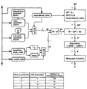
Decoding unit[4] includes VLD (variable length decod- ing), inverse scan, I Q (inverse quantization), IDCT, and MC (motion compensation). T h e area of MC and
IDCT is more larger than other modules, so reduce
the size of these two modules will have apparent ef- fect on reducing the whole system size. Traditional- ly, Design of 2-D IDCT is splited into two 1-D ID- CT’s. With the consideration of hardware area and latency, we used direct 2-D I D C T method rather than row-column method. We proposed a more regular str- cuture for direct 2-D IDCT. T h e input d a t a reorder can be solved by arranging the output of inverse scan. Fig. 2 shows the architecture for IQ which has more reg- ular scheme. MC is composed of motion vector decoder and predicted picture reconstructor. Motion vector de-
coder (Fig.
4)
generates the motion vector and updatespredicted motion vector. Predicted picture reconstruc- tor (Fig. 3) reads previous reconstructed pixels t o for-
m current pixels with half-pel accuracy. T h e time for
reading previous picture pixels from local bus and writ- ing current constructed pixels t o local bus is arranged carefully so as not t o increase the latency.
4
Summary
After completing the design of MPQML, there are two ways t o continue this work:
HDTV: Speed up the architecture t o achieve the HDTV level (MPQHL). Future HDTV system will
be similar t o our proposed architecture except it’s
faster. So experience of design on MPQML can be
directly applied on HDTV design.
Scalability: Scalability enable a decoder t o recon-
struct useful video from pieces of a total bitstream.
Table 1: Profiles and levels for MPEG-2.
Ofile Simple Main SNR High
Scalable Scalable High
High 1440
Main
L O W
So
it
makes MPEG-2 suitable for d a t a transmis-sion a n d multimedia applications. However, the architectures of both based layer and enhencement
layer are similar t o MPQML, so it’s easy t o expand
our architecture t o scalable architecture.
MPCBL HP@IIL
MPCH1440 SSPCH144C HPBH1440 SPCML MP@ML SNPCML NP@ML
MPCLL SNP@LL
References
[l]
ISO/IEC
13818-2, “Information Technology-
generic coding of moving pictures and associated
audio,” Committee Draft, Nov. 1993.
[2] M P E G , “IS0 CD11172-2: Coding of moving pic-
tures a n d associated audio for digital storage me- dia a t u p t o about 1.5Mbits/s”, Nov.1991.
[3] T. Fautier, “VLSI implementation of M P E G de-
coders,” IEEE ISCAS’94 tutorials, pp. 164-172, May 1994.
[4] T. Onoye, Y. Morimoto, T. Masaki, and I. Shi-
rakawa, “Design of inverse D C T and motion com-
pensator for MPEG-2 HDTV decoding,” APC-
CAS’94, pp. 608-613, Dec. 1994.
Figure 1: Architecture of MPEG-2 decoder system.
Figure 2: Architecture of inverse quantization.
I delta L ver
4
range9-
vector’ - motion-code - zero - motlon-residue - t-code - signFigure 3: Architecture of motion vector decoder.
-1- minoblockpollon-forward h v AS block I SBI
Figure 4: Architecture of Predicted picture reconstruc-
tor.