國
立
交
通
大
學
資訊科學與工程研究所
碩 士 論 文
應用於車載隨意網路環境下
以移動式閘道器為基礎之路由協定
A Mobile-Gateway Routing Protocol
for Vehicular Networks
研 究 生:潘欣雅
指導教授:簡榮宏
博士
應用於車載隨意網路環境下
以移動式閘道器為基礎之路由協定
A Mobile-Gateway Routing Protocol
for Vehicular Networks
研
究 生:潘欣雅
Student:Hsin-Ya Pan
指導教授:簡榮宏
Advisor:Rong-Hong Jan
國
立 交 通 大 學
資
訊 科 學 與 工 程 研 究 所
碩
士 論 文
A ThesisSubmitted to Institute of Computer Science and Engineering College of Computer Science
National Chiao Tung University in partial Fulfillment of the Requirements
for the Degree of Master
in
Computer Science July 2011
Hsinchu, Taiwan, Republic of China
i
應用於車載隨意網路環境下以移動式閘道器為基礎之
路由協定
研究生:潘欣雅 指導教授:簡榮宏 博士
國立交通大學資訊科學與工程研究所
摘
要
近幾年來車載隨意網路(Vehicular Ad Hoc NETwork, VANET)的相關研究越 來越受重視,已成為炙手可熱的研究議題。在設計車間(vehicle-to-vehicle, V2V) 通訊的路由協定上,必須考量到有時因車輛移動的速度變化太快,而造成通訊中 斷的狀況。然而利用車輛對基礎建設網路(vehicle-to-infrastructure, V2I)的溝通可 以 大 幅 改 善 以 上 的 問 題 。 在 此 篇 論 文 中 , 我 們 提 出 一 個 路 由 協 定 名 為 MGRP(Mobile-Gateway Routing Protocol)協定,MGRP 協定結合了 V2V 和 V2I 兩者的通訊方式,在系統中,所有的車輛都具備有 802.11 的通訊介面,此外, 部分的車輛另具備 3G 的介面,這些車輛稱為移動式閘道器。而移動式閘道器可 透過 IEEE 802.11 介面接收一般車輛的封包,再利用 3G 介面將封包經由基地台 送至閘道器控制中心。而閘道器控制中心會依據目的地車輛的位置,尋找目的地 周邊的移動式閘道器,並將封包轉送給這些移動式閘道器,透過移動式閘道器以 廣播的方式將封包送至目的地車輛。實驗結果顯示,我們提出的 MGRP 比起傳 統的 GPSR(Greedy Perimeter Stateless Routing for Wireless Networks)協定明顯提 升封包傳送率以及縮短整體路徑。
ii
A Mobile-Gateway Routing Protocol
for Vehicular Networks
Student:Hsin-Ya Pan Advisor:Dr. Rong-Hong Jan
I
NSTITUTE OF
C
OMPUTER
S
CIENCE AND
E
NGINEERING
N
ATIONAL
C
HIAO
T
UNG
U
NIVERSITY
Abstract
Development of vehicular ad hoc networks (VANETs) has drawn intensive attention in recent years. Designing routing protocols for vehicle-to-vehicle (V2V) communication in VANET may suffer from frequent link change and disconnection. Vehicle-to-infrastructure (V2I) communication can overcome the challenge by relaying packets through the backbone network, but is limited to those areas where a RSU exists. In this thesis, we present a position-based routing protocol, named mobile-gateway routing protocol (MGRP), for VANETs. The MGRP combines V2V and V2I communications, and utilizes a part of vehicles as mobile gateways. Each mobile gateway connects with a base station through a 3G interface and communicates with other vehicles without the 3G interface through an IEEE 802.11 interface. Upon received packets from a vehicle, the mobile gateway forwards the packets to a gateway controller via the base station. The gateway controller then searches the position of the destination vehicle and determines a set of gateway vehicles close by the destination to forward the packets. Simulation results show that the MGRP can significantly improve the packet delivery ratios and reduce the transmission hop count.
iii
致謝
在此我要感謝這兩年中指導我進行研究的簡榮宏教授,感謝老師不厭其煩的 教導我學術研究的進行方向以及研究方法的探討。藉由不斷的修正與改進研究的 方法以及分析其效能,終於能提出此篇完整的方法。 除了指導教授之外,實驗室的我夥伴也是我研究生活中重要的推手。感謝實 驗室學長姐(安凱、嘉泰、蕙如、鈺翔、家瑋、淑盈、志賢、子興、嘉瑋、宇田) 、 同學(冠傑、良叡) 以及學弟妹(唯義、曰慈、慈麟、紹閔、怡萱)的共同努力, 以及生活上的協助與陪伴。學業上的共同作業以及許多的情感交流讓我的研究生 涯留下許多深刻的印象。 最後我要感謝我的家人以及眾多在這段時間中支持我走過研究生活的朋友 們,感謝你們一路上的支持與鼓勵,讓我可以堅持到最後並完成人生重要的里程 碑。在此,本文獻要獻給一路關懷勉勵我的家人以及朋友們。iv
Contents
Chapter 1 Introduction ··· 1
Chapter 2 Related Work ··· 4
Chapter 3 Mobile Gateway Routing Protocol ··· 6
3.1 The Architecture of Mobile Gateway Routing ··· 6
3.2 Assumption ··· 7
3.3 MGRP Routing Protocol ··· 8
Chapter 4 Simulation and Performance Evaluation ··· 17
4.1 Simulation Environment ··· 17
4.2 Simulation Results ··· 19
Chapter 5 Conclusions ··· 26
v
List of Figures
Figure 1. Architecture of mobile gateway routing ··· 7
Figure 2. Scenario of the source vehicle sending packets to a destination vehicle ··· 8
Figure 3. Packet forwarding in different scenarios··· 10
Figure 4. The priority of the route to destination vehicle is higher than gateway vehicle ··· 12
Figure 5. The flow chart of the source vehicle sending a packet to the gateway vehicle ··· 13
Figure 6. Gateway controller forwards packets to a set of gateway vehicles which are less than 500m to the destination ··· 14
Figure 7. The flow chart of the back-end server forwarding a packet to the gateway vehicle ··· 15
Figure 8. Simulation street layout ··· 18
Figure 9. The percentage of gateway vehicles vs. packet delivery ratio ··· 19
Figure 10. Packet delivery ratio vs. maximum node speed ··· 20
Figure 11. Average hop count vs. maximum node speed ··· 21
Figure 12. Routing overhead vs. maximum node speed ··· 22
Figure 13. Packet delivery ratio and overhead vs. hop count··· 22
Figure 14. Packet delivery ratio vs. maximum node speed with fixed RSU and mobile gateway vehicle ··· 23
vi
Figure 15. Routing overhead vs. maximum node speed with fixed RSU and mobile gateway vehicle ··· 24 Figure 16. Average hop count vs. maximum node speed with fixed RSU and mobile gateway vehicle ··· 24
vii
List of Tables
1
Chapter 1
Introduction
Vehicular Ad Hoc Networks (VANETs) have received increasing attention from the research and industrial communities recently. Many valuable applications, such as entertainments, trip planning, and accident avoidance, have been envisioned in VANETs.
Vehicle-to-Vehicle (V2V) and Vehicle-to-Infrastructure (V2I) are two major types of communications in VANET. Each vehicle equipped with an On-Board Unit (OBU) can either transmit hop-by-hop to the destination using V2V communication or transmit to a Roadside Unit (RSU) using V2I communication.
Different from traditional wireless networks, designing a routing protocol for V2V communication is more challenging. The network topology may change rapidly due to the high speed characteristic of vehicles. Thus, a proactive routing, such as DSDV [1] that pre-establishes shortest paths between nodes, is not appropriate. In other words, a packet could be transmitted in a longer hop in V2V communication. Moreover, the disconnection problem may happen at the areas of low traffic density, further degrading the packet delivery ratio.
2
Although VANETs would not encounter some problems such as power saving or the limitation of computing capability, but the disconnection problems still are the serious issues and that may cause the frequently discovery route to result in broadcast storm problems. Therefore, to overcome the above problems is essential to design the suitable routing protocol.
The challenges in V2V can be overcome by the support of V2I communication. A vehicle can firstly transmit packets to a RSU. The RSU connects to the backbone network and thus can forward packets for vehicles using a more efficient and reliable way. However, due to the limited transmission ranges of OBUs, the support of V2I communication is only restricted to those areas where a RSU is reachable. In other places, the above challenges still exist.
In this thesis, we propose a position-based routing protocol, namedmobile-gateway routing protocol (MGRP) for VANETs. The MGRP combines V2V and V2I
communication, and utilizes a part of vehicles as mobile gateways to extend the coverage of fixed RSUs. The OBU on each mobile gateway is equipped with an IEEE 802.11 interface and a 3G interface. The other vehicles without the 3G interface can forward packets through 802.11 links to the nearest mobile gateway. Upon received a packet, the mobile gateway forwards the packet to a gateway controller through the 3G interface. The gateway controller then searches the position of the destination vehicle and determines a set of gateway vehicles close by the destination to forward the packet.
Simulation results show that the MGRP can significantly improve the packet delivery ratios and reduce the transmission hop counts. In other words, the proposed protocol can provide vehicles with more instantaneously services. We also investigated the percentage of gateway vehicles to find the appropriate ratio to
3
guarantee the successful delivery ratio.
The rest of the thesis is organized as follows. In Chapter 2, we review the previous studies and related works. Then, the system model, assumptions and detailed description of MGRP are presented in Chapter 3. In Chapter 4, we evaluate the proposed approach by simulation and compare with the GPSR routing protocol. Finally, a conclusion is given in Chapter 5.
4
Chapter 2
Related Work
Researches on V2I communication can be divided into two categories: One is that the RSU just plays the role of packet storage but not provides the function of transmission, such as SADV [2]. The other focuses on utilizing the pre-established RSU for transmission. When a vehicle enters the transmission range of a RSU, it will start to send or receive the data packet with the RSU.
A number of routing protocols that use fixed infrastructures to improve the packet delivery have been proposed. In MPARP [3], each vehicle is equipped with an IEEE 802.11 and an IEEE 802.16 interfaces. When routes exist, vehicles can communicate directly with each other using the IEEE 802.11 mode; otherwise, their communication will be taken over by a base station using the IEEE 802.16 mode. In RAR [4] and DDR [5], each section of the road is embraced by two RSUs. When a vehicle has some packets for another vehicle on a different section, it transmits to one of the RSU on which it is located. Then, the packets will be forwarded to the destination through the backbone network. Similarly, the routing protocol in [6] tries to make a proper decision on whether to broadcast or to use end-to-end transmission based on the information provided by RSUs.
5
Although vehicular communication can be assisted by the support of V2I model, the advantage is restricted to those areas where fixed infrastructures exist. To overcome it, the MIBR protocol in [7] introduces the concept of mobile gateways. It employs each bus as a mobile gateway to forward packets for vehicles. Because buses have fixed travel routes and can be equipped with radios of larger transmission ranges (over 300m), it is beneficial to improve the delivery radio and throughput. However, the connectivity between buses is still limited to the period of bus schedules and the covered region of bus routes.
To conquer the above limitations, this paper utilizes a part of vehicles, e.g. taxi, in which 3G infrastructures are added to their OBUs as mobile gateways. Other vehicles without the 3G infrastructures can deliver packets to destinations through those gateway vehicles. Because the coverage of 3G infrastructure is large enough to cover the whole area, the proposed protocol can significantly reduce the hop count and improve the packet delivery ratio.
6
Chapter 3
Mobile Gateway Routing Protocol
In this chapter, we first introduce the architecture and assumptionsof the mobile gateway routing. Then, the MGRP routing protocol is presented in details.
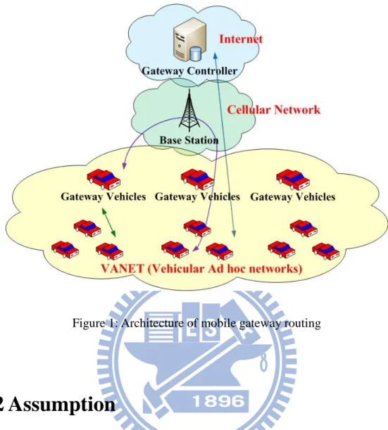
3.1
The Architecture of Mobile Gateway Routing
As shown in Fig. 1, we utilize a part of vehicles as mobile gateways to substitute traditional RSUs. The OBU on each gateway vehicle is equipped with an IEEE 802.11 interface and a 3G interface. The 3G interface is used to communicate with a base station in a cellular network and the 802.11 interface is used to communicate with other vehicles without the 3G interface. When the base station received data packets from a gateway vehicle, it will deliver the packets to a gateway controller. The gateway controller then searches the position of the destination, determines a set of gateway vehicles close by the destination, and sends packets to each of the chosen gateway vehicles via the based station. Finally, those gateway vehicles will transmit the data packets to the destination with IEEE 802.11 links.
7
Figure 1: Architecture of mobile gateway routing
3.2
Assumption
We assume that each vehicle can obtain its position, velocity, and direction through a global positioning system (GPS) equipped on the vehicle. This information will be periodically broadcasted to nearby vehicles within the transmission range using a hello message. We also assume that a digital map with traffic load condition of roads is installed in each vehicle. Besides, if a vehicle found that the route has broken, it will buffer any received data packet and send a RRER packet to the source vehicle for selecting an alternative route. Different from ordinary routing protocols, such as AODV [8], the MGRP limits the time-to life (TTL) value to three hops.
8
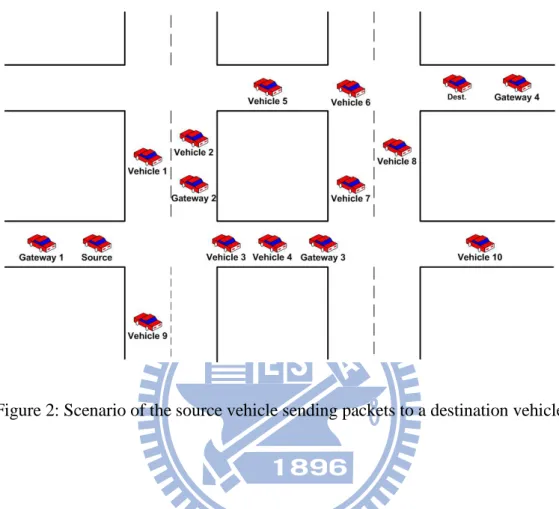
3.3 MGRP Routing Protocol
Figure 2: Scenario of the source vehicle sending packets to a destination vehicle
In MGRP, each vehicle can deliver data packets via a mobile gateway to decrease the transmission hop count and to achieve more reliable communication quality. Fig. 2 shows how a source vehicle (left hand side) sends the packet to a destination vehicle (right hand side). When the source vehicle has some packets for the destination vehicle, it first searches a mobile gateway closest to itself, i.e. Gateway1, and sends packets to the gateway vehicle. Then, Gateway1 forwards the data packets to a base station using the 3G interface. Upon received the packets, the base station delivers the packets to the back-end gateway controller in order to search the position of the destination vehicle and transmits the packets to a set of gateway vehicles close by the destination vehicle, i.e. Gateway4. Finally, Gateway 4 will forward the packets to the destination vehicle via the 802.11 interface. Without the assist from Gateway1, Gateway4, and the
9
gateway controller, the source vehicle has to carry the packets for a while until it meets vehicle1, vehicle3, or vehicle9. The same problem happens on the next vehicle carrying those packets. The above relaying process may cause a longer delay time before reaching the destination vehicle. Even worse, if the packet is forwarded to vehicle9 and there is no further vehicle connecting vehicle9 to the destination, the packet will lose, causing an unreliable transmission.
Now we descript a detail processes. Similar to the AODV protocol, when a vehicle needs to send packets, it first broadcasts a RREQ packet to the neighboring vehicles. Once a neighbor received the RREQ packet, if it has no routing path to the destination, it will rebroadcast the route request to other neighbors. Different from the AODV, the TTL of RREQ is limited to three hops in the MGRP. Once a vehicle receives the RREQ, it first checks whether the hop count is still less than three. If so, the vehicle will become the next forwarder to rebroadcast the RREQ packet; otherwise, the vehicle will drop the RREQ packets. If the information of the destination vehicle was in its routing table or the gateway vehicle receives the RREQ packet, it will send back a RREP packet to the source vehicle. Furthermore, if the vehicle waits for a while and does not receive the RREP packet, it will rebroadcast the RREQ packet and repeat above steps.
After a source vehicle broadcasts the RREQ packet to require a routing path, there are three situations may happened.
The first is that there is no other vehicle beside the source vehicle or cannot find a neighboring vehicle instantly. In this case, the vehicle carries the packets until a vehicle appears within its transmission range. Then, it will forward the packets to the vehicle.
10
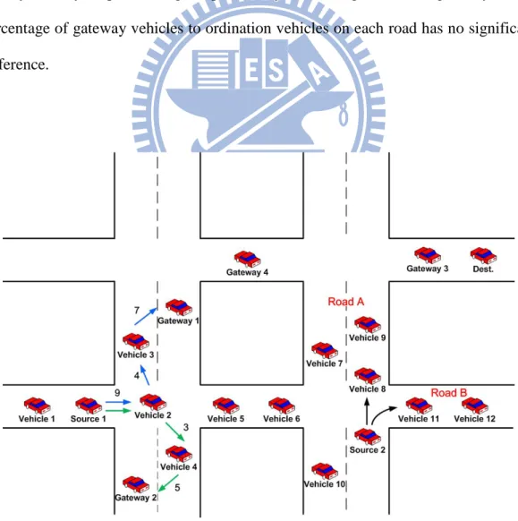
The second situation is th at there are more than one neighboring vehicles, but none of them having a path to a mobile gateway or destination vehicle in three hops. In this case, the source vehicle determines a forwarding direction for the packets according to the road density information. When the vehicle located at an intersection, it will select the direction which has the highest road density. As shown in Fig. 3, there is no routing path that can forward data packet from source 2 to a gateway vehicle or destination vehicle, and the density of road A (3 vehicles) is higher than that of road B (2 vehicles). So, source 2 forwards the packets to vehicle 8 which is on road A. This method can improve the packet delivery ratio, because a higher road density usually implies a higher probability of finding a mobile gateway if the percentage of gateway vehicles to ordination vehicles on each road has no significant difference.
11
The third situation is that there are more than one routing paths that can forward to destinations or gateway vehicles. In this case, the source vehicle needs to select a suitable route path. The MGRP will select the most reliable path to forward the data packets. The reliability of routing path is evaluated by the lifetime of the route. We utilize the following link lifetime formula proposed in [3] to predict the inter-vehicle lifetime, j i ij V V D R lifetime Link − − = _ ,
(1)
where R is the transmission range of each vehicle, Dij is the distance between vehicle i
and vehicle j, Vi : the velocity of vehicle i, and Vj is the velocity of vehicle j. The
lifetime of a routing path is the smallest link lifetime on this path.
As shown in Fig. 3, there are two routes can forward data packets from source 1 to a gateway vehicle. The first path is through Source1 → Vehicle2 → Vehicle3 → Gateway1, and the second path is Source 1 → Vehicle 2 → Vehicle 4 → Gateway2. The lifetimes of each link on the first route path are 9, 4 and 7 seconds, and lifetimes of each link on the second route are 9, 3 and 5 seconds. So the route lifetime of the first path is 4 and the second path is 5, and Source 1 will select the second route path to forward data packets.
Note that if the routing table has recorded the routing path to the destination vehicle, it has the higher priority to select this routing path for transmission.
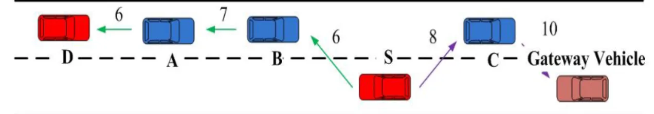
As shown in Fig. 4, there are two routes from source vehicle to destination, S → C → Gateway vehicle (→ Infrastructure → Gateway vehicle → D) and S → B → A → D. At this time, the MGRP protocol will select the route without infrastructure
12
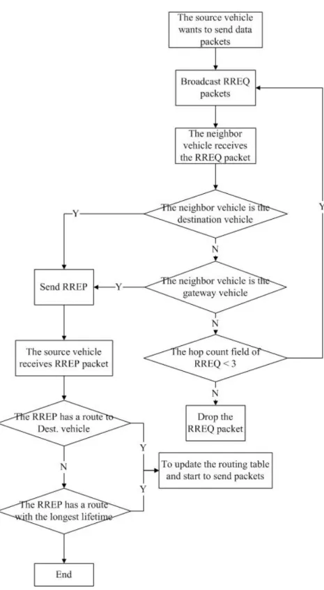
added to forward data packets to destination, although the lifetime of this path is lower than the lifetime of the path to gateway vehicle. The procedure of the source vehicle sending a packet to the gateway vehicle is summarized in Fig. 5.
Figure 4: The priority of the route to destination vehicle is higher than gateway vehicle
As shown in Fig. 5, when the source vehicle wants to send the data packets, it starts to broadcast RREQ messages. The neighbor vehicles will receive the RREQ messages if they are in source vehicle’s transmission range. They will determine whether the destination vehicle is in the neighbor list or not. If yes, it will reply a RREP message to source vehicle. Otherwise, they will determine whether the gateway vehicle is in the neighbor list or not. If yes, it will reply a RREP message to source vehicle, too. If there is no gateway vehicle in its neighbor list, it will check the hop count field in RREQ. If the number of hop count is greater than 3, it will drop the RREQ packet. Otherwise, it will rebroadcast the RREQ message and repeat above steps. On the other hand, when the source vehicle receives the RREP message, it will determine to use which route to forward packets to destination vehicle. If there is only one route can forward to destination vehicle, it will send data packets to destination vehicle through this route directly. But if there are more than one routes, it will choose the route with the longest lifetime.
13
14
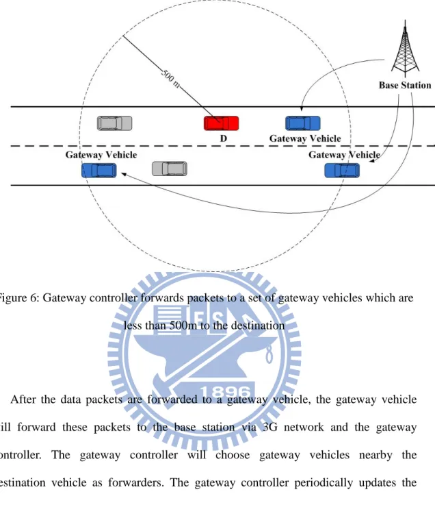
Figure 6: Gateway controller forwards packets to a set of gateway vehicles which are less than 500m to the destination
After the data packets are forwarded to a gateway vehicle, the gateway vehicle will forward these packets to the base station via 3G network and the gateway controller. The gateway controller will choose gateway vehicles nearby the destination vehicle as forwarders. The gateway controller periodically updates the gateway vehicles’ position. The forwarding decision of the gateway controller server depends on whether the distance between gateway vehicles and the destination vehicle is less than 500 meters. If there are many gateway vehicles’ distance less than 500 meters, all of those gateway vehicles will be selected as the forwarders. And the packets will be delivered to the destination vehicle via V2V. It could enhance the probability of successfully forwarding data packets to the destination vehicle. However, if there is no gateway vehicle forwarding data packets to the destination
15
vehicle, the gateway controller will drop the data packets. As shown in Fig. 6, three gateway vehicles will receive the data packets from the base station.
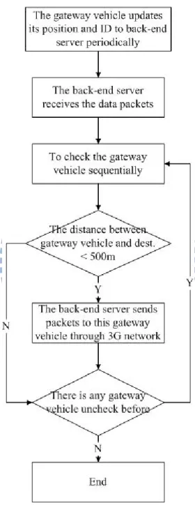
Figure 7: The flow chart of the back-end server forwarding a packet to the gateway vehicle
16
Fig. 7 shows the flow chart of the back-end server forwarding a packet to the gateway vehicle. If there is no gateway vehicle whose distance to destination vehicle is within 500 meters, the back-end server will drop those data packets. On the other hand, if there is more than one vehicle that meets this condition, the back-end server will record all of those gateway vehicles and forward the packet to them. The gateway vehicle will broadcast the packet to destination vehicle.
17
Chapter 4
Simulation
In this section, we evaluate the performance of MGRP using ns2 simulator [9] (version 2.34). We compare MGRP with the traditional position-based routing protocol GPSR [10] routing protocol, and analyze the relationship between the percentage of gateway vehicles and the success delivery ratio.
4.1 Simulation Environment
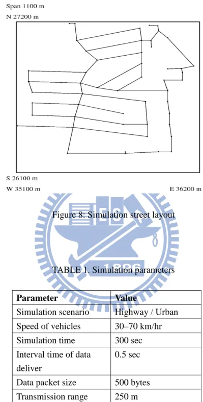
We perform the simulation on a real street map, captured from TIGER database (Topologically Integrated Geographic Encoding and Reference System) [11]. We simulated the MGRP within two scenarios, highway and urban. The urban street layout is within a 1100m*1100m area as shown in Fig. 8. There are totally sixty-one roads and 150 vehicles. We offer 10 CBR flows and the packet size is 512-byte. The simulation parameters are summarized in Table 1.
18
Figure 8: Simulation street layout
TABLE 1. Simulation parameters
Parameter Value
Simulation scenario Highway / Urban Speed of vehicles 30–70 km/hr Simulation time 300 sec Interval time of data
deliver
0.5 sec Data packet size 500 bytes Transmission range 250 m
19
4.2 Simulation Results
We first evaluate the relationship between the percentage of gateway vehicles and the packet delivery ratio for a scenario of 4km highway with four lanes and double directions. The results are shown in Fig. 9. We can see that when more vehicles play the role as mobile gateways, the packet delivery ratio increases significantly. Even in low density scenario (20 vehicles/km), the MGRP can achieve 80% packet delivery ratio if the percentage of the gateway vehicles is over 60%. When the percentage of gateway vehicles is 10%, the packet delivery ratio is down to 38%. Besides, the MGRP needs at least 70% gateway vehicles to reach the 100% delivery ratio in the low density scenario. On the other hand, the result shows that it can perform better in middle (30 vehicles/km) and high density scenarios (40 vehicles/km). In these cases, the MGRP needs just 30% of gateway vehicles to achieve nearly 100% delivery ratio. That is, if there are ten vehicles in the highway scenario, using our protocol just needs three vehicles to equip the OBU devices. Therefore, it does not need too much cost in this network architecture.
20
Now, we compare the performance of MGRP and GPSR Fig. 10 shows the packet delivery ratio versa the maximum speed. We can see that although the packet delivery ratios of both protocols decrease as long as the velocity of vehicles rises, our protocol still perform better, because the MGRP utilizes the 3G network and gateway controller to assist packet forwarding so that link disconnect due to high mobility can be greatly avoided.
Figure 10: Packet delivery ratio vs. maximum node speed
Fig. 11 shows the average hop count to the maximum speed. The results reveal that the average hop count increases when the velocity of vehicles rises regardless of MGRP or GPSR. The MGRP can keep count within 5 while the maximum hop count in GPSR is 8. It is because of the fact that we use 3G network to reduce the transmission hops. In addition, we limit the hop counts when the source vehicle intends to find a route to the gateway vehicle or destination vehicle.
0 0.2 0.4 0.6 0.8 1 1.2 30 35 40 45 50 55 60 65 70 P a ck et D el iv ery R a ti o ( % ) Maximum speed (km/hr) MGRP GPSR
21
Figure 11: Average hop count vs. maximum node speed
Fig. 12 shows the routing overhead versa the maximum speed. The results show that the packet overhead increases when the velocity of vehicles rises regardless of MGRP or GPSR. The packet overhead in MGRP is more than GPSR because we need to maintain the routing table. However, by establishing the routing table we can avoid the local maximum problem in GPSR. Furthermore, our method can decrease the total hop count to the destination node.
0 1 2 3 4 5 6 7 8 9 30 35 40 45 50 55 60 65 70 A ve rage H op C ou n t Maximum speed (km/hr) MGRP GPSR
22
Figure 12: Routing overhead vs. maximum node speed
Figure 13: Packet delivery ratio and overhead vs. hop count
Next, we compare the performance with our routing protocol MGRP and the routing method which utilizes the fixed RSUs to replace the mobile gateway vehicles. The RSUs are placed on intersections of the streets in Fig. 8. The number of intersections in the map is 51, that is, there are 51 RSUs setting in this example. And there are 150 vehicles equipped IEEE 802.11 interface. The packet delivery ratio,
0 5000 10000 15000 20000 25000 30000 35000 40000 30 35 40 45 50 55 60 65 70 P a ck et O v erh ea d Maximum speed (km/hr) MGRP GPSR 0 0.1 0.2 0.3 0.4 0.5 0.6 0.7 0.8 0.9 1 0 5000 10000 15000 20000 25000 1 2 3 4 5 P a ck et D el iv ery R a ti o P a ck et O v erh ea d Hop Count Overhead PDR
23
routing overhead and average hop count are compared between MGRP and the routing protocol with fixed RSU.
Figure 14: Packet delivery ratio vs. maximum node speed with fixed RSU and mobile gateway vehicle
Fig. 14 shows the packet delivery ratio versa the maximum speed. The packet delivery ratios of both protocols decrease as the speed of vehicles increases. Our protocol MGRP is better than the routing protocol with fixed RSU in terms of packet delivery ratio. Because the gateway vehicles in MGRP can move with the same direction with the other vehicles, it may increases the link lifetime.
Fig. 15 shows the routing overhead versa the maximum speed with fixed RSU and mobile gateway vehicle. The results show that the packet overhead increases when the velocity of vehicles rises regardless of MGRP or using fixed RSU. Our protocol MGRP is better than the routing protocol with fixed RSU in terms of routing overhead because mobile gateway may turn to other direction unexpected in some situations. It may cause the control messages increasing when finding another route path.
0 0.2 0.4 0.6 0.8 1 1.2 30 40 50 60 70 P a ck et D el iv ery R a ti o ( % ) Maximum speed (km/hr) MGRP FixRSU
24
Figure 15: Routing overhead vs. maximum node speed with fixed RSU and mobile gateway vehicle
Figure 16: Average hop count vs. maximum node speed with fixed RSU and mobile gateway vehicle
Fig. 16 shows the average hop count to the maximum speed with fixed RSU and mobile gateway vehicle. The results reveal that the average hop count increases when the velocity of vehicles rises regardless of MGRP or the method of using fixed RSU.
0 5000 10000 15000 20000 25000 30000 35000 40000 30 40 50 60 70 P a ck et O v erh ea d Maximum speed (km/hr) MGRP FixRSU 0 1 2 3 4 5 6 7 30 40 50 60 70 A ve rage H op C ou n t Maximum speed (km/hr) MGRP FixRSU
25
The result shows the hop count is similar regardless MGRP or the method of using fixed RSU. The reason is that both of those methods use 3G devices forwarding packets, so it can decrease the total hop counts.
26
Chapter 5
Conclusions
In this paper, the position-based routing protocol, called mobile gateways routing protocol, (MGRP) has been proposed for vehicular ad hoc networks in city environment. We utilize a part of vehicles as mobile gateway vehicles equipped with the OBU which can forward the data packets through interfaces of 3G or IEEE 802.11. Other vehicles without 3G interface can forward the packets through wireless network to mobile gateway vehicles, then using 3G interface to forward packets to the gateway controller. Finally, the gateway controller will forward the packets via mobile gateway vehicles nearby the destination vehicle. We design the routing protocol suitable for this hybrid network architecture and it decreases the total hop counts and the probability of links disconnection obviously. The simulation results show that MGRP performs better than the traditional position-based routing protocol GPSR.
27
References
[1] C. E. Perkins and P. Bhagwat, “Highly Dynamic Destination-Sequenced Distance-Vector Routing (DSDV) for Mobile Computers,” Special Interest Group
on Data Communication (SIGCOMM), Aug. 1994, pp.234–244.
[2] Y. Ding and L. Xiao, “SADV: Static-node-assisted adaptive data dissemination in vehicular networks,” Vehicular Technology, vol. 59, no. 5, Jun. 2010, pp. 2445-2455.
[3] C. C. Hung, H. Chan, and E. H. K Wu, “Mobility pattern aware routing for heterogeneous vehicular networks,” Wireless Communications and Networking
Conference (WCNC), Apr. 2008, pp. 2200-2205.
[4] Y. Peng, Z. Abichar, and J. M. Chang, “Roadside-aided routing (RAR) in vehicular networks,” IEEE International Conference on Communications (ICC), Jun. 2006, pp. 3602-3607.
[5] R. He, H. Rutagemwa, and X. Shen, “Differentiated reliable routing in hybrid vehicular ad-hoc networks,” IEEE International Conference on Communications
(ICC), May 2008, pp. 2353-2358.
[6] N. Brahmi, L. Boukhatem, N. Boukhatem, M. Boussedjra, N. D. Nuy, H. Labiod, and J. Mouzna, “End-to-end routing through a hybrid ad hoc architecture for V2V
28
and V2I communications,” Ad Hoc Networking Workshop (Med-Hoc-Net), Jun. 2010, pp. 1-8.
[7] J. Luo, X. Gu, T. Zhao, and W. Yan, “A mobile infrastructure based VANET routing protocol in the urban environment,” IEEE International Conference on
Communications and Mobile Computing (CMC), Apr. 2010, pp. 432-437.
[8] C. Perkin, E. Belding-Royer, and S. Das, “Ad hoc on-demand distance vector (AODV) routing,” IETF Experimental RFC, RFC 3561, Jul. 2003.
[9] Network simulator. ns-2. http://www.isi.edu/nsnam/ns, 2011.
[10] B. Karp and H. T. Kung, “GPSR: Greedy perimeter stateless routing for wireless networks,” ACM/IEEE International Conference on Mobile Computing, Aug. 2000, pp. 243-254.