國 立 交 通 大 學
電信工程學系
碩 士 論 文
應用於平均負載之
移動式隨意網路繞徑協定
A Reactive Load-Balancing Routing Protocol
For Mobile Ad Hoc Networks
研究生:余建傑
指導教授:唐震寰 博士
中 華 民 國 九十五 年 九 月
應用於平均負載之移動式隨意網路繞徑協定
研 究 生:余建傑 Student:Jian-Jie Yu 指導教授:唐震寰 Advisor:Jenn-Hwan Tarng 國 立 交 通 大 學 電信工程 學 系 碩 士 論 文 A ThesisSubmitted to Department of Communication Engineering College of Electrical Engineering and Computer Science
National Chiao Tung University in partial Fulfillment of the Requirements
for the Degree of Master in Communication Engineering
September 2006
Hsinchu, Taiwan, Republic of China
應用於平均負載之移動式隨意網路繞徑協定
A Reactive Load-Balancing Routing Protocol
For Mobile Ad Hoc Networks
研 究 生:余建傑 指導教授:唐震寰
國 立 交 通 大 學 電 信 工 程 研 究 所
摘要
行動隨意網路(Mobile ad hoc network)具有無線多次跳點連 接(multi-hop)的特性, 選擇路徑時若沒有考慮無線網路的負載,可 能會使負載過度的集中在無線網路的某個區域,該區域容易塞車,形 成網路傳輸瓶頸,使得網路整體效能降低。在本篇論文中,我們設計 ㄧ個考量網路負載的繞徑協定,此繞徑協定可以偵測網路的負載情 況,進而避開無線網路中負載集中的區域,使負載平均分配在網路節 點中。如此可以更有效率的使用無線網路資源。 關鍵字: 移動式隨意網路, 平均負載
A Reactive Load-Balancing Routing Protocol
For Mobile Ad Hoc Networks
student:Jian-Jie Yu Advisor:Jenn-Hwan Tarng
Department of Communication Engineering National Chiao-Tung University
Abstract
An Ad Hoc mobile Network is an infrastructure-less mobile network that has no fixed routers; instead, all nodes are capable of movement and can be connected dynamically in an arbitrary manner. Communication between mobile nodes can be achieved by multi-hop routing protocols. If routing protocol for Mobile Ad-Hoc network does not balance the traffic load over the network, it may create congested area. These congested areas greatly degrade the performance of the routing protocols. In this paper, we propose a routing scheme that balances the load over the network by selecting a path based on traffic sizes. We present a simulation study to demonstrate the effectiveness of the proposed schemes. Simulation
results reveal that the new scheme greatly reduces packet latency.
致謝
本篇論文的完成,需要感謝我的指導教授 唐震寰博士,還有本實驗室 的博士後研究助理 莊秉文博士,秉文學長在程式碼的撰寫部分給予我極大 的協助,細心的教導使我獲益良多,同時也要感謝我的家人及實驗室同學給 我溫暖的支持, 在此謹以簡短的字句向他們致上最誠摯的謝意以及祝福, 謝謝大家。Table of Content
中文摘要……….……….…………Ⅲ Abstract………..……….Ⅳ 致謝……….……….Ⅵ Table of Content……….Ⅶ List of Figure………..…………Ⅷ CHAPTER 1 Introduction………..……1 CHAPTER 2Background and Related Works ………..…..62.1 Background 2.1.1 Problems caused by share channels in MANETs…….…..7
2.1.2 Collision domain in a MANET……….….10
2.2 Related Works 2.2.1 LBAR Routing Protocol………12
2.2.2 DLAR Routing Protocol………17
2.3 Research Motivation………...20
CHAPTER 3 The Proposed Routing Protocol for Mobile Ad Hoc Networks………...23
3.1 Load Estimation……….. .23
3.2 Route Discovery………....26
3.3 Route Recovery……….29
CHAPTER 4 Simulation Result and Analyses 4.1 Time-varying topology effect………31
4.2 Traffic load effects……….34
4.3 Node density effect………38
List of Figure
Fig 1-1 Infra-structure based network Fig 1-2 mobile ad hoc network
Fig 2-1carrier sense multiple access scheme with collision avoidance (CSMA/CA) mechanism
Fig 2-2 hidden terminal and exposed node problem Fig 2-3 The function of RTS/CTS and ACK mechanism
Fig 2-4 Example of collision domain determination: (a) link constraints regard to link a; (b) collision domain of link a.
Fig 2-5 DLAR route selection algorithm
Fig. 3-1 Flow chart of the proposed AOLB routing protocol Fig 3-2 Packet format of proposed Hello message used by AOLB Fig 3-3 Packet format of proposed RREQ message used by AOLB Table 4-1. General configuration of simulation parameters
Fig 4-1 Averaged packet delay vs. waypoint pause time by using AODV, AOLB, DLAR, and LBAR
Fig 4-2 Packet delivery ratio vs. waypoint pause time by using AODV, AOLB, DLAR, and LBAR.
Fig 4-3 Averaged packet delay vs. packet transmission ratio by using AODV, AOLB, DLAR, and LBAR.
Fig 4-4 Packet delivery ratio vs. packet transmission rate by using AODV, AOLB, DLAR, and LBAR.
Fig 4-5 Averaged packet delay vs. number of traffic flows by using AODV, AOLB, DLAR, and LBAR.
Fig 4-6 Packet delivery ratio vs. number of traffic flows by using AODV, AOLB, DLAR, and LBAR.
Fig 4-7 Packet delivery ratio vs. node density by using AODV, AOLB, DLAR, and LBAR.
Fig 4-8 Packet delivery ratio vs. node density of traffic flows by using AODV, AOLB, DLAR, and LBAR.
CHAPTER 1 Introduction
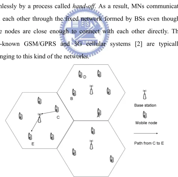
There are currently two categories of mobile wireless networks. The first is known as the infrastructure based network [1]. As depicted in Fig. 1-1, this kind of networks is composed by inter-connected fixed facilities, which are known as base stations (BSs). A mobile node (MN) can access the network by connecting with a selected BS when it is within the BS’s radio coverage. When the MN travels out of the coverage of connecting BS and moves into the coverage of other BSs, the MN can still access the network through a newly selected BS instead of the original BS seamlessly by a process called hand-off. As a result, MNs communicate with each other through the fixed network formed by BSs even thought these nodes are close enough to connect with each other directly. The well-known GSM/GPRS and 3G cellular systems [2] are typically belonging to this kind of the networks.
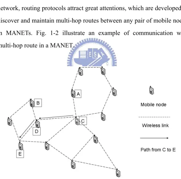
The second type of mobile wireless network is the mobile ad hoc networks (MANETs) [1]. A MANET is a collection of MNs forming a temporary inter-connected network without the aid of fixed BSs or any centralized administration regularly available in infra-structure based networks. In a MANET, every node can connect with neighboring nodes dynamically in an arbitrary manner and can function as routers, which are used to forward packets for other mobile nodes. In such a dynamic network, routing protocols attract great attentions, which are developed to discover and maintain multi-hop routes between any pair of mobile nodes in MANETs. Fig. 1-2 illustrate an example of communication with multi-hop route in a MANET.
Fig 1-2 mobile ad hoc network
due to the nature of time-varying network topologies and shadowing effect [20] of neighboring obstacles decrease the stability of the multi-hop routes. Besides, nodes share bandwidth with their neighbors in MANETs, which means the available bandwidth of a specified radio link is correlated with traffic loads of neighboring nodes and their adjacent links. Even if a radio link is stable from propagation effects point of view, the performance of the radio link is still strongly influenced by congested traffics of interfering radio links nearby. So the routing protocols for MANETs have to adapt to the unexpected variation of network topologies and traffic loads of links and nodes.
Several mobile ad hoc routing protocols have been proposed to overcome time-varying network topologies of MANETs. These protocols are generally categorized as either proactive or reactive protocols. Proactive routing protocols [4-6] keep track of feasible routes beforehand for every node pair even the node pair does not require a route. Due to the routes are discovered and maintained in advanced, these protocols experience minimal delay for initializing communication but result large control overheads. Since both bandwidth and battery power are scarce resources in MANETs, large control overhead is a major limitation to proactive routing protocols.
On the other hand, reactive routing protocols [7-11] explore a route only when a node pair desires one. Therefore, these protocols require less control overheads. When a source has a packet to transmit, it invokes a route discovery process to find a multi-hop route to the destination. The route remains valid until the destination is reachable or until the route is
wireless ad hoc communication.
Above all, traditional ad-hoc routing protocols, either proactive or reactive, are mainly based on shortest path routing algorithms (or minimum hop counts) to determine the routes for the requesting node pairs. Although it is intuitive and simple, the traffic congestion problem caused by unbalanced traffic loads of MANETs can not be solved by shortest path routing algorithms. With dynamical occurrence of traffic loads between node pairs, each node in a MANET would carry on different processing load, which results in different processing delay at each node. Besides, in a contention-based wireless communication network, which is commonly used for MANETs [1], the traffic loads of neighboring nodes are correlated with the probability of collisions as well as the averaged communication delay of radio channels used by these nodes. In general, a highly-contented radio channel would lead to large communication delay and massive packet loss between neighboring nodes. Therefore, if a multi-hop route is formed by highly-loaded intermediate nodes or highly-contented radio channels, it would be suffered from large end-to-end data transmission delay even though the number of hops is small. To overcome above problem, a load-balanced ad hoc routing protocol is required to avoid traffic congestion in MANETs.
In this paper, we proposed a load-balanced ad hoc routing protocol to avoid creating highly contented areas and to distribute traffic load evenly throughout the network. The basic idea of proposed protocol is keeping track of the total size of contenting traffic loads within each shared radio channel, as the main route selection criterion. Based on the former concept, we design a load-sensitive ad hoc routing protocol named as Ad
hoc On-demand Load-Balancing Routing Protocol (AOLB) to discover multi-hop routes formed by lightly loaded nodes and links, which decreases average packet transmission delay and packet loss rate for MANETs.
CHAPTER 2 Background and Related Works
2.1 Background
Currently, ad hoc routing protocols lack load-balancing capabilities [13]. Thus, they often fail to provide good service quality especially in the presence of a large volume of traffic since the network load concentrates on some nodes and radio links resulting in a highly congested environment. Several load aware routing protocols [14-16] for ad hoc networks has been proposed in recent years. Most of these protocols use the total number of packets or the sum of packet sizes buffered in the processing queue of network node as the main load metric. This metric works well in wired networks, because the bottleneck of communication performance in wired networks is the limited processing power of nodes, which can be reflected by queue sizes. However, this metric does not reflect the impact of an important factor: channel contention from neighbor nodes. In a wireless ad hoc network, nodes contend for the shared channel, which causes access delay and collision at MAC layer. To consider the effects of contention among mobile nodes in a MANET, the IEEE 802.11 MAC protocol [17] is selected in this research. The reason of choosing IEEE 802.11 protocol is not only this protocol has been commonly used for constructing MANET system nowadays, but also the proceeding ad hoc network standard, the IEEE 802.11s standard [18], will adopt a similar MAC protocol as well. In the following paragraphs, the problems caused by shared channel in ad hoc network are presented, and the collision domain of a specified radio link in a MANET is defined in order to estimate the total traffic load of shared
channels.
2.1.1 Problems caused by share channels in MANETs
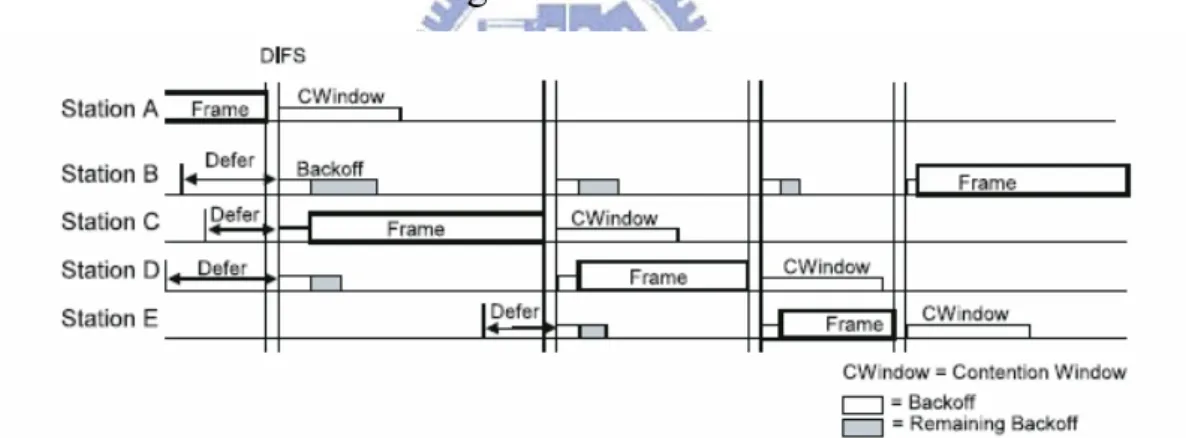
Since MANETs inherently use a shared medium for communication, the MAC protocols’ primary goal is to avoid collisions, while maintaining good efficiency, delay, and fairness [1]. The IEEE 802.11 MAC layer protocol is actually a carrier sense multiple access scheme with collision avoidance (CSMA/CA) mechanism. As depicted in Fig. 2-1, a host senses the medium before its intended transmission. If the channel is busy, the host postpones the transmission. Otherwise, the host will wait for a randomly determined backoff time period and then transmit data frames. The backoff mechanism is designed to avoid collision.
Fig 2-1 carrier sense multiple access scheme with collision avoidance
(CSMA/CA) mechanism
Since the radio channel is shared and contended, two well-known problems, including hidden terminal problem and exposed node problem
[1], would occur. These two problems increase the probability of data
frame collisions and the blocked time of nodes due to transmission by neighboring nodes in a MANET. In order to solve these problems, an
optional mechanism of IEEE 802.11 protocol, the IEEE 802.11 DCF protocol, employs add-on control frames, the request-to-send (RTS) and clear-to-send (CTS) control frames, to prevent collisions in advance [19]. Although this mechanism effectively avoids collisions by preventing simultaneous transmissions among neighboring nodes, it expends the scope of contention area. Due to the shared radio channels are managed by MAC protocol, an estimation model for traffic load analysis of MANETs, which takes into account the interactions at the MAC layer, is required.
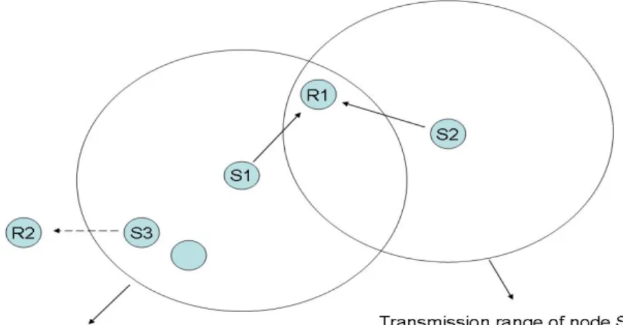
The hidden terminal problem refers to the collision of packets at a receiving node due to the simultaneous transmission of those nodes that are not within the direct transmission range of the receiver. Collision occurs when both nodes transmit packets at the same time without knowing about the transmission of each other. For example, consider Figure 2-2. Here, if both S1 and S2 transmit to node R1 at the same time, their packets collide at node R1. This is because both nodes S1 and S2 are hidden from each other as they are within the direct transmission range of each other and hence do not know about the presence of each other.
The exposed terminal problem refers to the inability of a node, which is blocked due to transmission by a nearby transmitting node, to transmit to another node. Consider the example in Figure 1-6. Here, if a transmission from node S1 to another node R1 is already in progress, node S3 cannot transmit to node R2, as it concludes that its neighbor node S1 is in transmitting mode and hence it should not interfere with the on-going transmission.
Fig 2-2 hidden terminal and exposed node problem
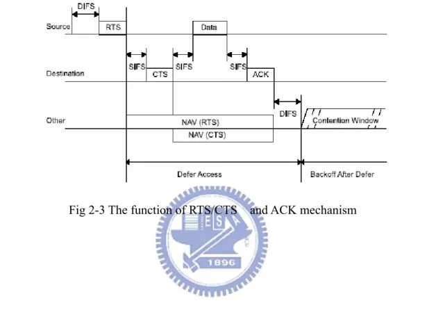
In order to solve these problems, IEEE 802.11 protocol, the IEEE 802.11 DCF protocol, employs a series of mechanism to prevent collisions in advance . (1) Every node transmits a control packet named request-to-send (RTS) before it transmits the data packet. An RTS packet includes the source address, destination address and the expected transmit delay of the data packet. If the channel is free, the destination node replies with a control packet named clear- to-send (CTS). The intension of RTS/CTS handshake is to reserve the channel for transmitting the data packet. Whenever other nodes overhear these RTS and CTS messages, they will delay their possible channel access according to the duration field in the RTS and CTS packet. (2) A mobile node senses the channel before each transmission, even if the channel is free, the host keeps sensing the channel for a specified time period to avoid any contender. (3) the destination node checks the error detection field in the received packet field and an acknowledgment (ACK) packet is replied if no error is found. If the sender node does not receive the ACK packet, it
retransmits the packet until an ACK is received or the number of retransmission is over seven. The function of RTS/CTS mechanism is shown in Fig. 1-7. The RTS/CTS handshake is proven to be effective for resolving the hidden terminal problem.
Fig 2-3 The function of RTS/CTS and ACK mechanism
2.1.2 Collision domain in a MANET
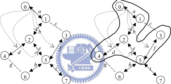
Here we define the collision domain of a specified radio link as a set of radio links formed by this link and all other links that have to be inactive for avoiding collision when the specified link is transmitting data frames. Practically, for any MAC protocol, given the topology of the network, a list of collision domains can be computed or determined experimentally. Fig. 2-2 depicts an example of collision domain determination. The solid arrows denote active links used to forward data traffics. The dashed lines connect nodes that can receive each other’s transmissions. Finally, the dotted arrows represent transmission
constraints for avoiding collisions. Fig 2-4(a) shows that IEEE 802.11 DCF protocol protects both ends of a link. When the link a between node 0 and node 1 is active, none of the other links connected by a constraint should be active in order to avoid a collision. Fig. 2-4(b) depicts the collision domain corresponding to link a under the assumption of using IEEE 802.11 DCF protocol. In a MANET, each link has a collision domain that may partially overlap with the collision domains of other links. 0 1 2 4 6 5 7 3 0 1 2 4 6 5 7 3 a b c d e f g h i a b c d e f g h i
Fig 2-4 Example of collision domain determination: (a) link constraints regard to link a; (b) collision domain of link a.
As a result, all links in a collision domain share the communication medium as well as a single radio channel. Once the collision domains are determined, the traffic load of a specified link should be estimated by the summation of all traffic flows passing through the collision domain of this link. We adopt this model to develop the traffic load estimation method in the proposed protocol, which is presented in Chapter 3.
2.2 Related Works
The load balance routing protocols for ad hoc wireless networks are proposed in [13-15]. According to how the traffic size is estimated, the load balance routing protocols can be divided into two classes. The first class of protocol estimates the utilization of node interface queue as the load metric. The Dynamic Load-Aware Routing Protocol (DLAR) [14] is one of notable protocol belonging to this class. The second class of protocol keeps track of traffic flows throughout the network. One notable example is the Load-Balanced Ad Hoc Routing Protocol (LBAR) [5]. These protocols are depicted in following subsections.
2.2.1 LBAR Routing Protocol
The algorithm has four components: Route Discovery; Path Maintenance; Local Connectivity Management; Cost Function Computation.
Route discovery
The route discovery process is initiated whenever a source node needs to communicate with another node for which it does not have a known route. The process is divided into two stages: forward and backward. The forward stage starts at the source node by broadcasting setup messages to its neighbors. A setup message carries the cost seen from the source to the current node. A node that receive a setup message will forward it, in the same manner, to its neighbors after updating the cost based on its load condition. In order to prevent looping when setup messages are routed, all
setup messages are assumed to contain a route record, including a list of all node IDs used in establishing the path fragment form the source node to the current intermediate node. The destination node collects arriving setup messages within a route-select waiting period, which is a predefined timer for selecting the best-cost path. The backward stage begins with an ACK message forwarded backward towards the source node along the selected path, which is called the active path. If a link on the selected path breaks, the ACK message is discarded and an error message is sent backward along the path fragment to the destination. The destination node will then choose another path, which does not contain any previous broken links. When the source node receives an ACK message, it knows that a path has been established to the destination and then starts transmission.
Path maintenance
In wireless networks, nodes are allowed to move freely, which causes dynamic topology changes and route invalidity. If the source node, an intermediate node on the active path or the destination node moves out of the communication range, an alternate path must be found. If the source node moves away from the active path, packets would not be able to be related to downstream neighbors. In this case, the source has to reinitiate the route discovery procedure to establish a new route to the destination. When either the destination node or some intermediate node moves outside the active path, path maintenance will be initiated to correct the broken path. Once the next hop becomes unreachable, the next hop becomes unreachable. The node upstream of the broken hop
notification of a broken links, the destination node picks up an alternative best-cost partial route passing through the node propagating the error message and then sends an ACK message to the initiator of the error message. If the destination has no alternative path passing through the node sending the error message, the destination picks up another route and sends an ACk message to the source. The source will use this new route to send data packets if it still has data to send. By then, a new active path is defined. In the worst case, where the destination has no alternate paths, it propagates an error message to the source and lets it restart route discovery.
Local connectivity management
Nodes learn about their neighbors in one of two ways. Whenever a node receives a broadcast from a neighbor, it updates its local connectivity information in its neighborhood table to ensure that it includes this neighbor. In the event that a node has not send data packets to any of its active neighbors within a predefined timeout, hello_interval, it broadcasts a hello message to its neighbors, containing its identity and load condition. This hello message is prevented from being rebroadcast outside the neighborhood of the node. Neighbors that receive this packet update their local connectivity information in their Neighborhood tables. Receiving a broadcast or a hello from a new neighbor, or failing to receive consecutive hello messages from a node previously in the neighborhood, is an indication that the local connectivity has changed. If hello messages are not received from the next hop along an active path, the upstream active neighbors using that next hop send notification of link failure and the path maintenance protocol is invoked.
Cost computation
The cost function is used to find a path with the least traffic so that data packets can be transmitted to the destination as fast as possible while achieving the goal of balancing load over the network. The following definitions are used:
․active path : a path from a source to a destination , which is followed by packet along this selected route.
․active node :a node is considered active if it originates or relays data packets or is a destination.
․ inactive node:a node is considered inactive if it is not along an active path.
․ cost: minimum traffic interference is proposed as the metric for best cost.
In wireless ad hoc networks, transmitters use radio signals for communication. Communication among mobile nodes is limited within a certain transmission. Within each such range, only one transmission channel is used, covering the entire available bandwidth. To transmit data, mobiles within the same range have to sense for other transmissions first and then gain access permit and transmit only if no other node is currently transmitting. Unlike wired networks, packet delay is not caused only from traffic load at the current node, but also by traffic load at neighboring nodes. To assess best cost, the term total load is used as an means to reflect traffic load at the node. Such activity information can be
interference is defined as the sum of neighboring activity of the current node. During the routing stage, nodal activity and traffic interference are calculated at every intermediate node along path from source to destination. When the destination receives routing information, it choose a path, which has minimum cost.
They define the local load of node n (L).
․Activity Ai: number of active paths through node i. the
greater the value of activity is, the more traffic passing through node i would be.
․Traffic interference : i
i i j j
TI TI A
∀
=
∑
, which is the sum ofactivity of neighboring nodes of node I, where j is a neighboring node of node i.
․Cost Ck : cost of route k,
k
(
i i)
(
i ij)
i k i k j
C
A TI
A
A
∈ ∈ ∀
=
∑
+
=
∑
+
∑
Where I is a node on path k other than source and destination. (Every path with identified source-destination pair includes same source and destination, so for simplicity, activities of source and destination are excluded.) j is a neighboring node of node i.
This is a generic cost function, which is based on the assumption that packets are of the assumption that packets are of the same size and traffic is at a constant rate. Other alternative functions ca be also used without impacting the generality of the proposed routing protocol.
2.2.2 DLAR Routing Protocol
DLAR builds routes on-demand. When a route is required but no information to the destination is known, the source floods the route request packet to discover a route. When nodes other than the destination receive a non-duplicate route request, they build a route entry for the <source, destination> pair and record the previous hop to that entry. This previous node information is needed later to relay the route reply packet back to the source of the route. Nodes then attach their load information (the number of packets buffered in their interface) and broadcast the route request packet. After receiving the first route request packet, the destination waits for an appropriate amount of time to learn all possible routes. In order to learn the routes and their quality , the destination node accepts duplicate route requests received from different previous nodes. The destination chooses the least loaded route and sends a route reply packet back to the source via the selected route.
In this protocol, intermediate nodes cannot send a route reply back to the source even when they have route information to the destination. To utilize the most up-to-date load information when selecting routes and to minimize the overlapped routes which cause congested bottlenecks, DLAR prohibits intermediate nodes from replying to route requests. During the active data session, intermediate nodes periodically piggyback their load information on data packets. Destination node can thus monitor the load status of the route. If the route is congested, a new and lightly loaded route is selected to replace the overloaded path. Routes are hence reconstructed dynamically in advance
route discovery process except that the destination floods the packet to the source of the route, instead of the source flooding to the destination. The source, upon receiving route request packets, selects the best route in the same manner as the destination. The source does not need to send a route reply, and simply sends the next data packet using the newly discovered route.
A node can detect a link break by receiving a link layer feedback signal from the MAC protocol, not receiving passive acknowledgment, or not receiving hello packets for a certain period of time. When a route is disconnected, the immediate upstream node of the broken link sends a route error message to the source of the route to notify the route invalidation. Nodes along the path to the source remove the route entry upon receiving this message and relay it to the source. The source reconstructs a route by flooding a route request when informed of a route disconnection.
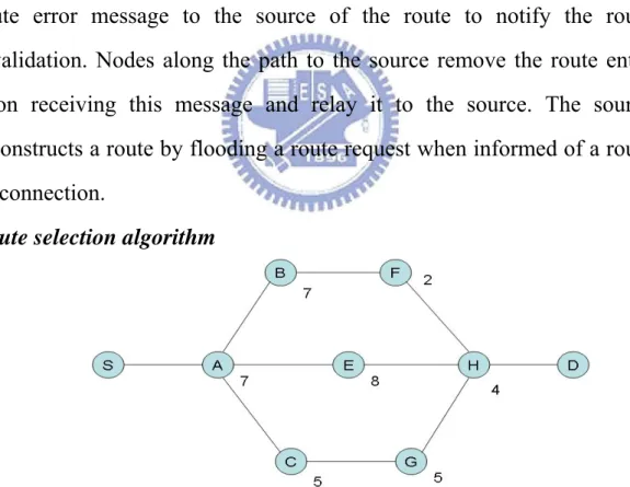
Route selection algorithm
Fig 2-5 DLAR route selection algorithm
They introduce three algorithm in selecting the least loaded route. Using Figure 2 as an example network to describe each scheme.
intermediate node and selects the route with the least sum. If there is a tie, the destination selects the route with the shortest hop distance. When there are still multiple routes that have the least load and hop distance, the path that is taken by the packet which arrived at the destination the earliest between them is chosen. In the example network, route I has the sum of 20 (i.e., 7+7+2+4=20), route j has the sum of 19(i.e., 7+8+4=19), and route k has the sum of 21(i.e., 7+5+5+4=21). Therefore, route j is selected and used as the route.
DLAR scheme 2 is similar to scheme 1. However, instead of using the sum of number of packets queued at each intermediate node’s interface as in scheme 1, scheme 2 uses the average number of packets buffered at each intermediate node along the path. We can use the shortest dealy as a tie breaker if needed. Considering the ezample in figure 2 again, route I has the average value of 5(i.e., 20/4=5), route j has the value of 6.67(i.e., 19/3=6.67), and route k has the value of 5.25(i.e.,21/4=5.25). route I is thus selected.
DLAR scheme 3 consider the number of congested intermediate nodes as the route selection metric. Basically, it choose the route with the least number of intermediate nodes that have their load exceeding the
threshold τ . In this example, if τ is five route I has two intermediate
node (i.e., nodes A and B) that have the number of queued packets over the threshold, route j has two ( i.e., nodes A and E), and route k has one (i.e., node A). Hence, route k is selected using this algorithm. This scheme applies the same tie breaking rule as in scheme 1.
2.3 Research Motivation
Although several ad hoc routing protocols have been proposed, these protocols only consider traffic load of node but do not precisely calculate total traffic load of shared radio channels within specified collision domains. In DLAR the load metric of a node is defined as the number of packets buffered in the node, and the load metric of a route is the summation of the load metrics of the nodes on that route. The DLAR protocol does not optimally reflect the actual load since buffered packets may vary in size. Besides, this protocol does not consider the effect of contention/collision within shared channels. In LBAR, the load metric of a node is the total number of routes flowing through the node and its neighbors. Although LBAR takes traffic loads of contending neighbors into account, it is not optimal since it does not account for the various traffic sizes of each route.
In this research, we aim to propose a load-balanced ad hoc routing protocol, whose load metric of multi-hop route considers the effect of contention/collision within shared channels. A novel load estimating method is defined. Based on the proposed method for load estimation, the proposed routing protocol explores the least load routes, which provide high packet delivery rate and sufficient decrease the packet latency for all source and destination pairs in MANETs.
CHAPTER 3 The Proposed Load-Balanced Routing
Protocol
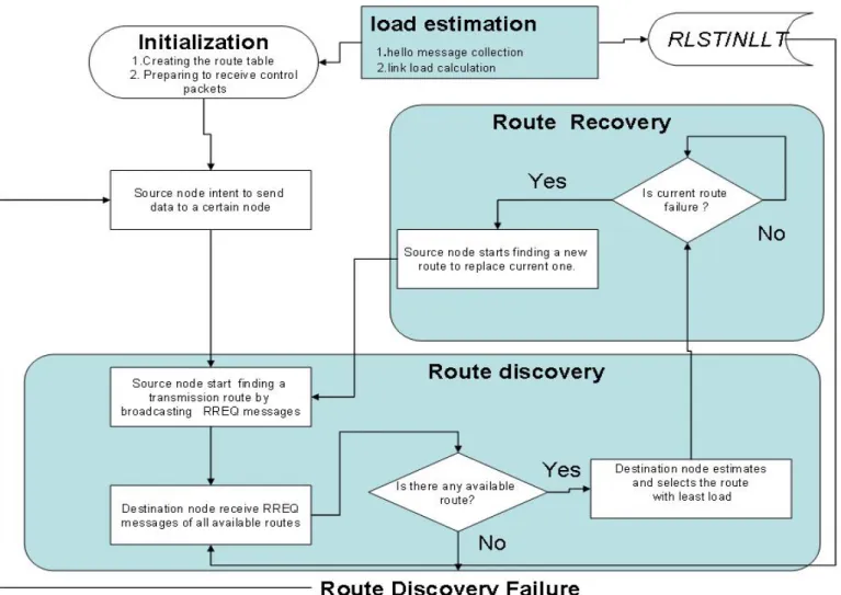
The proposed load-balanced routing protocol is named as Ad-hoc On-demand Load-Balancing (AOLB) routing protocol. This protocol aims to increase packet delivery rate and decrease packet delay by discovering the least loading route using a novel load estimation method and a load-aware path finding algorithm. In Fig.3-1, the flow diagram of the AOLB routing protocol is depicted. Three major processes form the proposed protocol, which are Load Estimation, Route Discovery, and
Route Recovery. The following paragraphs are given to describe the details of these processes.
Fig. 3-1 Flow chart of the proposed AOLB routing protocol, 3.1 Load estimation process
In this process, each node of MANETs begins to estimate the link loads of radio links to its neighbors. To reflect the effect of contention in
shared channels, here the link load of a given radio link i at time t, Li(t), is
equal to the ratio of averaged traffic size pass through the collision domain of radio link i to the maximum data rate of this link. Assuming the symmetric MAC protocol is used in MANETs, therefore, the link load is estimated by
i q p i
C
t
T
t
T
t
L
(
)
=
max[
(
),
(
)]
(1),where Ci is the maximum data rate of link i; p, q are identifiers of
adjacent nodes connected by link i; Tp(t) and Tq(t) are summation of
averaged traffic size pass through node p, node q and their neighboring nodes within a time window δ, which is represented by
1 0
1
( )
( (
)
(
))
m m m g k g NT t
δS t k t
S t k t
δ
− = ∈=
∑
− Δ +
∑
− Δ
(2), whereSm(t-kΔt) represents the total traffic size pass through node m between
time t-(k+1)Δt and time t-kΔt and is defined by
)
(
)
(
)
(
p
r
p
s
p
S
m=
m+
m (3),where rm(p) and sm(p) denotes traffic size received by node m and
transmitted by node m between time p-Δt and time p, respectively;
δ is the total number of unit time steps of time window to calculate
the averaged traffic size;
Δt represents a unit time step length;
Nm is a node set formed by all neighboring nodes of node m;
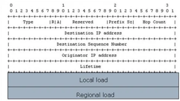
In order to keep track of the link load between a given node and its neighbors, each node periodically broadcasts Hello message (HELLO) attached with traffic size passed through itself, the Local Load field calculated from Eq.(3), and the summation of traffic sizes passed through
its neighbors and itself, the Regional Load field calculated from Eq.(2). Fig. 3-2 depicted the packet format of proposed Hello message. With the received HELLOs, the receiving node is aware of traffic loads nearby and determines link loads of adjacent radio links. The detail procedure of load estimation process is presented by following steps:
Fig 3-2 Packet format of proposed Hello message used by AOLB
Step 1: Counting traffic size of every node at each unit time. The averaged traffic size passed through each node at recently unit time, including the received traffic and the transmitted traffic, is temporarily counted by Eq.(3) and recorded. Then, the averaged traffic size of that node would be filled in the Local Load field of the broadcasting HELLO message.
Step 2: Determining total traffic size of every node and its neighbors. With the received HELLO messages, averaged traffic sizes of all
neighboring nodes together with their IP addresses and timestamps are recorded in a table, named as Regional Loading Status Table (RLST) at each receiving nodes. With the memorized traffic sizes of neighboring nodes in RLST, the receiving node further evaluates the total traffic size of its neighbors and itself by Eq.(2) with predefined time window δ. The summation of traffic sizes is filled in the Regional Load field of HELLO messages and broadcasted to its neighbors per unit time.
Step 3: Estimating and recording the link loads. Due to the summation of
averaged traffic sizes of a specified node p, says Tp(t), and that of its
neighboring node q, says Tq(t), are determined, the link load of radio link
between node p and q is estimated by Eq.(1). Therefore, the link loads of all adjacent radio links are estimated and recorded in a table, named as Neighbor Link Load Table (NLLT), which is used to keep track the up-to-date link loads of radio links to its neighbors for both route discovery and route recovery processes. The link loads are estimated per unit time and the NLLT are periodically updated.
3.2 Route Discovery Method
This process executes a path-finding algorithm to discover the multi-hop route with minimum route load for a specified source and destination pair. The following steps present the detail procedures. In steps 1-3, multiple available routes are explored at the destination node. The load of each available route is also determined within this stage. In
node. With the intention of transmitting packets at source node, the source node, intermediate nodes, and the destination node perform the following steps:
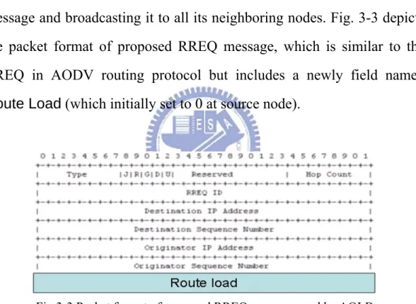
Step 1: Source node starts to find out the least loaded route by broadcasting the RREQ message. To fulfill dynamically occurred route request for a specified source and destination pair, the source node initiates a route discovery process by generating a Route Request (RREQ) message and broadcasting it to all its neighboring nodes. Fig. 3-3 depicts the packet format of proposed RREQ message, which is similar to the RREQ in AODV routing protocol but includes a newly field named Route Load (which initially set to 0 at source node).
Fig 3-3 Packet format of proposed RREQ message used by AOLB
Step 2: Intermediate nodes restrict the flooding of RREQ message to reduce control overhead. An intermediate mobile node might receive multiple RREQs and rebroadcast these messages during the route discovery process. To decrease the control overhead caused by the flooding RREQ messages in MANETs, the intermediate mobile nodes
rebroadcast only the RREQ with the minimum value in Route Load field among the received RREQ messages.
Step 3: Nodes calculate route load of eligible routes from the source to the intermediate node. Before the intermediate node rebroadcasts the selected RREQ message, it needs to recalculate the Route Load. Here the route load of a specified multi-hop route r at time t is given by
]
),
(
max[
)
(
i r rt
L
t
i
P
RL
=
∀
∈
(4),where i denotes the link within the route r and Pr represents the link set
containing all links of the route r. As we mentioned in load estimation process, the link loads are collected from the NLLT of intermediate nodes along this route.
Step 4: Destination node select the route with the minimum Route Load. With multiple RREQs continually arriving at destination node, the destination node only receives the RREQs within a time window, which starts from the first arrival RREQ. After the destination node determines the one with the minimum route load, it creates a Route Reply (RREP) message formatted similarly in AODV protocol for responding with the RREQ. Then the RREP is forwarded to the neighbor from whom the selected RREQ was sent.
entries in the route tables. When an intermediate node receives the RREP message, it sets up the forward entry to the destination node in its route table. After processing the RREP message, the intermediate node forwards the RREP message toward the source node along the reverse route through which the selected RREQ message passed.
Step 6: Source node discovers the selected route and start to transmit data. The source node receives the RREP and sets up the route table to the destination node. The least loaded route with minimum route load is discovered by a specified RREQ and the forward entries of route tables from source node through intermediate nodes to the destination are set up by the replying RREP.
3.3 Route Recovery
Due to the time-varying topologies of MANETs, the availability of the connecting routes would change with time. In order to react the change of route availability, a Route Recovery process is proposed.
Step 1: Using the periodically hello message to detect the load condition
AOLB routing protocol uses the Hello message to monitor link load to all neighbors. All mobile nodes periodically send Hello messages which containing the load information to its neighbors. Whenever a node receives a broadcast from a neighbor, it calculates interference load which is from its neighbor nodes. The interference load will periodically updates to react the change of load condition.
Step 2: Route error message, and route rediscover
If a link breakage is detected, a Route Error message is send to the source node from the mobile node that detects the link breakage occurrence. When the source node receives the RERR message it will rediscover a new least loaded route by flooding newly issued RREQs to the destination node.
CHAPTER 4 Simulation Results and Analysis
In order to evaluate the performance of proposed AOLB routing protocol, the NCTUns network simulator [22] is employed. For comparing between the proposed AOLB protocol and related works, the AODV, DLAR and LBAR routing protocols are also included. As to the physical layer and MAC layer protocols, the IEEE 802.11b PHY and IEEE 802.11 DCF MAC protocol are selected. All of chosen protocols are evaluated on a simulated free-space propagation environment with a large-scale median path-loss model and a small-scale fading model . A traffic generator, which transmits UDP packets with specified constant packet delivery rate, is used to obtain the communication performance between the specified S-D pair. The random waypoint mobility model is chosen to emulate the moving behavior of each mobile node. Here, two significant metrics are considered to determine the performance of load-balanced MANET routing protocols in our simulations.
z Averaged packet delay (APD): the averaged packet delay is the averaged end-to-end delay time of all received data packets that are transmitted from the source nodes to the destination nodes. Only end-to-end packet delays of successfully delivered packets are considered in our simulations.
z Packet delivery ratio (PDR): the packet delivery ratio P is the ratio of total number R of received data packets at destination nodes to the total number S of data packets transmitted by source
nodes during a specified time period, that is, P=R/S. In most of the simulation cases, the number R is less than the number S due to packet loss along the wireless multi-hop route.
In this paper, effects of time-varying topologies, traffic loads, and node density on APDs and PDRs are investigated and simulated. In most of simulation cases, 50 nodes are randomly distributed in a restricted 1500m × 300m rectangular area at the beginning. For each simulation case, total of 5 tests were made, where each test lasts for 500 seconds and samples the number of received packets and their packet delays per second in order to calculate both APD and PDR. The configurations of simulation parameters for most of simulation cases are depicted in Table 4-1.
Table 4-1. General configuration of simulation parameters
Parameters Parameter assigned values
Area of operation (m2) 1500 × 300
Number of nodes 50
Initial topology Randomly assigned
Moving speed of nodes (m/s) 10 Optimal radio channel capacity (Mbps) 2 Variance of small-scale fading effect (db) 20 Transmission range of single radio link (m) 200 Received power sensitivity and threshold (db) -74
Simulation time (sec) 500
4.1 Time-varying topology effect
routing protocols with different degree of node mobility as well as time-varying topology of MANETs. Total of 30 traffic flows are simultaneously generated with 5 packets/second packet transmission rate. These traffic flows are further divided into four groups by the size of transmitted packet. They are 8 flows with 128 bytes per packet, 8 flows with 256 bytes per packet, 7 flows with 512 bytes per packet, and 7 flows with 1024 bytes per packet. In order to grade the degree of node mobility, the random waypoint mobility model with configurable waypoint pause time [21] is chosen to emulate the moving behavior of mobile nodes. The waypoint pause time here indicates the waiting time period between the time while the mobile node arriving a specified waypoint, and the time while it starts to leave the waypoint. The smaller the pause time, the higher degree of node mobility would be. Fig. 4-1 and Fig. 4-2 show the APD and PDR versus node pause time by using selected routing protocols, respectively. 0 1 2 3 4 5 6 0 200 400 600
Waypoint Pause Time (secconds)
A ve rage P ac ket D el ay ( se conds ) AODV AOLB DLAR LBAR
Fig 4-1 Averaged packet delay vs. waypoint pause time by using AODV, AOLB, DLAR, and LBAR.
0.5 0.55 0.6 0.65 0.7 0.75 0.8 0 100 200 300 400 500 600
Waypoint Pause Time (seconds)
Pa ck et D el iv er y R at e AODV AOLB DLAR LBAR
Fig 4-2 Packet delivery ratio vs. waypoint pause time by using AODV, AOLB, DLAR, and LBAR.
It is found that the proposed AOLB protocol always performs shortest APD in all test cases and provides highest PDR when the node pause time is larger than 300 seconds. From Fig. 4-1, there is a trend that the APD decrement of AOLB to other protocols increases with the increasing of waypoint pause time. The largest APD decrements of AOLB are 4.14 seconds, 0.88 seconds, and 1.28 seconds to AODV, DLAR, and LBAR protocols, respectively, when the pause time is 500 seconds. Fig. 4-2 shows that the PDR improvement of AOLB over other protocols increases at the same time. The best PDR improvement of AOLB are 12.59%, 4.38%, and 6.51% over AODV, DLAR, and LBAR protocols, respectively. This phenomenon indicates that the AOLB protocol provides better performance than other protocols when the degree of node mobility is low. Due to in highly variant network topologies, it is hard to lower down the probability of route breakage and difficult to balance traffic loads in nature, so that either the AOLB nor other load-balanced routing
shortest-path based AODV protocol.
4.2 Traffic load effects
In this simulation, we investigate the traffic load effects on the performance of load-balanced routing protocols. Two simulation scenarios are considered. In the first scenario, the traffic load effect caused by the increasing packet transmission rate on each traffic flow is investigated. Total of 30 traffic flows are simultaneously generated with a specified packet transmission rate. These traffic flows are further divided into four groups by the size of transmitted packet similar to prior simulations presented in section 4.1. The waypoint pause time of each moving path of nodes is 250 seconds. To vary traffic load of each flow, packet transmission rates are increased from 1 packets/second to 8 packets/second. Fig. 4-3 and Fig. 4-4 show APD and PDR versus packet transmission rate by using AODV, DLAR, LBAR, and AOLB protocols, respectively.
0 1 2 3 4 5 6 0 2 4 6 8 10
Packet Transission Rate(packets/sec)
A ver ag e P ack et D el ay (s ec o nd s) AODV AOLB DLAR LBAR
Fig 4-3 Averaged packet delay vs. packet transmission ratio by using AODV, AOLB, DLAR, and LBAR.
0.3 0.4 0.5 0.6 0.7 0.8 0.9 0 2 4 6 8 10
Packet Transmission Rate (packets/seconds)
P ac ke t D eliv er y R ate AODV AOLB DLAR LBAR
Fig 4-4 Packet delivery ratio vs. packet transmission rate by using AODV, AOLB, DLAR, and LBAR.
From Fig. 4-3, it is found that the averaged packet delay increases with packet transmission rate by whatever the selected routing protocol. This phenomenon is caused by the increasing packet contention time at each intermediate node due to the increment of traffic loads. By
comparing all simulated protocols, the proposed AOLB protocol always selects the routes pass through minimum loaded collision domains, which effectively decreases packet contention time as well as APD. The APD using proposed AOLB protocol is better than those of AODV, DLAR, and LBAR for all transmission rates. The largest APD decrements of AOLB are 4.01 seconds, 1.44 seconds, and 2.19 seconds to AODV, DLAR, and LBAR protocols, respectively, when the transmission rate is 8 packets/second. It is noted that the AODV protocol, which is based on shortest path algorithm, cannot evenly distribute traffic loads as a result producing traffic congestion and performing highest APD in all test cases. Fig. 4-4 shows that the packet delivery ratio decreases with the increasing of packet transmission rate. The AOLB protocol provides best PDR when the packet transmission rate is larger than 3 packets/second. The average improvements of PDR are 11.9%, 3.12%, and 6.24% over AODV, DLAR, and LBAR, respectively.
In the second scenario, the traffic load effect caused by the increasing number of traffic flows is investigated. For a specified number of traffic flows, all traffic flows are evenly divided into four groups by the size of transmitted packet, including 128 bytes per packet, 256 bytes per packet, 512 bytes per packet, and 1024 bytes per packet. These traffic flows are simultaneously generated with 5 packets/second packet transmission rate. Four numbers of traffic flows are considered, including 10 flows, 20 flows, 30 flows, and 40 flows. Fig. 4-5 and Fig. 4-6 show APD and PDR versus number of traffic flows by using selected routing protocols, respectively.
0 1 2 3 4 5 6 7 0 20 40
number of traffic flows
A ver ag e P ack et D el ay ( se c) AODV AOLB DLAR LBAR
Fig 4-5 Averaged packet delay vs. number of traffic flows by using AODV, AOLB, DLAR, and LBAR.
0.3 0.4 0.5 0.6 0.7 0.8 0.9 1 0 20 40
number of traffic flows
P ac ke t D eliv er y R ate AODV AOLB DLAR LBAR
Fig 4-6 Packet delivery ratio vs. number of traffic flows by using AODV, AOLB, DLAR, and LBAR.
From Fig. 4-5, it is found that the averaged packet delay increases with number of traffic flows. This phenomenon is also caused by the increasing of packet contention time when the whole traffic load in the
AOLB protocol has minimum APD in all test cases. Although AOLB perform much better APD than AODV, however, the AOLB cannot significantly improve other related works, DLAR and LBAR, when the number of traffic flows is quite small (10 flows) or large (40 flows). The largest APD decrements of AOLB are 3.54 seconds, 0.39 seconds, and 0.71 seconds to AODV, DLAR, and LBAR protocols, respectively, when the number of traffic flows is 30 flows. Due to the major difference between AOLB and these related works is the estimation method of load metric for selecting multi-hop route, this phenomenon indicates that estimation method of load metric would not be the critical factor for load-balanced routing protocol in lightly-loaded or fully-loaded MANETs. Fig. 4-6 shows that the packet delivery ratio decreases with the increasing of packet transmission rate. The average improvements of PDR are 11.4%, 3.48%, and 7.45% over AODV, DLAR, and LBAR, respectively.
4.3 Node density effect
Here, to investigate network performance with different node density,
50 mobile nodes are configured to randomly move within a 600m×300m,
900m × 300m, 1200 × 300m, 1500m × 300m, 1800m × 300m, and
2100m×300m area. Total of 30 traffic flows are simultaneously generated
with 5 packets/second packet transmission rate. Fig. 4-7 and Fig. 4-8 show the APD and PDR versus node density by using selected routing protocols, respectively.
0 1 2 3 4 5 0 100 200 300
node density (per myriare)
A ver ag e P ack et D el ay (s ec) AODV AOLB DLAR LBAR
Fig 4-7 Packet delivery ratio vs. node density by using AODV, AOLB, DLAR, and LBAR. 0.3 0.4 0.5 0.6 0.7 0.8 0.9 0 100 200 300
node density(per myriare)
P ac ke t D eliv er y R atio AODV AOLB DLAR LBAR
Fig 4-8 Packet delivery ratio vs. node density of traffic flows by using AODV, AOLB, DLAR, and LBAR.
Fig. 4-7 shows that the largest APD decrements of AOLB are 3.54 seconds, 0.39 seconds, and 0.71 seconds to AODV, DLAR, and LBAR protocols, respectively. From Fig. 4-8, AOLB provides the best PDR
comparing to other protocol. The averaged improvement ratios of PDR using AOLB to the PDR using AODV, DLAR, and LBAR are 10.72%, 2.24%, 6.22%, respectively. There is a trend that the PDR decreases with the decreasing of node density. This is caused by the averaged hop count of routes is large when node density is low, which results in high probability of packet loss and lowers down the PDR.
CHAPTER 5 Conclusions
In this paper, a load-balanced ad hoc routing protocol, the Ad-hoc On-demand Load-Balancing (AOLB) routing protocol, for MANETs is proposed. The protocol is based on a novel link/route load metric to evenly distribute traffic loads in MANETs, which aims to avoid packet contention/collision in collision domains. In AOLB protocol, every node in an MANET maintains both a routing table and a data sheet with estimated traffic load of its belonging collision domain, which slightly increases the computational complexity. Simulation results by changing the degree of node mobility, the total traffic load within a network, and node density indicate that the AOLB leads to significant averaged packet delay decreases about 1 to 4 seconds over AODV and averaged packet delivery ratio increases about 7% to 14% over AODV. The improvement of AOLB also dominates over that of DLAR and LBAR. It is found that with considering total traffic size of shared radio channels to estimated load metric can significant improve the performance of MANETs. With proposed load estimation and route finding processes, the AOLB protocol can effectively discover least loaded multi-hop routes, and yields good performance when the traffic load is large or the nodes move slowly.
Reference
[1] C.E. Perkins, Ad hoc networking, Addison-Wesley,2001.
[2] Milica Pejanovic , “On optimization of 3G cellular systems deployment”, ITU IMT-2000 seminar Warsaw , October 2001.
[3]B. Sklar, “Rayleigh fading channels in mobile digital communication systems part I: characterization,” IEEE Communications Magazine, July 1997.
[4]C.E Perkins and P. Bhagwat, “Highly Dynamic Destination-Sequence Distance-Vector Routing (DSDV) for Mobile Compyters”, Computer and communication ,Oct. 1994,pp.234-244.
[5]C. –C Chiang, “Routing in Clustered Multihop,Mobile Wireless Networks with Fading Channel” Proc. IEEE SINGAPORE CONFERENCE – IEEE
SICON’97.Apr.1997,pp.197-211 .
[6]Tsu-Wei Chen and Mario Gerla, “Global State Routing: A new Routing Scheme for Ad-Hoc Wireless Networks” IEEE International conference on communications (ICC), 1998.
[7]A. Iwata, C.-C. Chiang, G. Pei, M. Gerla, and T.-W. Chen, “Scalable Routing Strategies for Ad Hoc Wireless Networks”, IEEE Journal on selected Areas in Communications, Special Issue on Ad-Hoc Networks, Aug. 1999,pp.1369-79.
[8]C-K. Toh, “A novel distributed routing protocol to support Ad hoc mobile computing” proc. 1996 IEEE 15th Annul International Phoenix Conference Computer and communication, Mar. 1996, pp. 480-86
[9]C-K. Toh, “Long-lived Ad-Hoc routing based on the concept of Associativity” Internet
Engineering Task Force—IETF Draft, Mar. 1999.
[10]David B. Johnson, Davis A. Maltz, “The Dynamic Source Routing Protocol for Mobile Ad Hoc Networks” IETF Draft, Oct. 1999.
Vector Routing”, IETF Draft, Oct.1999.
[12] Perkins, C., Belding-Royer, E., and Das,S., “Ad hoc On-Demand Distance Vector (AODV) Routing,” rfc3561.txt (2003).
[13] J.Macker and S. Corson,” Mobile Ad Hoc Networks (MANET):Routing Protocol Performance Issues and Evaluation Considerations,” IETF RFC 2501, January 1999. [14] S. –J. Lee and M.Gerla, ‘Dynamic Load-Aware Routing in Ad Hoc Networks,’
in Proceedings of IEEE ICC’01, Helsinki,Finland,Jnne 2001.
[15]H. haassanein and A. Zhou, “Routing with Load Balancing in Wireless Ad Hoc Networks,” in Proceedings of ACM MSWiM,Rome,Italy,July 2001.
[16]K. Wu and J. Harms, “Load sensitive Routing for Mobile Ad Hoc Networks,” in Proceedings of IEEE ICCCN’01,Scottsdale,AZ,USA,October 2001.
[17] IEEE 802.11 Standard for Wireless LAN, 1999 [18][802SEC]802.11s press release
http://grouper.ieee.org/groups/802/secmail/msg07954.html
[19]S. Xu and T. Saadawi , “ Does the IEEE 802.11 MAC Protocol Work Well in Multihop Wireless Ad Hoc networks?” IEEE Common. Mag., June 2001.
[20] Barclay, L. W.,”Propagation of radio waves” [21]N. Mitrou “Networking 2004: 3rd” [22] http://nsl.csie.nctu.edu.tw/nctuns.html