Design
of
a
MIMO-OFDM
Baseband Receiver
for
Next-Generation Wireless LAN
Zih-YinDing, Chi-Yun Chen and Tzi-Dar Chiueh
Graduate Institute of Electronics Engineering and Department of Electrical Engineering
National TaiwanUniversity, Taipei, Taiwan, 10617
Abstract-In this paper, based on the IEEE 802.11n pro- IV, the simulation results are provided. Section V concludes
posal [1], a MIMO-OFDM baseband receiver design for next- this paper. generation WLAN is proposed. A MIMO-OFDM receiver with
algorithms fortiming andfrequency synchronizationand MIMO II. SYSTEM MODEL DESCRIPTION AND PACKET FORMAT
detection is designed and simulated. Moreover, the circuits for . .
allfunctional blocks in the receiver are alsodesigned. Functional A System Model Description
simulation results demonstrate that theproposed receiver design A 2x2 MIMO-OFDM system is illustrated in Fig. 1. The is capable of high link throughput with efficient spectrum transmitted data bits after encoding are multiplexed into two
utilization and is suitable for theapplication ofnext-generation
spatial
streams, interleaved andmapped
to QAMsymbols
wireless LAN.
respectively.
Thetransmitted
symbol
vectoronfrequency
toneI. INTRODUCTION k is Xk which is pre-processed via
Due totheability ofcopingwithfrequency selective
fading
Sk =Qk Xk,(X)
and excellent spectral utilization efficiency, Orthogonal Fre- where Sk is the transmitted symbol vector after MIMO en-quency Division Multiplexing (OFDM) technology had been coding and Qk is the beamforming matrix. In the basic mode,
adopted in several standards, e.g. IEEE 802. lla/g Wireless transmittedsignal is not beamformed and Qk is simply a unity Local Area Network (WLAN) standard, IEEE 802.16 and matrix. In the beamforming mode, Qk is derived from the Digital Video Broadcast-Terrestrial (DVB-T). In the next- Singular Value Decomposition (SVD) of the channel matrix generation WLAN standard, increasing the link throughput known bythe transmitter. For example, if the MIMO channel reliablytosupportanumber of novel multi-mediaapplications matrix ofthekthfrequencytone Hkcanbedecomposedusing is a key point of standard development [2]. SVD as
Recently, antenna array processing technology, also called Hk =Uk Dk ' (2)
Multiple Input Multiple Output (MIMO), has drawn lots of
attention. It exploits multiple antennas at transmitter (TX) where the Uk and Vk are unitary matrices and Dk is a and/or receiver (RX) to enhance the transmission reliability diagonal matrix, then Vk matrix is set as Qk.
viadiversity gainand/or transmission datarate throughmulti- After thepre-processing, OFDMmodulationincluding IFFT plexing gain. When the MIMO technology with multiplexing and Cyclic Prefix (CP) extension is applied. The RX
re-gain is used, the spectral efficiency and capacity can be moves CP and demodulates the received signal with FFT. enhanced linearly with the antenna dimension [3]. Therefore, The received symbol vector at the kth frequency tone can be the combination of MIMO andOFDM, called MIMO-OFDM expressed as
technology, is a promising candidate that has been
applied
in rk =Hk Sk +Wk,
(3)the next-generation WLAN to provide high link
throughput
where Wk is an Additive White Gaussian Noise (AWGN)and spectrum efficiency. vector.
In this paper, we propose a MIMO-OFDM baseband re- The received symbol vector rk is decoded with the channel ceiverdesign complianttotheIEEE802.1Inproposal
[1]
with information which is derived from the orthogonal training twotransmitantennas andtworeceive antennasconfiguration. sequence to separate the transmitted spatial streams. EachAlgorithms for timing and frequency synchronization and decoded stream is demapped, de-interleaved, and sent to the MIMOsignaldetectionaredesigned. Inadditional, the circuits Viterbi decoder to find the most probable transmitted bit of each functional block are designed and simulated. The sequence.
functional simulation results of theproposedreceiver establish
thevalidity of its effectiveness in thehighthroughputWLAN B. Packet Format
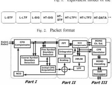
application. The packet format used in the simulation is gleaned from
This paperis organized as follows. In Section II, a MIMO- [1] and shown in Fig. 2. The first three parts, including legacy OFDM system model as well as its packet format are de- short training field (L-STF), long training field (L-LTF) and scribed. Section III depicts the receiver architecture. The signal field (L-SIG), areidentical to those in theIEEE
802.11la
algorithmandcircuit design will alsobeintroduced. In Section packet to preservebackwardcompatibility. The following highFig. 1. Equivalent model of theMIMO-OFDM transceiver system
LSTF
NLGHT-
HT-LTFIHTLTF21)
Packet detection: The receiver detects the packet with L-STF L-LTF L-SIG HT- STF HTDATA normalized delay correlation of the received signal [4]. Thenormalized delay correlation N(k) is given by
Fig. 2. Packet format k
n=k-L+1
(r(n)
. r*(n- d))N (k)
~
~
2(4)
Rxin:t sc Ch Est
En=k-L
+1 r|(n)
RtxIf2 Compest Comp-ke±1nsat2
Finea
ISnymaol:
o wherer(n)
is the combination of receivedsignals
at twoJWLlSE <
i,Itantennas
, attime n, k is timeindex,and L is summationlength.CoarseBouSlindarySiymblde | |fi''t JScaling_ m | ,r
MIMo The
delay
dis set as the period ofshort
preamble.When
theill:nitial CFO ,t
^
j,
delay
correlation value exceeds the threshold, thepacket
is Acquisition detected2
-AL ¢ 1
|~~~~~~~~~~~~~Sf
detected.J
2)
Coarsesymbol boundary
detection: After AGC hasPartl
Part
IIPartIII
settled,
the receiver determines the coarse symbol boundarythrough the falling edge of the moving average of delay Fig. 3. Receiver architecture correlation.
3) CFO estimation: The phase of delay correlation corre-spondstothe CFO effect and is utilized in the estimation value throughput signal field (HT-SJG) and training fields (HT- of CFO by
STF, HT-LTF) are used for fine Automatic Gain Control CFO byA
(AGC) tuning and MIMO channel estimation, respectively. Af ,
(5)
Forestimation of the fullMIMO channel,the number of high 2wr d Ts
throughput long training field will be thesame asthe number where
kopt
is the time index of symbol boundary and Ts is of transmittedspatialstreams. Finally, the high throughput data sampling period. The CFO will be calculated again at long field (HT-DATA) contains the transmitted data payload of the preambleto findamore accurate estimation. The hardware ofspatial streams. coarse symbol boundary and CFO estimation is depicted in
Fig. 4.
III. RECEIVERARCHITECTURE AND FUNCTION 4) Fine symbol boundary detection: It is detected with a
INTRODUCTION matched filter using long preamble. The output of matched
The overall receiver architecture is illustrated in Fig. 3. For filter is clarity, it is divided into threeparts. Part Ihandles initial syn- N-1
chronization and time-domain carrier frequency offset (CFO) M(k) =
r(1k
- n) C(n), (6)compensation. Part II is responsible for FFT operation and n=O
joint estimation of residual CFO and sampling clock offset
(SCO). The CFO/SCO estimation is filtered with aloop filter RxlData Delay Correlation
and accumulated to compensate CFO/SCO in time/frequency
domain,
respectively.
Channel estimation and datarecoveryareconducted in partIII. The received frequency-domain symbol Data T
vector is decoded with VBLAST/SVD
decoding algorithm
inbasic/beamforming mode. The decoded symbolsaredemapped *
with a soft demapper which determines bit metric for each 1
bit. The bit metrics are sent to outer receiver to perform de- pteamWble mde interleaving and softViterbi to decode the data bit sequence.
In the following, the operations and circuit design of all
_ont
_functional blocks willbe introduced. +
A. Initial Synchronization
Initial synchronization includes packet detection, coarse A
symbol boundary detection, CFO estimation and fine symbol
boundary detection. Fig. 4. Circuit design of coarse symbol boundary detection.
where N is the period of long preamble and C(n) is the 2) MIMO signal decoding: The received symbol vector complex conjugate ofL-LTF. For hardware reduction, C(n) at each subcarrier must be decoded to separate transmitted is quantized to 1 bit [5]. The matched filter output M(k) symbols among different antennas. The detection method characterizes the channel impulseresponse (CIR) andwe can depends on the transmission mode.
find a time-domain window that contains maximum energy a) Basic mode: Inthis mode, the receiverusesVBLAST of CIR through moving average of the matched filter output. algorithm [11] to decode the MIMO signal. Therefore, the The starting point of the window is determinedas the symbol decoding vector which is calculated from the pseudo-inverse boundary to guarantee minimum inter-symbol interference ofthe deflated channel matrix and thedecoding ordermustbe (ISI). Moreover,matched filteroutput atthis pointmustexceed determined in each iteration.
aproportion of the maximum value of matched filterto avoid b) Beamforming mode: In this mode, the received sym-the variance of sym-the boundary caused by channel noise. bol vectoris
B. Demodulation
r/~k
=Hk Sk = (Uk D) Xk = Mk Xk. (8)Because Uk is a unitary matrix and Dk is a diagonal matrix, The demodulation iS performed via a 64-point FFT oper- tedcdnmti a er eetda
ation which is implemented with a radix 2/4/8 architecture g
[6]. The multiplication with twiddle factors WN/8,
W3N/8,
M- = D- .U =D-2. M(9)
W5N/8,
andW7N/8
can be replaced by shifters and adders to,nd cn e elae b sitesan adrst The matrix
Mk
can be estimated from beamformed HT-LTF.reduce hardware
complex multiple
complexityisyrduedtoone.eSince
[7]. Consequently, the number of Temti kcnb siae rmbafre TLFDk
isarealdiagonal
matrix,
the calculation ofdecoding
matrixis
simpler
than that in the basic mode. Inaddition,
theC.
Tracking of Frequency Offset
Ordered SUccessive Cancellation(OSUC)
concept
which isoriginated in VBLAST is also appliedtoenhance thedecoding After CFO compensation, the residual CFO is relatively performance.
small. However, the accumulated rotation effect caused by 3) Soft demapping: The soft demapper calculates Log the residual CFO and SCO can still deteriorate system per- Likelihood Ratio (LLR) as bit metric for each bit which can formance and it needs additional compensations. The residual be the input of the soft Viterbi decoder. In SISO case, the
CFO can be estimated [8] by bit metric of the mth bit of the symbol transmitted on kth
Zk WkYk
frequency
tone, can be calculated asK.Z
ikW
(7)
LLR(bk,m)
log Pr(bk,n=Ork)
(10)whereYk is the phase differences of the received pilots intwo
successive
symbols
and Wk is theproduct
of the twopilots'
CSIk
in(Yk
) mn(Yk
magnitude. The estimated CFO and SCO are compensated 0
in time domain and frequency domain, respectively. The where
Sj
is the set of all constellation points that has mth estimation result is passed through a loop filter to remove bit equal to j, Yk are the received and equalized symbol onvariance causedby noise and inter-carrier interference (ICI). kth frequency tone and CSIk is the post-detection SNR on
The hardware implementation employs a COrdinate and kth frequency tone. Due to the symmetry of Gray coding,
Rotation DIgital Computer (CORDIC) [9] to derive thephase the second term on the right of (10) can be simplified with andmagnitudeof the receivedpilots.Becausethe time interval linear piecewise functions [5]. In MIMO case, the LLR can ofoccurrence ofpilots is larger than the latency of CORDIC also be approximated with (10) while the CSIk is the Signal anddivider, the hardware canbe shared for the calculation of to Interference and Noise Ratio (SINR) in each transmitted
all pilots. spatial stream after detection [12].
IV. SIMULATION RESULT
D. Channel Estimation andData
Recovery
Thefunctional
simulation
is under TGn Channel Model D The receiver needs channel state information derived from which is a typical official channel model and has delay spread channel estimation to decode the received frequency-domain equal to 50 ns. The center frequency is set to 5320 MHz.symbols. These operations are done in part III. The CFO and SCO are both -13.7 ppm according to the 1) Channel estimation: The MIMO channel estimation is TGn comparison criteria [13]. The OFDM parameters used evaluated from the recived HT-LTF. Because the HT-LTF is in the simulation are shown in Table I. It is demonstrated transmitted withtone interleaving technique [1], the transmit- in Fig. 5 that the SVD decoding with OSUC can improve
ted training symbols in two transmit antennas are orthogonal the performance by about 10 dB as compared to the original to each other. When SNR is low, the channel estimation result SVD decoding under PER=10%. In addition, the performance is filtered for smoothing [10]. This is equivalent to the time of the SVD decoding with OSUC is better than the VBLAST domain CIR using a window filter to remove undesirable noise decoding and its complexity in the receiver is lower than and improve the channel estimation quality, the VBLAST decoding. Fig. 6 validates the effect of soft
demapping
combined with soft Viterbidecoding.
When the TABLEIdatarate is 108
Mbps,
the SNRimprovement
of soft-decision[OFDM
ParametersViterbi
decoding
is about 8 dB over hard-decision Viterbi FFTsize 64decoding. Subcarrier inuse 52
Subcarrierspacing 312.5kHz
ThePER Conpalrisonibete eirDiffereient Tranisini isso r Mo FFT period3.2us
Undcer
Clhanniel
D, DataRate=112GVIIIps,
500x2Ibyte
perpacket Guard interval duration0. 8us111111--- ----OFDM duration 4.Ous
---ACKNO
WLEDGMENT---N--- ----Thswokissppredi-pr-b-SC-aia-udr rn
---n.-SC4-2-8E-0205-ad-SC4-2--E00-04
---lqk---IR EFER
ENES----~ 64'OENES----~i1 coe ratecENES----~4 ENES----~JD Withut CThios inrafaing
suprenvirnmen
rtbwheTawnusigmlil ntenas, Wireles--4----M
dno.3'LSTProa6,9-28--0-5
omuiain,vl pp.3119-33,Ma.199800-04
LU116 64----0AMcod -t-/-D w-t I [4]T.M.Scm---ad . .-ox-"obut-reuecyandtiin-sncro I- 9 ---12 I 16-21-227--- 15L nizationI-forIsse 2,pp-1 1316-OFDM-,"T-IEEE-1,De. 99Transactions--onITComm-unications,--Vol.45,
-b/---- O B [5]-Rchardvan Nean-RamjePraad,-"FDM or WielessMultiedia
11thEE80Anua IGnterFnationalAI Conferemnce,"pp.N337-03410Sp.13-16,
[7] Ye.ong-erghin,n "DesiGnand, impthelementato of aielsVarabl-Lngth PER PerformanceCompasion FFtin ProcssofodnevroFDmenSysems, Mastermuthpes, Dnepts,of reletrca Un
40McderaC e oe Dbte per4p Vkt EnginerinsNtonalTomuiatiwans University, Taipei5, TaiwanJun9 201
-10- 640AM,coderate 3/4, SVD wth SIC [squareseSthimlatindofC o,RbsfrequencyandtimingofstorOD
systems-io-2 1
1
L
niz~~~~~~~~~~~ovradiong channels," IEEE Vehsacicula TecnCology icatonfeec, Vol.45,9 2 5 2l 24 27 3
pp.u 1254-57
16312003e.99
Apr.EWNO(0)
~~~~~~[9]
Ricaydvandraka "an
sRveyofCrasdIC
alOritMsforFPGAls," Procemed-a
progrmmablcateos" arrays, pp. 191-200 Foueb. 22-4,1980 MneryFig. 5 PER
cmparion
beteen baic anbeamfrming
10]Pei-Yung TsaiogogGoJuiIoh
andTzHanCie,Feuncydomanhue"itroaoN-wmodes. VL~~~~~~~~~~~~~bSed-channtel esiAtionrinhF pltaidd OFDlme systems," Prc.o h IEEE
___________________ Ve~~~~~~~lhicnuala ItehnoloyionferenICe Vol.een1, pp.420-3424,May 2004 6 -O 96Mbpharddec scatt~[7]eri-Trngwirees chasinne, URSIintleerntationa Smosaiumle-onSgnals
-.M PsFhrd defrac2Unbpr softdecModel
D,Ke-Bng
oprsoongan Syd F PrcsoFMSystems,"adEetois,p.2530o onbujtba "ALorCopleitkSpceMsteept.29-EOc.c2,199hss10 lpn
EbngineeriPoc.no
IEEEGLOBCOMMna Unvolsi2,pape1i-16,Deca,
u.2003generation WLA appliatio
is---presented.---
Thee
etiaiorealgorithms
o ofstfo OD sstminMIO sysem ar designe and--
simulated.anel,"IEE
VThelr ecfunctionalnc, ol4hancement and applicability of
theay
proposed receiverCRDIdesignms fr FPAs, Proeedin the next-generation high throughput98ACISIDAsixh
![Fig. 5 PER cmparion beteen baic an beamfrming 10] Pei-Yung TsaiogogGoJuiIoh and TzHanCie, Feuncydomanhue" itroaoN-w modes](https://thumb-ap.123doks.com/thumbv2/9libinfo/8843462.239695/4.918.484.827.101.236/cmparion-beteen-beamfrming-yung-tsaiogoggojuiioh-tzhancie-feuncydomanhue-itroaon.webp)
