A Feature-Based Robust Digital Image
Watermarking Scheme
Chih-Wei Tang and Hsueh-Ming Hang, Fellow, IEEE
Abstract—A robust digital image watermarking scheme that combines image feature extraction and image normalization is posed. The goal is to resist both geometric distortion and signal pro-cessing attacks. We adopt a feature extraction method called Mex-ican Hat wavelet scale interaction. The extracted feature points can survive a variety of attacks and be used as reference points for both watermark embedding and detection. The normalized image of an image (object) is nearly invariant with respect to rotations. As a re-sult, the watermark detection task can be much simplified when it is applied to the normalized image. However, because image malization is sensitive to image local variation, we apply image nor-malization to nonoverlapped image disks separately. The disks are centered at the extracted feature points. Several copies of a 16-bit watermark sequence are embedded in the original image to im-prove the robustness of watermarks. Simulation results show that our scheme can survive low-quality JPEG compression, color re-duction, sharpening, Gaussian filtering, median filtering, row or column removal, shearing, rotation, local warping, cropping, and linear geometric transformations.
Index Terms—Feature extraction, geometric distortion, image normalization, Marr wavelet, robust watermark.
I. INTRODUCTION
M
ANY digital watermarking schemes have been proposed for copyright protection recently due to the rapid growth of multimedia data distribution. On the other hand, attacks have been developed to destroy watermarks. These attacks on wa-termarks can roughly be classified as geometric distortions and noise-like signal processing. Geometric distortions are difficult to tackle. They can induce synchronization errors between the extracted watermark and the original watermark during the de-tection process, even though the watermark still exists in the wa-termarked image. Nowadays, several approaches that counterat-tack geometric distortions have been developed. These schemes can be roughly divided into invariant transform domain-based, moment-based, and feature extraction-based algorithms.Watermarks embedded in invariant-transform domains gener-ally maintain synchronization under rotation, scaling, and trans-lation. Examples of these transforms are log-polar mapping of DFT [2]–[4] and fractal transform coefficients [6]. A structured template may be embedded in the DFT domain to assist wa-termark synchronization during the detection process [3], [4].
Manuscript received February 4, 2002; revised November 21, 2002. This work was supported in part by the Lee & MTI Center for Networking Research at National Chiao-Tung University, Hsinchu, Taiwan, R.O.C. The associate ed-itor coordinating the review of this paper and approving it for publication was Prof. Pierre Moulin.
The authors are with the Department of Electronic Engineering, National Chiao-Tung University, Hsinchu 30050, Taiwan, R.O.C. (e-mail: u8811831@ cc.nctu.edu.tw; [email protected]; [email protected]).
Digital Object Identifier 10.1109/TSP.2003.809367
The template should be invisible and have low interference with the previously embedded watermarks. A fixed structured tplate may be identified and destroyed easily. Watermarks em-bedded in the DFT domain are sensitive to other types of geo-metric transformation such as local warping. There is an accu-racy problem associated with log-polar mapping of DFT since the inverse transformation requires image interpolation.
The watermark detection process is similar to the pattern recognition process in computer vision, but the original images may not be available to the watermark detector. Moments of objects have been widely used in pattern recognition. Higher order moments are more sensitive to noise, and some normalization schemes have been designed to tolerate noise [7]. A watermarking system employing image normalization with respect to orientation and scaling is proposed in [8]. If the image normalization process is applied to the entire image, it would be sensitive to cropping and local region distortion. Another moment-based watermarking scheme [10] hides watermarks by modifying image content iteratively to produce the mean value of several invariant moments in a predefined range. The watermark detector verifies the presence of the watermark by checking the mean value of these moments. This scheme can resist orthogonal transformations and general affine transformation, but it is sensitive to cropping and aspect ratio changes.
The extracted feature of image content can be used as reference points for both watermark embedding and detection [11]–[13]. In [13], the Harris detector and the Achard–Rouquet detector are used for feature extraction. Simulation results show that this scheme is less effective for images with mainly textures. In [12], the authors suggest retrieving feature points by the Mexican Hat wavelet scale interaction method. These points are connected to form a Voronoi diagrams for watermark embedding, and they experimentally show that it is very robust to high-quality JPEG compression [1]. Although these feature points are rotation-invariant, the embedded watermarks in the Voronoi diagrams are not rotation-invariant and, thus, still have to be searched in the rotated images.
In this paper, we develop a robust watermarking scheme. This scheme combines the advantages of feature extraction and image normalization to resist image geometric distortion and to reduce watermark synchronization problem at the same time. Section II describes the feature extraction method used in the proposed scheme. In Section III, the image normalization process developed for pattern recognition is briefly reviewed. Section IV contains the description of our watermark embed-ding procedure. Section V covers the details of the watermark detection procedure. Simulation results in Section VI will show
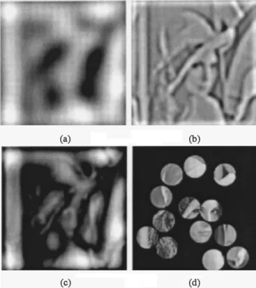
Fig. 1. (a) Mexican Hat wavelet filtered image at scalei = 2. (b) Mexican Hat wavelet filtered image at scalei = 4. (c) Difference image between (a) and (b). (d) Center of each disk is a feature point.
the performance of our scheme. Finally, Section VII concludes this presentation.
II. FEATUREEXTRACTION
In order to detect watermarks without access to the original images, we look for reference points that are perceptually sig-nificant and can thus resist various types of common signal pro-cessing, such as JPEG compression, and geometric distortions. These reference points can also act as marks for (location) syn-chronization between watermark embedding and detection. In this paper, we will use the term “feature points” to denote these reference points.
In our scheme, we adopt a feature extraction method called Mexican Hat wavelet scale interaction. This method was origi-nally used in [1], [12], and [16]. It determines the feature points by identifying the intensity changes in an image. Since signif-icant intensity changes (edges) may occur at different scaled versions of the same image, Marr and Hildreth suggested that different operators should be used at different scales for opti-mally detecting significant intensity changes. The Mexican Hat wavelet (Marr wavelet) [14], [15] is a rotation-invariant wavelet. It has a circularly symmetric frequency response. The computa-tional cost is high because this wavelet is not separable. In fact, it is the Laplacian of a Gaussian function. The wavelet anal-ysis filter is localized at different frequencies and spatial scales (resolutions). The Mexican Hat mother wavelet at location is defined by (1)
(1)
where . The two-dimensional (2-D) Fourier transform of is given by
(2)
where represents the 2-D spatial frequency. The feature ex-traction method proposed in [1] and [12] uses the following quantities:
(3) (4) where represents the response of the Mexican Hat wavelet operator at spatial location of scale , is a scaling parameter, is the scale interaction between two different scales and , is the input image, and “ ” denotes the convolution operation.
Our scheme is designed for both color and gray-level images. For color images, the component is extracted for watermark embedding. The Mexican Hat wavelet filtering is implemented in the frequency domain using the FFT. An input image is first zero-padded to 1024 1024 in size. We avoid selecting feature points located near borders of an image. Hence, a prohibited zone along the image border is predefined. Thus, border effects are negligible in extracting the feature points.
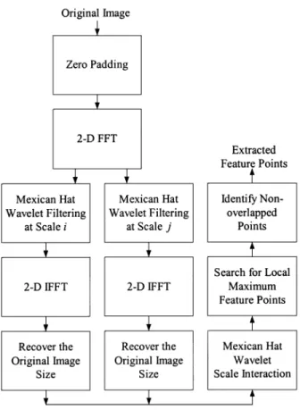
Examples of filtered images at two different scales are shown in Fig. 1(a) and (b). The difference of these two filtered images is the Mexican Hat scale interaction image (with ), which is shown in Fig. 1(c). The two scales we choose are suggested by [1] and [12], that is, and . Feature points are de-fined as local maxima inside disks in the scale interaction image. The disk radius is chosen to be 45, which is determined experi-mentally. Feature points located in regions of small variance are discarded for reducing watermark visibility. A flowchart of the feature extraction method is given in Fig. 2.
Among the many feature extraction algorithms proposed in the literature, we have adopted the scheme proposed in [1] and [12] for several reasons. First, since the Mexican Hat wavelet scale interaction is formed by two scales, it allows different degrees of robustness (against distortion) by choosing proper scale parameters. Second, since local variations such as crop-ping or warcrop-ping generally affect only a few feature points in an image, the unaffected feature points can still be used as refer-ences during the detection process. Third, this wavelet function is rotationally invariant. It means that most feature points may not change after image rotation. Fourth, since the Mexican Hat wavelet is essentially bandlimited, the noise sensitivity problem in feature extraction can be reduced. Finally, the extracted fea-ture points do not shift their locations much under high-quality JPEG compression, as discussed in [1].
These feature points are the centers of the disks that are to be used for watermark embedding (as described in the next sec-tion). Examples of disks are shown in Fig. 1(d). Since these disks should not interfere with each other, we only select the feature points that are away from each other to create a nonover-lapped disk set. In our scheme, a feature point has a higher
pri-Fig. 2. Feature extraction by Mexican Hat wavelet scale interaction
ority for watermark embedding if it has more neighboring fea-ture points inside its disk.
III. IMAGENORMALIZATION
The image normalization technique developed for pattern recognition can be used for digital watermarking, as suggested in [8]. Several geometric central moments are computed to transform the input image to its normalized form. The nor-malized image (object) of a rotated image (object) is the same as the normalized image of the original image (if no padding or cropping occurs). Since objects are rotationally invariant in the normalized image, the watermark detection process can be much simplified when it is applied to the normalized image. On the other hand, because image normalization is sensitive to local image variations, detection is more accurate when applied to individual objects rather than the entire image. In our scheme, we apply the image normalization process to each nonoverlapped local disk separately. The centers of these disks are the extracted feature points described in Section II.
Image normalization technique is used for selecting the loca-tion of the watermarks. However, watermarks are not embedded in the normalized images. This is because spatial interpolation is necessary for mapping the original image pixels to the nor-malized image pixels and vice-versa. This interpolation process induces a significant amount of distortions and thus reduces wa-termark detectability. The details of the image normalization process can be found in [9]. Here, we only briefly describe its computational steps. The parameters below are computed once for each image disk.
1) mean vector , where
where denotes the gray-level value at location , and is the region of interest;
2) covariance matrix , where
;
3) central moments of the original disk; 4) eigenvalues and their associated eigenvectors
of ;
5) two affine transformation coefficient matrices
where ;
6) central moments for calculating rotational invariant trans-formation
7) tensors: , ;
angle:
8) tensor ;
9) If then .
Finally, the normalized image is computed from the original image based on the following coordinate transformation:
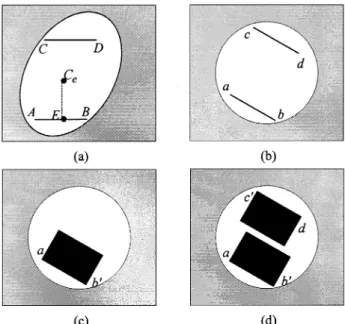
Fig. 3. (a) Two ordered pointsA and B in the normalized image (ellipse). (b) Two corresponding pointsa and b in the original image (disk). (c) A 32 2 32 block is constructed in the original image disk. (d) Two symmetric 322 32 blocks in the original image disk are formed.
where is the original disk coordinates, and is the normalized disk coordinates. The normalized image object is insensitive to translation, scaling, and rotation of the original image object [9].
After coordinate transformation, each disk becomes an el-lipse. Rectangular windows used to hold watermarks in the orig-inal image disks are constructed as follows. Two 32 32 blocks in each (original) image disk are chosen for watermark embed-ding. The locations of these 32 32 blocks are determined through the use of the normalized image ellipse. Since the eigen-values and of the covariance matrix are generally not the same, the shape of the normalized disk is an ellipse. Two ordered points and are chosen at integer coordinates inside the normalized image (ellipse), as shown in Fig. 3(a). The loca-tions of these two points are chosen secretly but are known to the watermark detector. The locations of and are chosen close to the boundary of the normalized ellipse, and the dis-tance between these two points is 32. Points and located in the original image are the inverse mapping of and (on the normalized image), as shown in Fig. 3(b). Usually, points of the inverse mapping of and do not have integer coordi-nates, and thus, points and are quantized to integers. They are connected to form a line segment . Although the distance between points and is 32, the distance between and is generally different due to the normalization process. Therefore, is shortened or extended to the line segment , which has length 32. Usually, point is not the same as point , but these two points are close. Then, 31 line segments parallel to are created running toward the center of the disk. Finally, and its 31 parallel line segments of length 32 form a 32 32 block in the original image, as shown in Fig. 3(c).
Since the 32 points that a line segment passes through do not always have integer coordinates, we choose 32 integer-co-ordinate pels nearest the line segment to form the discrete-grid
Fig. 4. Crossing points of the grid represent the integer pel locations on the original disk. (a) If the slope (absolute value) of a line segment is less than or equal to 1, the integer pels closest to the line segment horizontally are chosen to form the data line segment. (b) If the slope (absolute value) of a line segment is greater than 1, the integer pels closest to the line segment vertically are chosen to form the data line segment.
Fig. 5. Each disk contains two 322 32 blocks for watermark embedding (Lena).
line segment, as shown in Fig. 4(a) and (b). The crossing points of grid represent integer-coordinate pels in the original image (disk). If the absolute value of the slope of a line segment is less than 1, its discrete-grid approximation is constructed along the horizontal direction, as shown in Fig. 4(a). Otherwise, the ver-tical direction is used as shown in Fig. 4(b).
Two 32 32 blocks are selected for each disk, as shown in Fig. 3(d). To reduce the impact of feature point shift due to wa-termark embedding, these blocks should not contain the disk center (feature point). All the location information of these two blocks is determined on the normalized image (ellipse). After the coordinates of and are determined as described above, the coordinates of and will be the symmetric pels with re-spect to the symmetric center [Fig. 3(a)]. is not necessary the center of the ellipse. Point is the middle point of and
. is perpendicular to . The distance between points and is less than 45 but greater than 32. The distance between
and has to be greater than 32. Next, the corresponding pels and in the original image disk are computed by the inverse normalization transformation. A shortened or extended line seg-ment of is , which contains 32 pels. The blocks selected for the image Lena are shown in Fig. 5. Occasionally, a tiny corner (very few pels) of a 32 32 block may be outside the orig-inal image disk. If this happens, these pels are not watermarked. Another potential problem is that although the extracted feature points (center of the disk) are located in high-contrast regions,
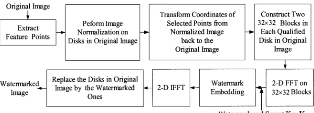
Fig. 6. Watermark embedding scheme.
the two 32 32 selected blocks may be partly located in smooth regions. Therefore, to keep watermark imperceptibility, such a disk is not watermarked if the variance of one 32 32 block in an original image disk is small. In our experiment, there are only eight qualified disks (Fig. 5) for watermark embedding, although there are 11 feature points (disk centers) that are ex-tracted on the Lena image [Fig. 1(d)].
IV. WATERMARKEMBEDDINGSCHEME
Our watermark is designed for copyright protection. We view all blocks as independent communication channels. To improve the robustness of transmitted information (watermark bits), all channels carry the same copy of the chosen watermark. The transmitted information passing through each channel may be disturbed by different types of transmission noise due to inten-tional and uninteninten-tional attacks. During the detection process, we claim the existence of watermark if at least two copies of the embedded watermark are correctly detected.
The watermark embedding process is outlined in Fig. 6. First, the feature extraction method generates reference centers of disks for watermark embedding and detection. We then perform the image normalization technique on disks in the original image. The coordinate transformation coefficients between the original image disks and the normalized ellipse images are generated. The location of blocks in the original image for watermark embedding is determined from the normalized image. Then, coordinates of selected points are transformed from normalized image back to the original image. As a result, the watermark synchronization problem during the detection process is reduced. Next, a 2-D FFT is applied to these 32 32 blocks on each qualified disk in an original image. The watermark is embedded in the transform domain. Last, the watermarked blocks are 2-D IFFT converted back to the spatial domain to replace the original image blocks.
The procedure of selecting and modifying the magnitude of DFT coefficients for watermark embedding is illustrated below. First, the FFT is applied to each 32 32 selected block. Then, several middle DFT coefficients are selected according to the se-cret key . Middle-frequency components are generally more robust in resisting compression attacks. A modified version of [4] is used to embed watermark bits into DFT coefficients.
Se-Fig. 7. Two points(x ; y ) and (0y ; x ), 90 apart on the upper half DFT plane are used for embedding one watermark bit.
lected pairs that are and , apart, located on the upper half DFT plane (see Fig. 7), are modified to satisfy
if if
where and are the magnitudes of the
altered coefficients at locations and in the DFT transform domain, is the watermark strength, and is the binary watermark bit, which is either 0 or 1. The phase of the selected DFT coefficients is not modified. If the watermark bit is 1 and the original amplitude difference between points and is greater than , no change is needed. In addition, to produce a real-valued image after DFT spectrum modification, the symmetric points on the lower half DFT plane have to be altered to the exact same values as well. A larger value of and a longer watermark sequence length would increase the robustness of the watermarking scheme. Because the 32 32 blocks are selected in the high-variance image regions, typically, the embedded watermark is less visible for smaller . Hence, there is a tradeoff between robustness and transparency. In our case, we embed 16 bits in each 32 32 block.
The secret key shown in Fig. 6 is also known to the water-mark detector. This secret key is used as the seed for generating random numbers to specify the frequencies of the DFT coeffi-cients used to hide watermark bits.
V. WATERMARKDETECTIONSCHEME
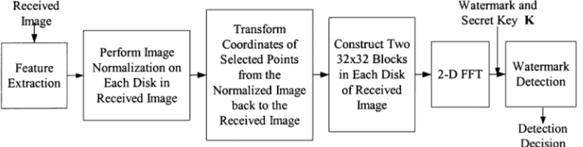
The block diagram of our watermark detection scheme is shown in Fig. 8. The watermark detector does not need the
orig-Fig. 8. Watermark detection scheme.
inal image. The feature (reference) points are first extracted. The feature extraction process is similar to that used in the water-mark embedding process. All the extracted feature points are candidate locations of embedded bits. Since image contents are altered slightly by the embedded marks and perhaps by attacks as well, the locations of extracted feature points may be shifted. In addition, some of the original feature points may fail to show up during the detection process. If the feature point shift is small, the embedded watermark blocks can still be extracted correctly. Image normalization is applied to all the disks centered at the extracted candidate reference points. Two 32 32 blocks are ex-tracted in each disk. The locations of these 32 32 blocks are the same as those specified at watermark embedding. The co-ordinate transformation coefficients between the original image disk and the normalized ellipse image are generated. Thus, the location of blocks in the received image is determined from the normalized image, and the coordinates of the selected points are transformed from normalized image back to the received image. In each 32 32 DFT block, 16 watermark bits are extracted from the DFT components specified by the secret key. For an ex-tracted pair of DFT coefficients and , the em-bedded watermark bit is determined by the following formula:
if if
where and are the magnitudes of the
selected coefficients at locations and . The extracted 16-bit watermark sequence is then compared with the original embedded watermark to decide a success detect.
Two kinds of errors are possible in the detector: the
false-alarm probability (no watermark embedded but detected
having one) and the miss probability (watermark embedded but detected having none). There is a tradeoff between these two error probabilities in selecting detector parameters. Typically, reducing one will increase the other. It is rather difficult to have exact probabilistic models of these two kinds of errors. Simplified models are thus assumed in choosing the detector parameters, as shown below.
We first examine the false-alarm probability. For an unwa-termarked image, the extracted bits are assumed to be indepen-dent random variables (Bernoulli trials) with the same “success” probability . It is called a “success” or “match” if the ex-tracted bit matches the embedded watermark bit. We further as-sume that the success probability is . Let and be the numbers of matching bits in the two blocks on the same disk, and let be the length of the watermark sequence. Then,
based on the Bernoulli trials assumption, and are indepen-dent random variables with binomial distribution
and
The mean values of and are both .
A block is claimed watermarked if the number of its matching bits is greater than a threshold. The thresholds for the two blocks on the same disk are denoted by and . Clearly, and should be greater than , which are the mean values of and
. The false-alarm error probability of a disk is, therefore, the cumulative probability of the cases that and . In order to control the level of false-alarm probability by one adjustable parameter, a third threshold is introduced. More precisely, the variable pairs and will satisfy the following two criteria simultaneously: 1) and 2)
. That is
(5)
Furthermore, an image is claimed watermarked if at least disks are detected as “success.” Under this criterion, the false-alarm probability of one image is
(6)
where is the total number of disks in an image.
We can plot against various
values, as shown in Fig. 9 using (6). The other parameters
are chosen based on our experiences: , ,
, , and . The curve in Fig. 9 drops sharply for . It is often desirable to have a very small . However, the selection is application
Fig. 9. False-alarm probability of an unwatermarked image, assumingn = 16, m = 3, and N = 10.
less than 10 . In this case, should be greater than or equal
to 24, and at , is 5 10 .
We next examine the miss probability. In an attacked water-marked image, we again assume that the matching bits are in-dependent Bernoulli random variables with equal success prob-ability . This may not be a very accurate model, but it seems to be sufficient for the purpose of selecting the detector parameters. The success detection probability of bits in a block of watermarked bits is
Similarly, for the second block
The success detection probability of a disk is the cumulative probability of all the cases that , , and
. That is,
(7)
Recall that an image is claimed watermarked if at least disks watermark detected. Under this criterion, the miss probability of an image is
(8)
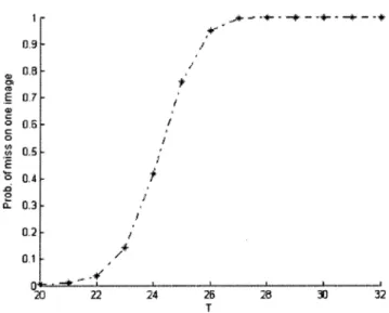
It is difficult to evaluate the success detection probability of a watermarked bit . It depends on the attacks. For ex-ample, the distortion induced by JPEG compression cannot be modeled by a simple additive white Gaussian source. However, a “typical” success detection probability may be estimated from
Fig. 10. Miss probability for the image Lena, assumingn = 16, m = 3, and N = 10.
the experiments on real images with attacks. Because we like to see the detector performance under geometric distortion, a mod-erately difficult case is chosen from Table II—image Lena under combined distortions of 1 rotation, cropping, and JPEG com-pression at a quality factor of 70. The simulation is done using ten watermarked images Lena imposed with (randomly gener-ated) different watermarks. The selected value of is the total number of matching bits divided by the total number of em-bedded bits. In this experiment, we obtain . Based on this value, we plot the miss probability of an image for various , as shown in Fig. 10. In this
experi-ment, we set again , , , ,
and . The curve goes up sharply for . For , is less than 0.42. Clearly, from Figs. 9 and 10, we can see the tradeoff in selecting . Suppose that a lower false-alarm probability is our higher priority in the sim-ulations in Section VI. is therefore chosen to be 24 so that
is less than 10 . VI. SIMULATIONRESULTS
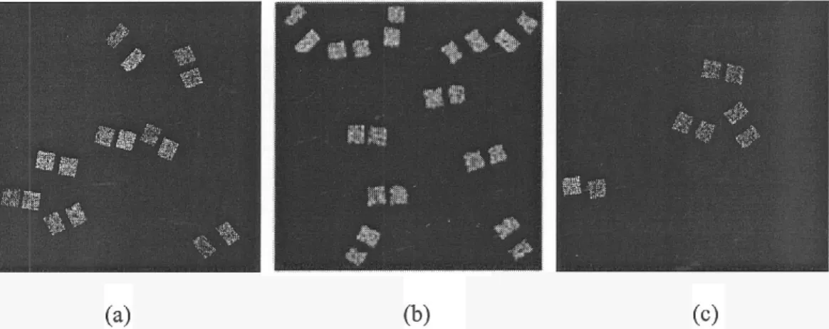
We test the proposed watermarking scheme on the popular test images 512 512 Lena, Baboon, and Peppers. We use StirMark 3.1 [17] to test the robustness of our scheme. The StirMark 3.1 attacks can roughly be classified into two cate-gories: common signal processing and geometric distortions. The difference images between the original images and the wa-termarked images in the spatial domain are magnified by a factor of 30 and shown in Fig. 11(a), (b), and (d). The PSNR values be-tween the original and the watermarked images are 49.42, 45.70, and 56.60 dB for Lena, Baboon, and Peppers, respectively. Be-cause of their small amplitudes, the embedded watermarks are invisible by subjective inspection. Recall that the radius of each disk in the normalized images is 45 and that two 32 32 blocks are chosen in each disk for watermark embedding. In each 32 32 square, the embedded 16 frequencies (of the DFT coeffi-cients) are located within the shaded area of Fig. 12. All blocks are embedded with the same 16-bit watermark. The watermark strength is set to 20, 15, and 10 in Baboon, Lena, and Peppers,
Fig. 11. Difference image between the original image and the watermarked image. The magnitudes in display are amplified by a factor of 30. (a) Lena. (b) Baboon. (c) Peppers.
Fig. 12. Watermarked coefficients are chosen from the shaded area.
respectively, for a compromise between robustness and invisi-bility. Since Baboon image has more texture, a strong water-mark is less visible than in Lena and Peppers. The number of watermarked image disks is 11, 8, and 4 in Baboon, Lena, and Peppers, respectively. The more textured the image is, the more extracted feature points the image has.
Simulation results for geometric distortions and common signal processing attacks are shown in Tables I and II, re-spectively. The tables show the number of correctly detected watermarked disks and the number of original embedded watermarked disks. As shown in Table I, our scheme can resist JPEG compression up to a quality factor of 30. The JPEG compression quantization step size used in StirMark is defined by
Scale qualityquality if quality 50
otherwise.
QuanStepSize BasicQuanMatrix Scale
Our scheme performs well under other common signal pro-cessing attacks such as median filtering, color quantization, 3 3 sharpening, and Gaussian filtering. It can also resist combined signal processing and JPEG compression attacks at a quality factor of 90.
TABLE I
FRACTION OFCORRECTLYDETECTEDWATERMARKDISKSUNDERCOMMON
SIGNALPROCESSINGATTACKS
Some of the signal processing operations used in StirMark 3.1 are detailed below. Color quantization is similar to that in GIF compression. The 3 3 Gaussian filter matrix is
The 3 3 spatial sharpening filter matrix is
The watermark robustness against common signal processing is much improved with stronger watermark strength, but there is the tradeoff between watermark robustness and invisibility.
An additive noise attack was also applied to the watermarked image. The attacked image is
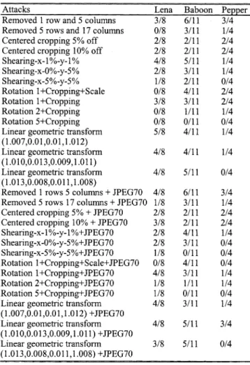
TABLE II
FRACTION OFCORRECTLYDETECTEDWATERMARKDISKSUNDER
GEOMETRICDISTORTIONATTACKS
where is the luminance pixel value of an input image at , is a parameter that controls the strength of the additive noise, is noise with uniform distribution, zero mean, and unit variance, and is the luminance pixel value of the attacked image at . In our experiment, the additive noise is visible, especially in the images Lena and Peppers, when is greater than 0.1. The watermark can be detected when is less than 0.2. As stated in Section II, the noise sensitivity problem in feature extraction is reduced due to the essentially bandlimited property of Mexican Hat scale interaction scheme with proper parameter settings.
The PSNR value (comparison between the watermarked image and the attacked images) in Table III is computed by
PSNR
where is the image size, is the index of each pixel, and and are the gray levels of the original and the processed pixels.
The performance of the proposed scheme under geometric distortions is shown in Table II. Our scheme survives row and column removal, 10% centered cropping, and up to 5% shearing
TABLE III
(NOISE= DIFFERENCEBETWEEN THEWATERMARKEDIMAGE AND THEATTACKEDIMAGES)
Fig. 13. (a) Local warping is applied to watermarked image Lena in the eyes and mouth area. (b) Watermark detection result for (a). Seven watermarked disks are correctly detected among the original eight.
in or direction. Combination of small rotations with crop-ping does not cause our scheme to fail, but it is still sensitive to global image aspect ratio changes due to the feature location shifts. It can also survive combined geometric and high-quality JPEG compression attacks, as shown in Table II. In fact, the correctness of watermark detection under geometric distortions strongly depends on the disk locations. For example, if the refer-ence point of an image disk is located at the border of an image, this point might be removed due to cropping attacks. As a result, this disk location cannot be correctly identified. Rotation with cropping can have to a similar effect.
The Baboon image has deeper and larger textured areas than Lena and Peppers. In the case of Baboon, many fake ence points (feature points) may show up, and the true refer-ence points may shift quite significantly after attacks. On the other hand, Peppers has less texture. Its true feature points may disappear following attacks.
In addition to the geometric distortions in StirMark 3.1, we have applied local warping on the eyes and mouth of Lena, as shown in Fig. 13(a). The extracted disks at detector are shown in Fig. 13(b). Since local variations generally affect only a few feature points extracted by the Mexican Hat wavelet scale inter-action scheme, the feature points can still be correctly extracted for watermark detection. The watermark can still be detected quite reliably.
VII. CONCLUSIONS
In this paper, a digital image watermarking scheme was designed to survive both geometric distortion and signal processing attacks. There are three key elements in our scheme:
1) reliable image feature points; 2) image normalization; 3) DFT domain bits embedding.
No reference images are needed at the detector. A geometric synchronization problem between the watermark embedding and detection is overcome by using visually significant points as reference points. In addition, the invariance properties of the image normalization technique can greatly reduce the watermark search space. The simulation results show that the proposed watermarking scheme performs well under mild geometric distortion and common signal processing attacks. Furthermore, the embedded watermark can resist composite attacks of high-quality JPEG compression together with geometric distortions/signal processing.
The performance of our scheme could be further improved if the feature points were even more robust. Thus, one direc-tion of future research can be the search for more stable feature points and/or more reliable extraction algorithms under severe geometric distortions.
REFERENCES
[1] S. Bhattacharjee and M. Kutter, “Compression tolerant image authen-tication,” in Proc. IEEE Int. Conf. Image Process., vol. 1, 1998, pp. 435–439.
[2] C. Y. Lin, M. Wu, J. A. Bloom, I. J. Cox, M. L. Miller, and Y. M. Lui, “Rotation, scale and translation resilient public watermarking for im-ages,” Proc. SPIE Security Watermarking Multimedia Contents II, vol. 3971, pp. 90–98, 2000.
[3] S. Pereira, J. J. K. ÓRuanaidh, and F. Deguillaume, “Template based re-covery of Fourier-based watermarks using log-polar and log-log maps,” in Proc. IEEE Int. Conf. Multimedia Comput. Syst., vol. 1, 1999, pp. 870–874.
[4] S. Pereira and T. Pun, “Robust template matching for affine resis-tant image watermarks,” IEEE Trans. Image Processing, vol. 9, pp. 1123–1129, June 2000.
[5] ÓRuanaidh and T. Pun, “Rotation, scale and translation invariant digital image watermarking,” in Proc. IEEE Int. Conf. Image Process., vol. 1, 1997, pp. 536–539.
[6] Z. Ni, E. Sung, and Y. Q. Shi, “Enhancing robustness of digital water-marking against geometric attack based on fractal transform,” in Proc.
IEEE Int. Conf. Multimedia Expo., vol. 2, 2000, pp. 1033–1036.
[7] M. Gruber and K. Y. Hsu, “Moment-based image normalization with high noise-tolerance,” IEEE Trans. Pattern Anal. Machine Intell., vol. 19, pp. 136–139, Feb. 1997.
[8] M. Alghoniemy and A. H. Tewfik, “Geometric distortion correction through image normalization,” in Proc. IEEE Int. Conf. Multimedia
Expo., vol. 3, 2000, pp. 1291–1294.
[9] S. C. Pei and C. N. Lin, “Image normalization for pattern recognition,”
Image Vision Comput., vol. 13, no. 10, pp. 711–723, Dec. 1995.
[10] M. Alghoniemy and A. H. Tewfik, “Image watermarking by moment invariants,” in Proc. IEEE Int. Conf. Image Process., vol. 2, Jan. 2001, pp. 73–76.
[11] A. Nikolaidis and I. Pitas, “Robust watermarking of facial images based on salient geometric pattern matching,” IEEE Trans. Multimedia, vol. 2, pp. 172–184, Sept. 2000.
[12] M. Kutter, S. K. Bhattacharjee, and T. Ebrahimi, “Toward second gener-ation watermarking schemes,” in Proc. IEEE Int. Conf. Image Process., vol. 1, 1999, pp. 320–323.
[13] P. Bas, J.-M. Chassery, and B. Macq, “Robust watermarking based on the warping of pre-defined triangular patterns,” Proc. SPIE Security and
Watermarking of Multimedia Contents II, vol. 3971, pp. 99–109, 2000.
[14] J.-P. Antoine and P. Vandergheynst, “Two-dimensional directional wavelets in image processing,” Int. J. Imag. Syst. Technol., vol. 7, pp. 152–165, 1996.
[15] D. Marr, Vision. San Francisco, CA: Freeman, 1982, pp. 54–61. [16] B. S. Manjunath, C. Shekhar, and R. Chellappa, “A new approach to
image feature detection with applications,” Pattern Recogn., vol. 29, no. 4, pp. 627–640, 1996.
[17] Stirmark. [Online]. Available: http://www.cl.cam.ac.uk/~fapp2/water-marking/stirmark/
Chih-Wei Tang received the B.S. and M.S. degrees
in computer science and information engineering from National Chiao-Tung University, Hsinchu, Taiwan, R.O.C., in 1995 and 1997, respectively. She is currently pursuing the Ph.D. degree with the Department of Electronics Engineering, National Chiao-Tung University.
From 1997 to 1998, she was a senior engineer with ZyXEL Corporation, Hsinchu. From 1998 to 1999, she served as an assistant editor for the
Taiwanese Journal of Mathematics. Her research
interests include multimedia digital watermarking/data hiding and multimedia digital signal processing.
Hsueh-Ming Hang (F’02) received B.S. and M.S.
degrees from National Chiao Tung University, Hsinchu, Taiwan, R.O.C., and the Ph.D. degree in electrical engineering from Rensselaer Polytechnic Institute, Troy, NY, in 1984.
From 1984 to 1991, he was with AT&T Bell Laboratories, Holmdel, NJ. He joined the Elec-tronics Engineering Department of National Chiao Tung University, Hsinchu, in December 1991 and currently is a Professor. He holds seven US patents and one R.O.C. (and Japanese) patent and has published over 100 technical papers related to image compression, signal processing, and video codec architecture. He was an area editor of the Journal
of Visual Communication and Image Representation (Academic Press) from
1996 to 1998. He is a co-editor of and contributor to the Handbook of Visual
Communications (New York: Academic, 1995).
Dr. Hang has been a chair or co-chair for many international conferences. He was an associate editor of IEEE TRANSACTIONS ONIMAGEPROCESSINGfrom 1992 to 1994 and the IEEE TRANSACTIONS ONCIRCUITS ANDSYSTEMS FOR
VIDEOTECHNOLOGYfrom 1997 to 1999. He received IEEE Third Millennium Medal and is a member of Sigma Xi.