Vision-Based Vehicle Surveillance and Parking Management
Using Multiple Cameras
Li-Chih Chen
1, Jun-Wei Hsieh
2, Wei-Ru Lai
1, Chih-Xuan Wu
1, and Shin-Yu Chen
1 1Department of Electrical Engineering 2Department of Computer Science and Engineering Yuan-Ze University National Taiwan Ocean University 135 Yuan-Tung Road, Chung-Li 320, Taiwan 2 Pei-Ning Road, Keelung ,Taiwan
Abstract
This paper proposes a vision-based vehicle surveillance system for parking management in outdoor environments. Due to the limited field of view of camera, this system uses multiple cameras for monitoring a wide-area parking lot. Then, an affine transformation is used for linking the relations between cameras. Two major components are included in this system, i.e., vehicle counting and parking place management. For the first one, this system integrates three features, i.e., color, position, and motion together for well tracking vehicles across different cameras. Thus, even though two vehicles are occlude together, they still can be well identified and tracked under different lighting changes. For the second one, we propose a grid-based approach to model the color change of floor for determining whether a parking space is vacant. Due to the perspective effects, the visibility of a parking space is often affected by the vehicle parking on its neighbor space. To tackle this problem, we divide a parking space to different grids with different weights. Then, according to the orientation of parking space. an automatic weighting scheme is proposed for measuring the visibility of each grid. By judging the quantity of edge, we can determine whether the parking spaces are vacant. The experimental results reveal that our system works well and accurately in several different conditions.
Keyword: surveillance system, affine transform,
vehicle surveillance, parking management, background subtraction
1. Introduction
Nowadays, video surveillance becomes more and more popular in many applications. Considering the surveillance system used in a wide range, such as campus, airport and shopping mall, it needs many cameras to build a video-sensor network due to the limited field of camera. Thus, it has to use many cameras to observe the trajectories and the behaviors
of objects for a good surveillance system. In [8], Hsieh proposed a fast stitching algorithm to stitch images. There are many different applications, such as video compression, video indexing, object tracking, or creation of virtual environments.
There are a lot of approaches which had been proposed to object tracking and object detection. In [26], Song et al. used vehicle shape models, camera calibration and ground plane knowledge to detect and track moving vehicles. In [30], Wang discriminated moving cast shadows and handled non-stationary background processes for real-time vehicle detection. In [21], Lou et al. provided an efficient pose refinement method to refine the vehicle’s pose parameters. They also used an improved EKF to track and predict vehicle motion with a precise kinematics model. Leibe et al. [19] proposed a system to integrate information over long time periods. Besides, they revised the decision and recovered from mistakes in the light of new evidence without using Markov assumption. In [13], Kasturi et al. proposed a framework for evaluating the performance of object detection and tracking algorithms. The source video data, ground-truth annotations, performance metrics, evaluation protocols, tools including scoring software and baseline algorithm are included in this framework. In [17], Kluckner et al. used an on-line boosting algorithm to incrementally improve the detection results. In [4], Eshel et al. tracked the detected head tops via common assumptions on motion direction and velocity. Zhu et al. [35] presented a sequential architecture for efficient car detection under complex outdoor scene. In [23], they proposed a method to track non-rigid objects by using a covariance based object description and Lie algebra based update mechanism. In [12], they proposed a multilevel homography to track and detect object from a low-angle off-axis camera. Ablavsky et al. [1] used a layered image-plane representation for tacking people through substantial occlusions. In [25], Seemann et al. presented a generative object model that is capable to scale from a general object class model to a more specific object. Bernardin et al. [2] proposed a combination of Haar-feature classifier-based detection and color histogram filtering used to achieve reliable initialization of person tracks even in the presence of camera
movement.
In addition to the above approach, there are still many papers discussing occluded object tracking. Lin et al. [20] described a Bayesian approach to human detection and segmentation combining local part-based and global template-based schemes. Ryoo et al. [24] presented an approach called “Observe and Explain” which can solve track humans and objects under severe occlusion. In [32], their numerical hybrid local and global mode-seeking trackers are available on challenging airborne videos with heavy occlusion and large camera motions. Zhang et al. [34] proposed a network flow based optimization method for data association needed for multiple object tracking. Yu et al. [33] looked upon the multi-target tracking as a missing data problem, and the solution is found by the variational EM algorithm. Ess et al. [5] presented a mobile vision system for multi-person tracking in busy environments. In order to track pedestrians which have occlusion frequently, their system integrates continuous visual odometry computation with tracking-by-detection.
In the parking lot, in addition to the sensor, the camera is also a mechanism to detect whether a parking space is vacant or not. Wu et al. [31] used an 8-calss Support Vector Machine (SVM) classifier to distinguish each parking space. Huang et al. [9] proposed a 3-layer Bayesian hierarchal detection framework (BHDF) for robust parking space detection. They used local classification model, global semantic model and adjacency model. They also used the vehicle color and edge map [29] to model vehicles.
In this thesis, we propose a framework to accomplish parking management. First, we build an environment by stitching four images which have some overlapped regions among the images. Then, we can use background subtraction to extract foreground objects that can be tracked individually. The system combines appearance and temporal information in order to track objects. In the appearance part, the system records the information which includes color and edge of vehicle in each parking space. In the temporal part, the results of object tracking make sure whether the parking space is occupied or not.
This thesis is organized as followings. Section 2 introduces the overview of our proposed system. Section 3 describes the details of camera synchronization. Section 4 explains the main methods of object tracking. Section 5 presents the parking space detection. The experimental results are presented in Section 6. Conclusions and further research directions are presented in Section 7.
2. System Overview
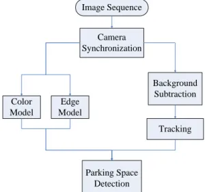
The flowchart of the proposed method is shown in Fig. 1. Image Sequence Camera Synchronization Parking Space Detection Tracking Color Model Background Subtraction Edge Model
Fig. 1 Flowchart of proposed system
First, the image sequences are captured from four cameras, and these four cameras’ scenes have some partial overlapped regions. We can take advantage of affine transform [8] to merge them. We use the method of background subtraction to extract foreground information. There are many approaches on background subtraction. We evaluate several methods for extracting well foreground regions and find that some methods have well performance under different environments with some special conditions.
Finally, we choose “Codebook” model [15] as our background subtraction model in our system. Via the background subtraction model, our system can extract well foreground regions but it still has some noise or error sometimes. To reduce these noises, this system proposes to use morphology and connected component algorithm [28].
In tracking, each foreground object has been labeled an ID after using connected component algorithm. Each same object has the same label ID between frames. Hence, we can compute all of the foreground objects between frames. Because the object does not disappear suddenly, we can find the same object by calculating the distance. The “Existent Value” is defined how many frames the object exists. If the existent value of an object is higher than a threshold, the object would be tracked.
The location of each parking space is marked manually in advance because the cameras are static. We do the edge detection for each parking space. If a parking space is vacant, the quantities of edge pixels would be less or empty. On the other hand, if a parking space is occupied, the quantities of edge pixels would be more. Because the size of each parking space is different, the edge rate is used to
detect whether a parking space is vacant. Moreover, the color feature is focus on floor color that is another key issue in our study. If a parking space is vacant, its color almost is the floor color. If a parking space is occupied, its color almost is various.
3. Camera Synchronization
The cameras’ synchronization will be described in this section. There are four cameras in this system. Because the images of four cameras have some partial overlapped regions, these images of the cameras can be merged to a big image.3.1 Time Alignment
In this system, we use four cameras to capture the different scene’s images from different cameras. Because the frame rate is not equal between each camera, the difference is also not the same between frames. The difference is not equal between each cameras and frames. To solve this problem, the minimum value has to be computed firstly. When the system runs, the difference to the minimum value is below 200 milliseconds will be update on each camera. It means it is not probably to update four images every execution time, hence sometimes it updates one camera or four cameras in order to make sure the images are captured from different cameras synchronously.
3.2 Affine Transform
In our study, we use affine transform to stitch different images form different cameras so as to form a wide range image for observed clearly. The transformations of an image are usually classified into three parts, and there are rotation, scaling and translation. According to the affine transform, the two images that exists the overlap region can be merged.
In Fig. 2 and Fig. 3, we show the experimental results of merging images.
(a) (b)
(c)
Fig. 2 The merge result of the images of camera 1 and camera 2. (a) The image from the camera 1. (b) The image from the camera 2. (c) The merge result of (a) and (b)
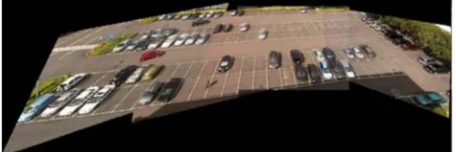
Fig. 3 The merge result of four cameras
4. Object Tracking Method
In this section, it will describe full tracking procedures in our system. The pre-processes separated into two parts: “Background Subtraction” and “Remove Foreground Noise”. In background subtraction, the background modeling method was based on codebook scheme [14][15] as the main method. In the part of removing foreground noises, the main purpose is to fix errors which are occurred from background subtraction. The method which the system uses in this part must be simple and does not cost too many system resources for applying in real-time system. In tracking, it can be separated into two parts. There are “Non-occlusion Tracking” and “Occlusion Tracking” in this thesis.4.1 Background Subtraction
There are many background subtraction approaches have been discussed. Gaussian Mixture Model (GMM) is a basic model for modeling background information in many surveillance applications. Davis et al. [3] [7] proposed a non-parametric background model for background subtraction. The model could adaptively learn information of scene for modeling background effectively and could model shadows for the purpose of shadow removing. Javed et al. [11] proposed an edge based model for background subtraction. They used the gradient information for advanced verifying foreground regions which were caused by the condition of lighting effect.
In this system, the operator uses the foreground model which was proposed by Kim et al. [14] [15]. Kim proposed a background modeling algorithm which is called “Codebook”. He modeled background information with multiple color and brightness models. Different from Gaussian Mixture Model, size of model from different pixel is not the same. The size of model at each pixel is dynamic by the variation of pixel in the training procedure. Background model could learn to overcome the change of scene in the procedure of detection and apply in real-time system. Pixel which is considered as foreground pixel is decided by the distance between input data and codebook models in background database. For example, in Fig. 4, Vt
means the vector of the information of single pixel and Vb means one of codebook models in database.
The similarity from the part of color is the distance c which is the length of vector Vt projected orthogonal
to vector Vb. The similarity from the part of
brightness is the distance between vectors Vt
projected on vector Vb and vector Vb. The decision of
foreground pixel is based on a combination between the similarity from parts of color and brightness from all codebook models in the pixel.
Fig. 4 Color model for background subtraction.
4.2 Remove Foreground Noise
To remove noises of foreground information which is caused by background subtraction, this system proposes to use morphology and connected component to overcome it. After morphology process, connected components algorithm [28] is used to label foreground regions into an index table for each view.
4.3 Non-Occlusion Tracking Analysis
In this Section, we will introduce the tracking method foreground objects which do not have occlusion. After processing connected component method, every foreground objects can obtain its numbers. In image sequence, if each foreground object does not have occlusion, the number of eachforeground object should be maintained the same in this situation. In this thesis, the distance of all foreground objects between frames is used to determine whether these objects are the same one. In Fig. 5, the same object has the minimum distance to itself in the next frame can be known. For this reason, we can record the center of all foreground objects frame by frame to compute the distance.
(a)
(b)
Fig. 5 The foreground on adjacent frames. (a) The foreground in frame 77 (b) The foreground in frame 78
{
}
( ') arg min ( , ) t j i j P I same i dis O P ∈ =,
(1)where Pj is a foreground object in the current frame
and dis O P( i, j) the Euclidean distance between Oi and P . j
4.4 Occlusion Tracking Analysis
When some foreground objects have occurred the occlusion situation. First, the distance between the foreground objects must be calculated in Fig. 6.
center1
center2 center1
center2
Fig. 6 Distance before occlusion.
Let 1 O C and 2 O
C denote the centers of two
objects O1 and O2 , respectively. In addition,
width1, height1, width2 and height2 are the width and
height of object1 and object2 respectively. Before the foreground objects have occlusion, these objects can be found by Eq. (3) and Eq. (4).
1 1 1 2 1 1 . . 2 2 x O O dif = C x−C x− w − w , (3)
and
1 1 1 2 1 1 . . 2 2 y O O dif = C y−C y− h − h . (4) When diffx and dify are both smaller than a threshold, it is looked upon as having occlusion. When two objects have occlusion, they can not be found a unique corresponding object in next frame. After these objects are found, some of information of them can be recording in advance. After the occlusion is over, these objects which are separated from occlusion will be compared with the objects which are recording before. The information includes of color, motion and size. The K-L distance method is used to compare the color information.
The K-L distance [18] is used to model cost(Q,D) as Eq.(5). The K-L distance is the non-commutative measure of the difference between two probability distributions PQ and PD. It measures
the expected difference in the number of bits required to code samples from when using codes based on PQ
and PD. Typically, PQ represents the “true”
distribution of data, observations, or a precise calculated theoretical distribution. The measure PQ
typically represents a theory, model, description, or approximation of PD. In the system case, PQ and PD
are both the color histograms for observation.
4095 0 [ ] cos ( , ) [ ]* log [ ] Q Q i D P i t i j P i P i = ⎡ ⎤ = − ⎢ ⎥ ⎣ ⎦
∑
.
(5)The motion information is mainly focus on its displacement of x-coordinate and y-coordinate. The movement of all the object has inertial. So, the motion value of the object from occur occlusion multiplied by the motion value of the object after occur occlusion is positive. There are pedestrians, motorcycles and vehicles in the parking lot. The sizes of the foreground objects are different. In general, the size of pedestrian is smaller than the size of vehicles in the same camera. For this reason, the size is a feature that can be used to track object, too.
On the other hand, when the two objects started to be overlapped, the Particle Filter [22] can be used to find out the possible positions of these two objects respectively.
The idea of the particle filter is to introduce the recursive Bayesian filter base on sample sets was independently proposed by several groups [6][10][16]. The mainly idea of particle filter is modified from the Condensation algorithm. The particle filter algorithm is very similar to the mean-shift one but the difference is that the particle filter combines with Monte Carlo rule and condensation algorithm to filter out the new object position frame by frame. The experimental results present Fig. 7.
(a) (b) (c)
(d) (e) (f)
(g) (h) (i)
Fig. 7 Tracking results using particle filters. (a) Initial kernel. (b) Generate the random around the initial kernel. (c) State transition. (d) Four good samples are reserved. (e) New samples will occur. (f) Prediction. (g) and (h): Measurements. (i) Tracking result.
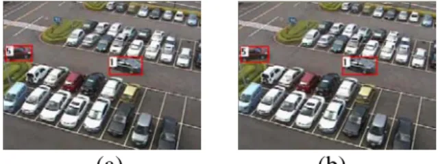
The relation between each camera and the merged picture can be obtained. According to the merged picture, we can know which point corresponds to the same position between cameras. Therefore, if the foregrounds correspond to the same position between cameras, it could make sure that the foregrounds are the same object. For this reason, the object track across cameras can be solved. When an object will move across cameras, it has shown in another camera in Fig. 8.
Fig. 8 The same object correspond to the same position
5. Parking Space Detection
The parking space detection is another aim of our effort. Because the data of this thesis is in the same scene, each location of the parking spaces can be gotten manually at first, show in Fig. 9. Each parking space in the camera has different size, so some parking spaces can be marked because its size is smaller or not obvious. Because the locations are
gotten first, the center of each parking space is easily obtained. (a) (b) (c) (d)
Fig. 9 Mark each parking space manually. (a) Marked parking space on camera 1. (b) Marked parking space on camera 2. (c) Marked parking space on camera 3. (d) Marked parking space on camera 4.
5.1 Edge-based Detection
(a) (b)
(c) (d)
Fig. 10: Ellipse Marks in each parking space from four cameras. (a) Camera 1. (b) Camera 2. (c) Camera 3. (d) Camera 4.
When the cameras are static, the locations of the parking spaces can be calculated at first. A car has many edges and the vacant parking space has less edge even no edge in the parking space. We should detect it based on the rate of the edge of each parking space. Each parking space has four white lines in its boundary, so it is not good to count the edge in the whole parking space range. If the edges are computed in the entire parking space range, it would get some non-useful edges. Therefore, the method proposed to calculate the edges of parking space is count the edges by using ellipse shape in each parking space, it shows in Fig. 10.
Instead of using circle shape in each parking space, using ellipse shape is more practical. Almost most of parking spaces are ellipse shape. If using circle shape in every parking space, it would lose some information.
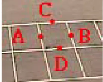
Fig. 11 The four points of the center of four boundaries on each parking space.
About the size of ellipse, each parking space certainly has different sizes. Because the locations of each parking space have known before, the four points of four corners of each parking space also can be obtained. After the four points are obtained, the center point of four sides can be calculated. Connect to center points of the symmetrical two sides in Fig. 11, and the half of longer line is the major axis of ellipse, the half of shorter one is the minor axis of ellipse for each parking space. They are defined as follows: min( , ) Minor= AB CD , and max( , ) Major= AB CD ,
where Minor and Major are double of the minor axis and double of the major axis, respectively, A and B are the center points of symmetrical two sides; C and D are the center points of the other symmetrical sides. Therefore, the straight ellipse can be drawing in the center of each parking space. Then, the angle between the major axis of ellipse and horizontal line will be calculated in Eq. (8) as follows:
2 1 2 1 tan(y y ) arc x x θ = − −
, (8)
where the x2 and y2 are the coordinate of one end
of the longer line and the x1 and y1 are the
coordinate of the other end of longer line. The ellipse should be rotated according to the following equation: 2 1 2 1 cos sin sin cos x x y y θ θ θ θ − ⎡ ⎤ ⎡ ⎤⎡ ⎤ = ⎢ ⎥ ⎢ ⎥⎢ ⎥ ⎣ ⎦ ⎣ ⎦ ⎣ ⎦
,
(9)where θ is the angle between the major axis of ellipse and horizontal line.
In order to analyze vehicle, the feature “edge map” is also used in this thesis for vehicle representation. The difference of Gaussian (DOG) filter is used for extracting edge points at this stage. The scale space of an image is defined as a function,
( , , )
L x yσ , which is produced from the convolution
of a variable-scale Gaussian, G x y( , , )σ with an input image I x y( , ) by the formula:
( , , ) ( , , ) ( , )
L x yσ =G x yσ ∗I x y , (10) where
∗
is the convolution operation in x and y, and2 2 2 2 1 ( , , ) exp 2 2 x y G x yσ σ πσ ⎡ + ⎤ = ⎢− ⎥ ⎣ ⎦. (11)
The edge point can be extracted efficiently with D x y( , , )σ , which is computed from the difference of two nearby scales separated by a constant multiplicative factor k:
( , , ) ( ( , , ) ( , , )) ( , ) ( , , ) ( , , ). D x y G x y k G x y I x y L x y k L x y σ σ σ σ σ = − ∗ = − (12)
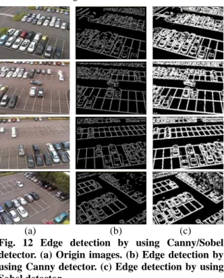
Based on Eq.(12), similar to Canny edge detector [27], different edge points can be then detected. In addition to Canny edge detector, another edge detector, Sobel edge detector, can be considered.
(a) (b) (c)
Fig. 12 Edge detection by using Canny/Sobel detector. (a) Origin images. (b) Edge detection by using Canny detector. (c) Edge detection by using Sobel detector.
In Fig. 12, the difference between these methods can be known. Base on Eq. (13), when the quantity is smaller than a threshold,
( )
edge number of edge ellipse
T size of parking space
∩ <
, (13) it means the parking space is vacant.
5.2 Color-based Model
Due to the static cameras, the special position can be recorded in advance. In order to detect whether a parking space is vacant, the floor color is
an important feature. The floor region in the parking lot can be also marked manually, as shown in Fig. 13. First, calculate the mean and the variance of color in the regions. Then, compare with each parking space and floor color in each parking space. Because the region of floor color will vary with time, the mean and the variance of color in the floor region should update with time, too. Especially, not only the shadow but also the sunlight will vary with time.
(a) (b)
(c) (d)
Fig. 13 Mark floor regions in four cameras. (a) Mark floor region on camera 1. (b) Mark floor region on camera 2. (c) Mark floor region on camera 3. (d) Mark floor region on camera 4.
(a) (b)
Fig. 14 The parking space occludes adjacent one. (a) Occlude right (b) Occlude left.
In addition, each parking space has some occlusion due to the occupied parking space around. Similar to Section 5.1, the method is not focus on all parking spaces. According to Eq. (8), the angle of each parking space can be obtained. The angle which is from 0 degree to 90 degree and from 180 degree to 270 degree of the parking space will occlude to the left parking space in Fig. 14(b); the angle which is from 90 degree to 180 degree and from 270 degree to 360 degree of the parking space will occlude to the right parking space in Fig. 14(a).
In real cases, due to the viewing angle, a parking slot will contains other colors due to vehicle occlusion. Like Fig. 15, the parking slot (denoted by a red rectangle) is occupied by other vehicle colors due to occlusions. To more accurately determine whether a slot is really available, we divide it into four grids (see Fig. 15). Different grids own different weights to determine the probability that a
parking slot is available. Thus, according to different viewing angle, different weight is assigned to each grid. Let R denote the parking slot, githe
ith grid in R, wgi the weight of gi. Then, the score to determine whether R is an available parking space is defined as ( ) i i i g g g R Score R c w ∈ =
∑
,
(14) where i gc is the ratio of pixels in gi belonging to the floor color. Base on Eq. (14), when the probability is greater than a threshold, it means the parking space is vacant.
(a) (b)
Fig. 15 Parking slot separated into four grids. (a) Occlusion at the right side. (b) Occlusion at the left side.
In above features, the operator should find an equation to combine the two features. Even if the smaller parking space has some edge points, it still has higher rate. In this case, the color feature is more stable. If the ratio of height to width is greater than a threshold, the parking space is defined small. We detect the smaller parking space using more color feature; on the other hand, we detect the bigger parking space using more edge feature.
6. Experimental Results
The experimental results of our system show in Fig.16 and Fig.17. In all the experiments, the image sequences (JPG) are with the dimension 320x240 that images are captured by IP camera. In all our experiments, the upper parts are the input frame from the IP cameras and the lower parts are the result by merging four camera frames.
6.1 Object Tracking
Fig. 16 Object tracking in frame 73.
Fig. 17 Object tracking in frame 169
We evaluated the performance of our algorithm on 8 minutes video. There were 72 moving objects, including cars, pedestrians, and motorcycles; 60 objects were correctly tracked from beginning to end. 8 objects change it ID label in video. And 7 objects missed sometimes.
Table 1 The accuracy rate, false alarm rate and miss rate of object tracking
Accuracy rate 83.333%
False Alarm rate 11.111%
Miss rate 9.722%
6.2 Parking Space Detection
This section illustrates the experimental results of parking space detection. In this part, we use four methods to detect vacant parking space. There are edge-ellipse, edge-four regions, color-ellipse and color-four regions. These results of proposed method will be presented below.
6.2.1 Edge-ellipse method
Fig. 18 Result of parking space detection by using edge-ellipse method.
Table 2 The accuracy rate, false alarm rate and miss rate of the parking space detection by using edge-ellipse method Test video True-Positive 493 False-Positive 38 True –Negative 816 False-Negative 26 Accuracy rate 92.843%
False Alarm rate 4.449%
Miss rate 5.009%
6.2.2 Edge-based method
Fig. 19 The result of parking space detection by using edge-four regions method
Table 3 The accuracy rate, false alarm rate and miss rate of the parking space detection by using edge-four regions method
Test video True-Positive 414 False-Positive 748 True -Negative 97 False-Negative 112 Accuracy rate 35.628%
False Alarm rate 88.520%
Miss rate 21.292%
6.2.3 Color-ellipse method
Fig. 20 The result of parking space detection by using color-ellipse method
Table 4 The accuracy rate, false alarm rate and miss rate of the parking space detection by using color-ellipse method Test video True-Positive 468 False-Positive 26 True -Negative 812 False-Negative 46 Accuracy rate 94.736%
False Alarm rate 3.102%
Miss rate 8.949%
6.2.4 Color-four regions method
Fig. 21 The result of parking space detection by using color-four regions method
Table 5 The accuracy rate, false alarm rate and miss rate of the parking space detection using color-four regions method
Test video True-Positive 473 False-Positive 81 True –Negative 765 False-Negative 44 Accuracy rate 85.379%
False Alarm rate 9.574%
Miss rate 8.510%
6.3.5 Proposed method
Fig. 22 The result of parking space detection by using proposed method
Table 6 The accuracy rate, false alarm rate and miss rate of the parking space detection of proposed method True- positive False- positive True- negative False- negative Accuracy rate False Alarm rate Miss rate Video1 237 4 338 10 98.340% 1.653% 4.049% Video2 288 2 242 6 99.310% 0.819% 2.041% Video3 168 9 364 4 94.915% 2.413% 3.488% Video4 225 5 314 4 97.826% 1.567% 1.747% Video5 174 2 362 4 98.863% 0.549% 2.247% Video6 183 6 205 2 96.825% 2.843% 1.081% Video7 273 10 419 8 96.466% 2.331% 2.847%
Fig. 23 The result of parking space detection by using proposed method
Fig. 24 The result of parking space detection in different scene
Fig. 25 The result of parking space detection in different scene
In above results, the result of edge-four regions method is not acceptable because the edges of vehicles are not always distributed over four regions equally. By using edge-ellipse method, the smaller parking spaces can not detect correctly because the ranges of them are too small to obtain the smaller
ratio of edge to range. So, in order to solve the smaller parking space, we combine the color method to detect them. Sometimes the shadow will occur in some parking spaces so the color method is not always acceptable. For example, a parking space is vacant but it has shadow. In this case, the color model will result in error detection because the shadow color is different from other floor color. So, the edge method is more useful than the color model. The proposed system can work stably in outdoor environment. Fig. 24 and Fig. 25 show the experimental results that reveal our system can work in different lighting situations.
7. Conclusions
In this study, we proposed the method of object tracking and parking space detection between multiple overlapping cameras. The framework which we proposed is smart and adapted for both overlapping and non-overlapping cameras. The parking space detection will not need to train in advance. The algorithm can be executed by using multiple cameras.
Experimental results show that our proposed method in parking space detection is robust and stable in various viewpoints. Besides, our system can track objects across cameras on multi-camera. For parking management, our system can utilize the result of tracking to assist it and not need to train in advance.
In the future, the primary tasks are overcoming the change of illumination change in multi-view, and our algorithm can obtain the location of each parking space automatically. Finally, we hope that our proposed system can be more robust to use for real world application.
8. Reference
[1] V. Ablavsky, A. Thangali, and S. Sclaroff, “Layered graphical models for Tracking Partially-Occluded Objects,” IEEE Computer
Society Conference on Computer Vision and Pattern Recognition, Jun. 2008.
Stiefelhagen, “Automatic Person Detection and Tracking using Fuzzy Controlled Active Cameras,” IEEE Conference on Computer
Vision and Pattern Recognition, Jun. 2007.
[3] A. Elgammal, D. Harwood, and L. Davis, “Non-parametric Model for Background Subtraction,” European Conference on Computer Vision (ECCV), pp.751-767, 2000.
[4] R. Eshel and Y Moses, “Homography Based Multiple Camera Detection and Tracking of People in a Dense Crowd,” IEEE Conference
on Computer Vision and Pattern Recognition,
Jun. 2008.
[5] A. Ess, B Leibe, K. Schindler, and L. V. Gool, “A Mobile Vision System for Robust Multi-Person Tracking,” IEEE Conference on
Computer Vision and Pattern Recognition, Jun.
2008.
[6] N. Gordon, D. Salmond, and C. Ewing, “Bayesian state estimation for tracking and guidance using the bootstrap filter,” Journal of
guidance, control and dynamics, pp. 1434-1443,
1995.
[7] T. Horprasert, D. Harwood, and L. S. Davis, “A Statistical Approach for Real-time Robust Background Subtraction and Shadow Detection,” IEEE International Conference on
Computer Vision (ICCV), pp.1-19, 1999.
[8] Jun-Wei Hsieh, “Fast Stitching Algorithm for Moving Object Detection and Mosaic Construction,” Proceedings of International
Conference on Multimedia and Expo, pp.I-85-8,
Jul. 2003.
[9] C.C. Huang, S. J. Wang, Y. J. Chang, and T. Chen, “A Bayesian Hierarchical Detection Framework for Parking Space Detection,”
IEEE International Conference on Acoustics, Speech and Signal Processing, pp. 2097-2100,
Apr. 2008
[10] M. Isard and A. Blake, “Contour Tracking by Stochastic Propagation of Conditional Density,” European Conference on Computer
Vision, pp. 343-356, 1996.
[11] O. Javed, K. Shafique, and M. Shah, “A Hierarchical Approach to Robust Background Subtraction using Color and Gradient Information,” Proceedings of IEEE Motion and Video Computing, pp.22-27, 2002.
[12] N. K. Kanhere, S. J. Pundlik, and S. T. Birchfield, “Vehicle Segmentation and Tracking from a Low-Angle Off-Axis Camera,” IEEE Computer Society Conference
on Computer Vision and Pattern Recognition,
vol. 2, pp. 1152-1157, Jun. 2005.
[13] R. Kasturi, D. Goldgof, P. Soundararajan, V. Manohar, J. Garofolo, R. Bowers, M. Boonstra, V. Korzhova, and J. Zhang, “Framework for Performance Evaluation of Face, Text, and Vehicle Detection and Tracking in Video: Data, Metrics, and Protocol,” IEEE transactions on
Pattern Analysis and Machine intelligence, vol.
31, no. 2, pp. 319-336, Feb. 2009.
[14] K. Kim, T. H. Chalidabhongse, D. Harwood, and L. Davis, “Background Modeling and Subtraction by Codebook Construction,” IEEE
International Conference on Image Processing (ICIP), vol. 5, pp.3061-3064, 2004.
[15] K. Kim, T. H. Chalidabhongse, D. Harwood, and L. Davis, “Real-time foreground - background segmentation using codebook model,” Real-time Imaging, vol. 11, no. 3, pp.172-185, 2005.
[16] G. Kitafgawa, “Monte Carlo Filter and Smoother for non-Gaussian Nonlinear State Space Models,” Journal of Computation and
Graphical Staticstics, pp. 1-25, 1996.
[17] S. Kluckner, G. Pacher, H. Grabner, H. Bischof, and J. Bauer, “A 3D Teacher for Car Detection in Aerial Images,” International Conference on
Computer Vision, Oct. 2007.
[18] S. Kullback, Information theory and statistics, Dover Books on Mathematics.
[19] A. Leibe, K. Schindler, N. Cornelis, and L. V. Gool, “Coupled Object Detection and Tracking from static cameras and moving vehicles,”
IEEE transactions on Pattern Analysis and Machine intelligence, vol. 30, no. 10,
pp1683-1698, Oct. 2008.
[20] Z. Lin, L. S. Davis, D. Doermann, and D. DeMenthon “Hierarchical Prat-Template Matching for Human Detection and Segmentation,” International Conference on
Computer Vision, Oct. 2007.
[21] J. Lou, T. Tan, W. Hu, H. Yang, and S. J. Maybank, “3-D Model-Based Vehicle Tracking,” IEEE transactions on Image
Processing, vol. 14, no. 10, pp. 1561-1569, Oct.
2005.
[22] K. Nummiaro et al., “A Color-based Particle Filter,” ECCV, pp. 53-60, 2002.
[23] F. Porikli, O. Tuzel, and P. Meer, “Covariance Tracking using Model Update Based on Lie Algebra,” IEEE Computer Society Conference
on Computer Vision and Pattern Recognition,
vol. 1, pp. 728-735, Jun. 2006.
[24] M. S. Ryoo and J. K. Aggarwal, “Observe-and-explain: A new Approach for Multiple Hypotheses Tracking of Humans and Objects,” IEEE Conference on Computer Vision
and Pattern Recognition, Jun. 2008.
[25] E. Seemann, M. Fritz, and B. Schiele, “Towards Robust Pedestrian Detection in Crowded Image Sequences,” IEEE Conference
on Computer Vision and Pattern Recognition,
Jun. 2007.
[26] X. Song and R. Nevatia, “A Model-based Vehicle Segmentation Method for Tracking,”
International Conference on Computer Vision,
vol. 2, pp. 1124-1131, Oct. 2005.
Processing, Analysis and Machine Vision,
London, U. K. Chapman & Hall, 1993.
[28] L. D. Stefano and A. Bugareli, “A Simple And Efficient Connected Components Labeling Algorithm,” Proceedings of International
Conference on Image Analysis and Processing,
pp.322-327, 1999.
[29] L. W. Tsai, J. W. Hsieh, and K. C. Fan, “Vehicle Detection Using Normalized Color and Edge Map,” International Conference on Image
Processing, vol. 2, pp. 598-601, 2005.
[30] Y. Wang, “Real-Time Moving Vehicle Detection With Cast Shadow Removal in Video Based on Conditional Random Field,” IEEE
transactions on Circuits and Systems for Video Technology, vol. 19, no. 3, pp. 437-441, Mar.
2009.
[31] Q. Wu, C. C. Huang, S. Y. Wang, W. C. Chiu, and T. H. Chen, “Robust Parking Space Detection Considering Inter-Space Correlation,” IEEE International Conference
on Multimedia and Expo, pp. 659-662, Jul.
2007.
[32] Z. Z. Yin and R. T. Collins, “Object Tracking and Detection after occlusion via Numerical Hybrid Local and Global Mode-Seeking,”
IEEE Conference on Computer Vision and Pattern Recognition, Jun. 2008.
[33] T. Yu, Y. Wu, N. O. Krahnstoever, and P. H. Tu, “Distributed Data Association and Filtering for Multiple Target Tracking,” IEEE
Conference on Computer Vision and Pattern Recognition, Jun. 2008.
[34] L. Zhang, Y. Li, and R. Nevatia, “Global Data
Association for Multi-Object Tracking Using Network Flows,” IEEE Conference on
Computer Vision and Pattern Recognition, Jun.
2008.
[35] Z. Zhu, Y. Zhao, and H. Lu, “Sequential Architecture for Efficient Car Detection,” IEEE
Conference on Computer Vision and Pattern Recognition, Jun. 2007.